[Eleonora, Matteo]
MODULATION
Excitations are sent in pitch
INPUT MIRROR: 15.5 Hz
END MIRROR: 18.5 Hz
Amplitude: 10000 count
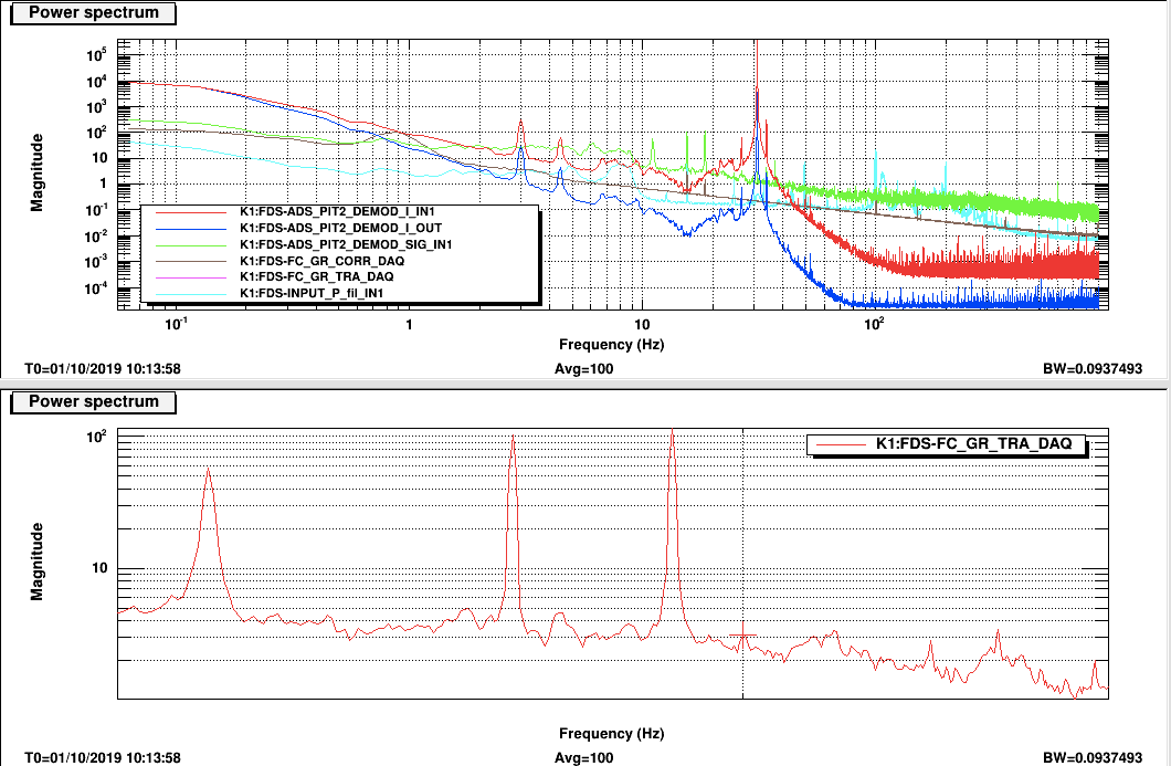
Both lines are well visible in the transmitted power. (Pic1, bottom)
DEMODULATION
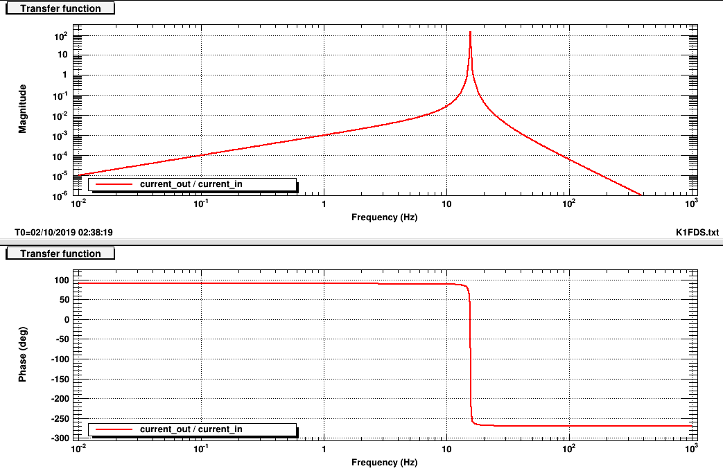
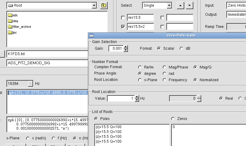
Before the demodulation the transmitted power is filtered with a resonant filter at the modulation frequency (see pic 2-3)
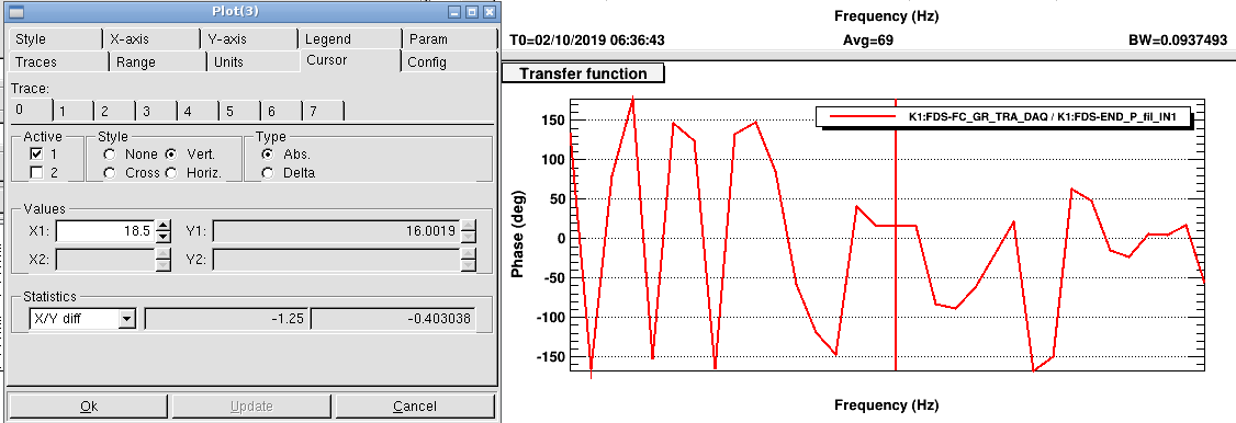
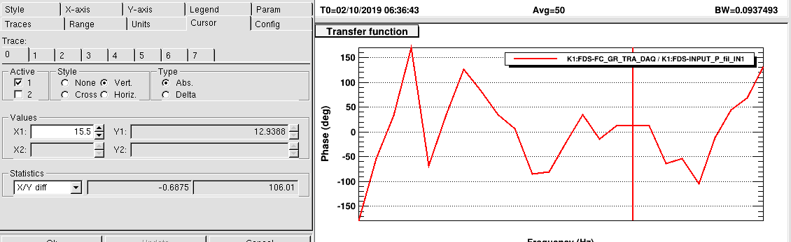
The demodulation phase is chosen by looking at the transfer function between the injected line (seen on the oplev) and the transmitted power. This phase is ~12 deg for both input and end (pic 4-5)
The demodulated signal is filtered with a first order low pass (simple pole) at 0.3 Hz.
The spectra of the demodulated signal after and before lowpass look as expected. (Pic 1 top. Blue and Red)
ERROR SIGNALS
Error signals are very noisy (see some examples in the attached pdf). To investigate their goodness we have misaligned in turn the input and end mirror of a known amount of counts and measured the change in count of the two error signals. The results are not very clear, nevertheless we have tried to compute a sensing matrix.
| demod INPUT | demod ERR | |
| input misaligned | -300 | 1500 |
| end misaligned | -700 | 13000 |
It seems quite unbalanced and not very reasonable. Another suspicious thing is that error signal behavior is not very reproducible.
It seems they are affected by some variables which we are not considering and controlling.