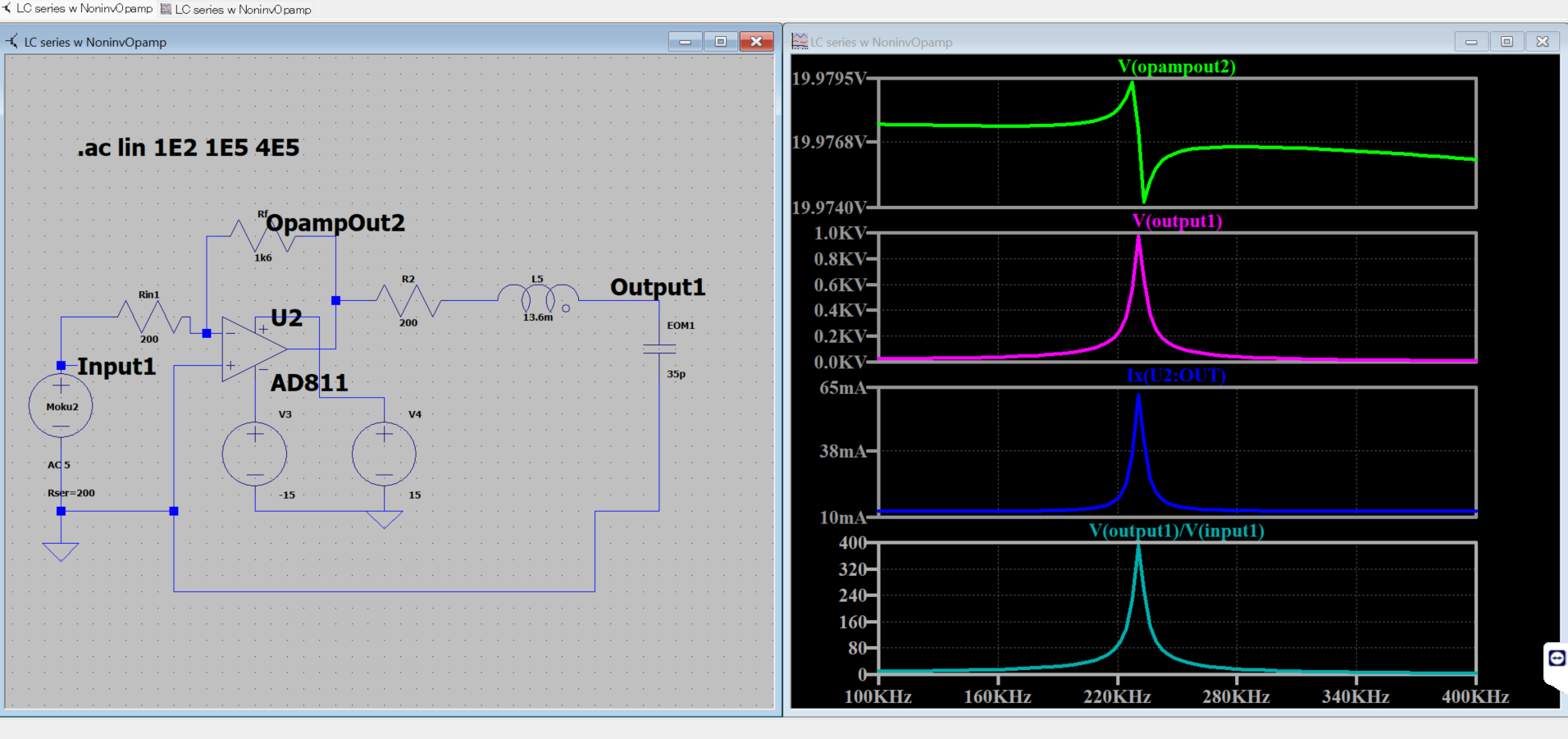
Now, I am using an Opamp EL2099CT, which has output current limit of 440mA. I made a inverting amplifier circuit (Fig 4). The spectrum was first observed with HV probe across the EOM, then by using the PD response with laser input across the EOM. There is impedance matching with moku using Rin=200ohm.
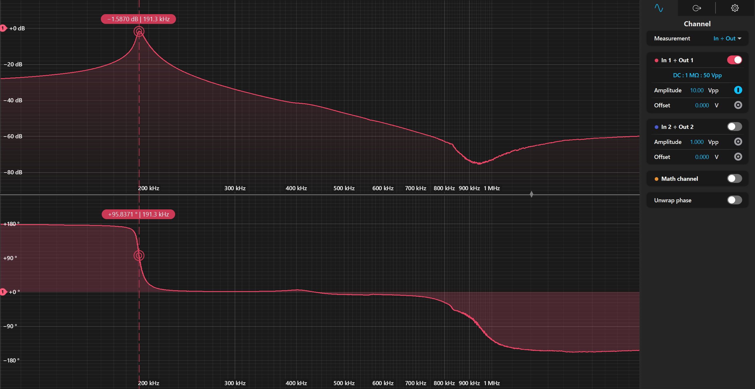
fig 1 : full TF using HV probe - 100:1 (no laser)
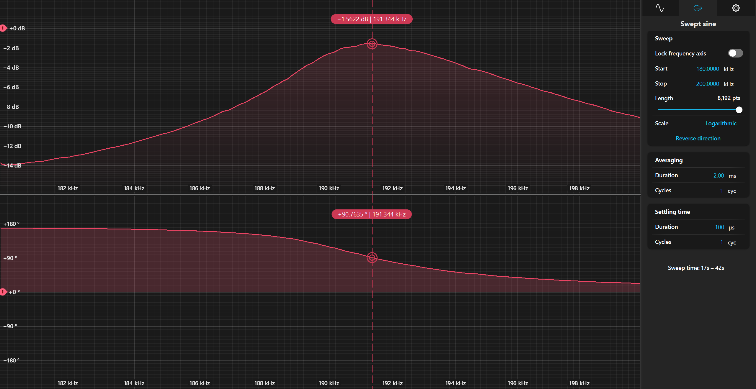
fig 2; zoomed of Fig 1
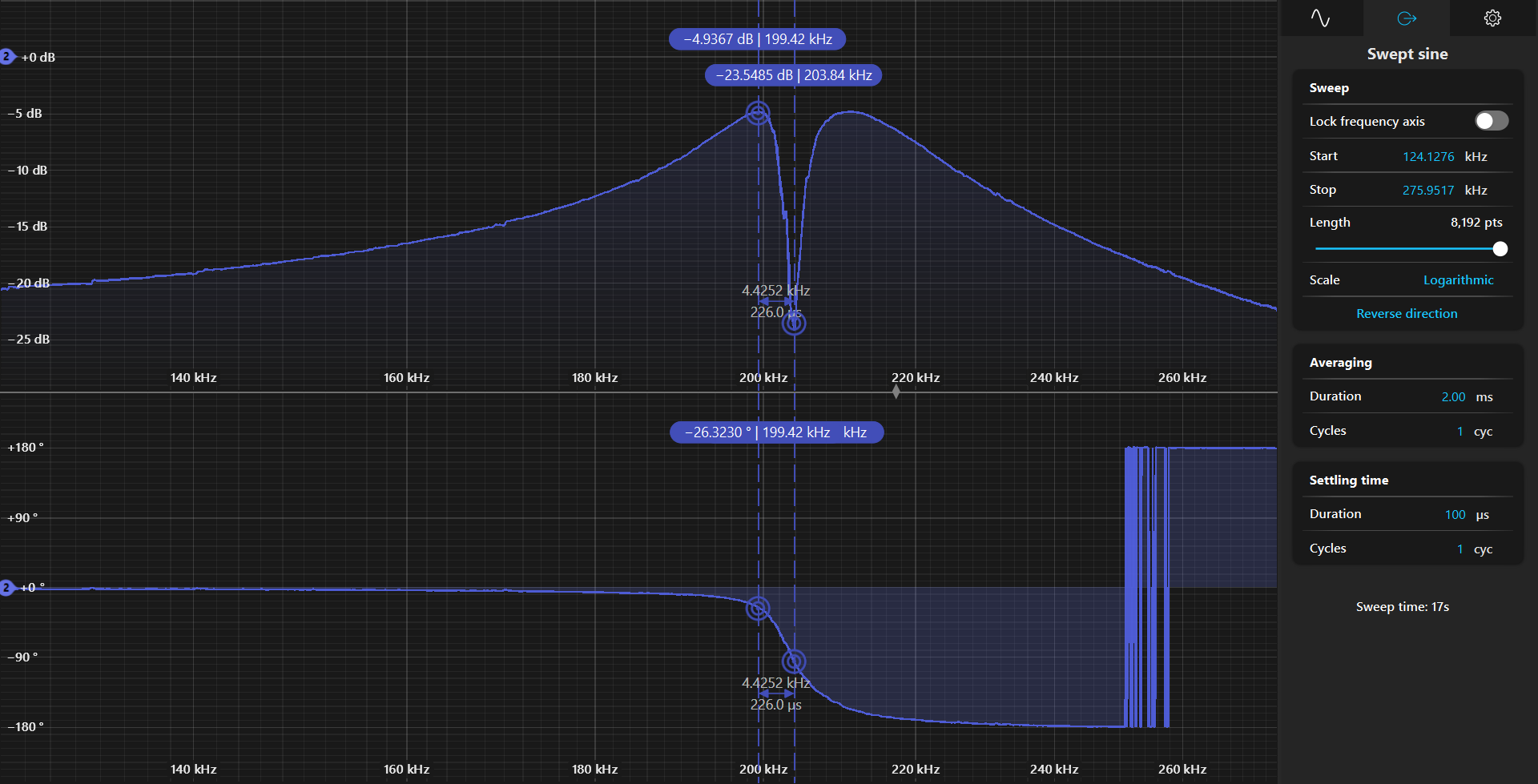
fig 3: TF measurement with laser (no HV probe)
Although the TF seems fine in Fig 1 and 2, there is something different in Fig 3. It could be the response of the PD.
I seem to have a gain of -1.5dB (with 100x probe)
so, 0.89*100 = 89 gain.
With 5V (amplitude), my circuit, should generate 89*5V= 445V , across EOM.
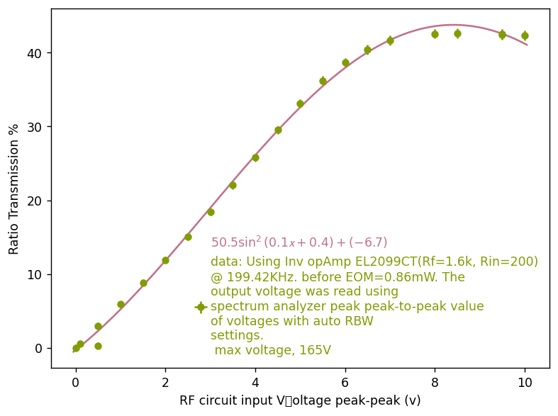
But, the response, seems saturated. See Fig 5. The rms voltage of the photodiode was converted to power.
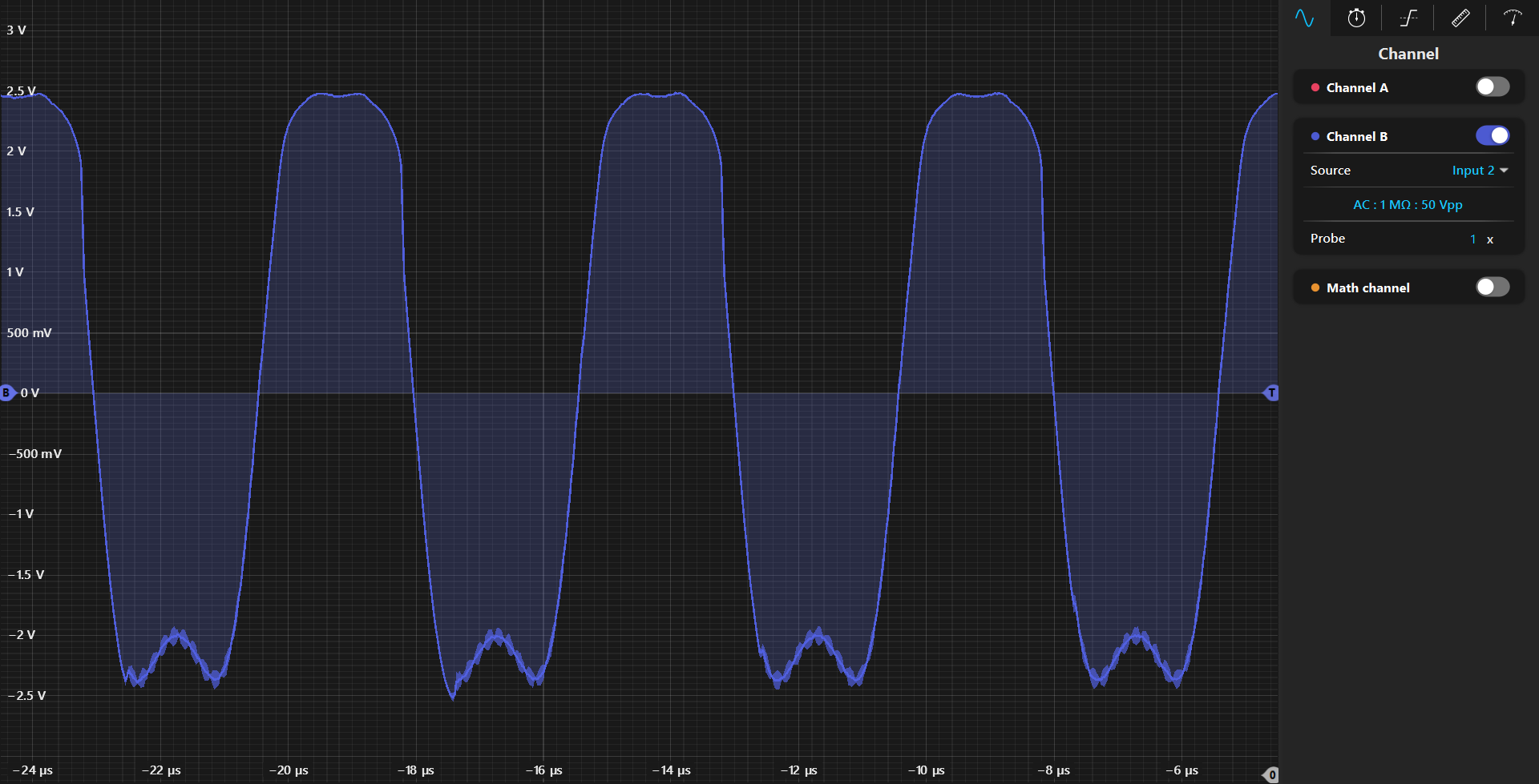
It was quite absurd that I still had saturation. See Fig 6 of photodiode response in oscilloscope.
Then, it occured to me, that the saturation has to do with limit of photodiode response itself. Since I am using a fixed gain photodiode, the maximum voltage it can read is 0-10V (for highZ), which means 10Vp-p. Since Moku input impedance is 1Mohm, it implies that I am limited by the photodiode response.
Next step:
Use a variable gain PD.