The work in this elog was done when I got back from Australia but I forgot to post it.
---
In the last update I fixed the stability of the green injection system. The GRMC error signal demodulation signal from DDS2 DAC2 was found to be drifting in phase with respect to other DDS channels. Switching to the free channel DDS2 DAC0 allowed for the GRMC to stay locked for 1 hr+.
The squeezer has been off since I went to Australia so I turned it back on in the hope that nothing is broken. If everything goes well I hoped to check that we can inject high green power to show that the stable operation really is recovered.
PLLs
I turned on the PLLs and loaded the settings from the PLL software. I did not see any PLL sidebands on the CC spectrum analyzer, and while I could see sidebands on the ppol spectrum analyzer, it would not lock. So I measured the signal levels going into the PLL servo.
CC LO in - 21 MHz 8.22 dBm ok
CC Beat in - ~ -1 dBm ok
ppol LO in - 39 MHz 7.9 dBm ok (39 MHz is the current optimal ppol frequency for maximum nonlinear gain)
ppol Beat in - no signal. I could see a ppol beat signal on the ppol PLL monitor cable though.
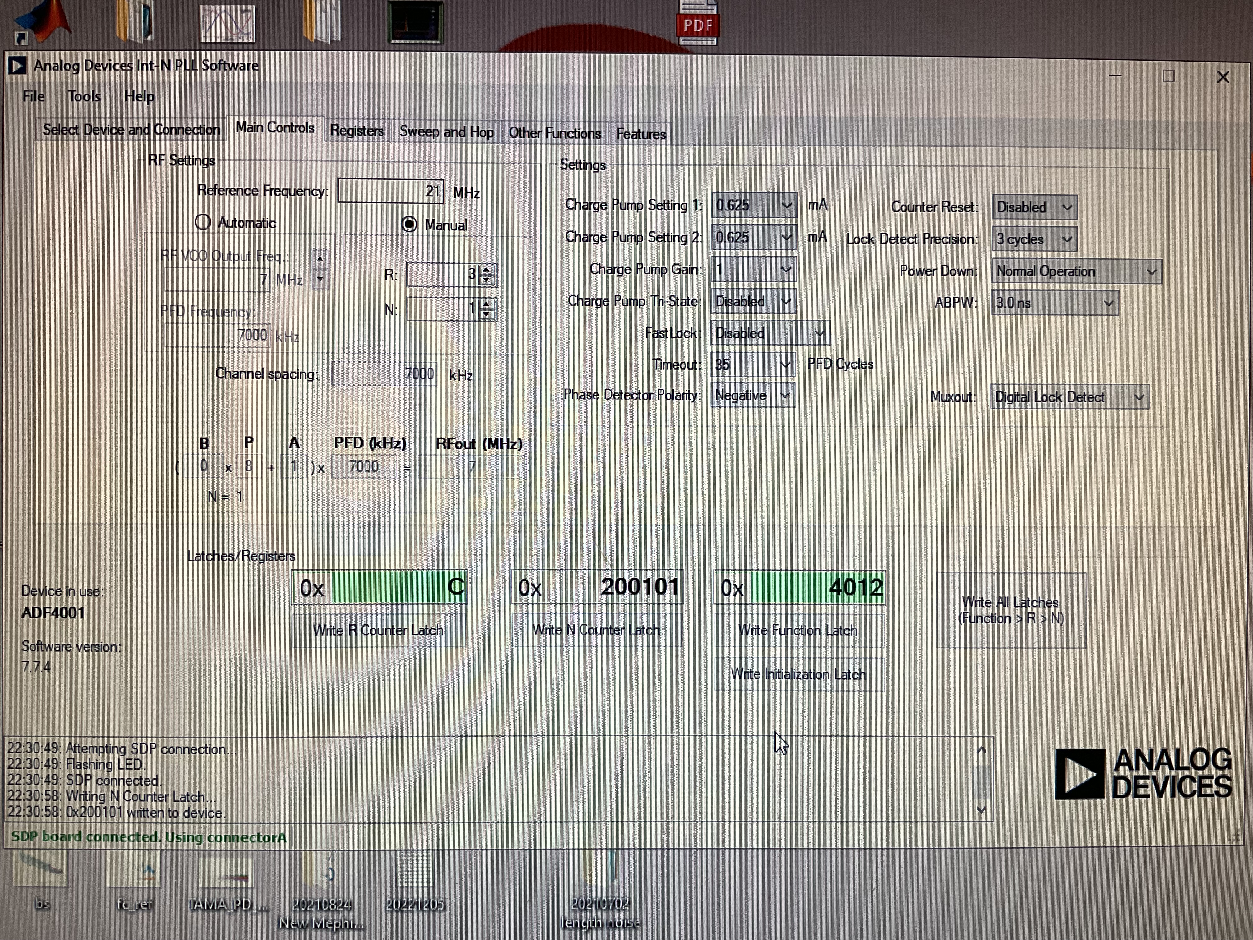
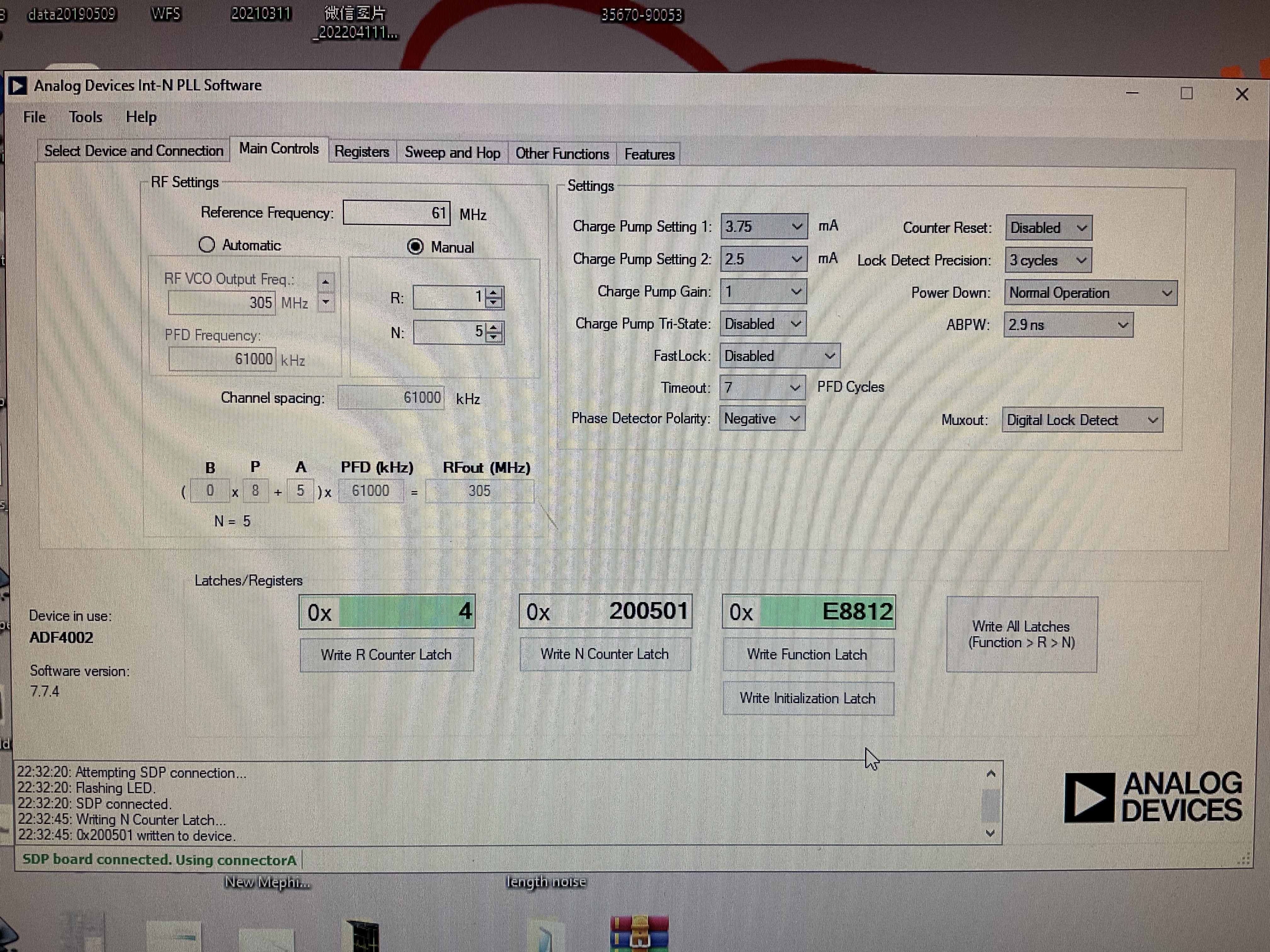
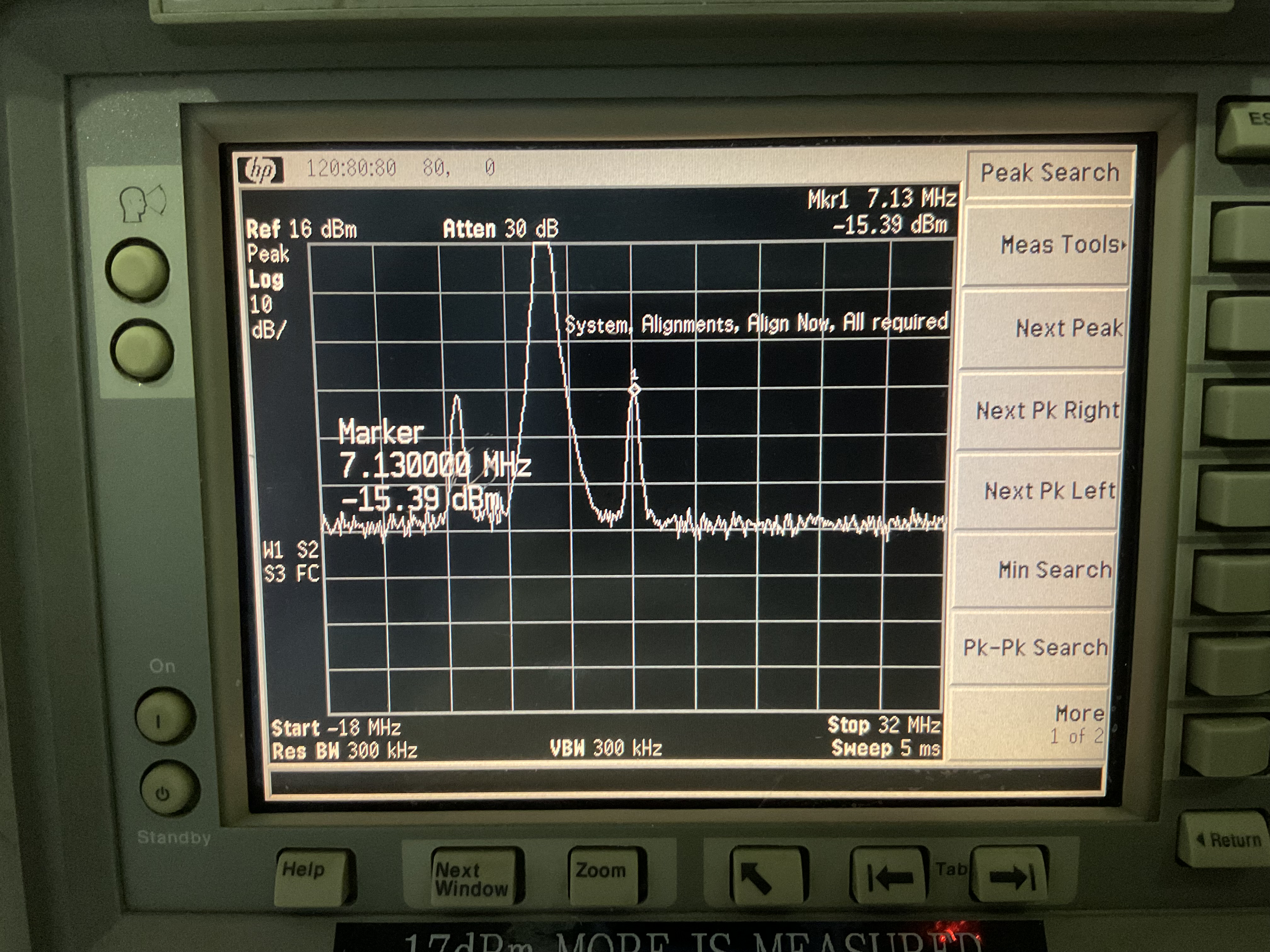
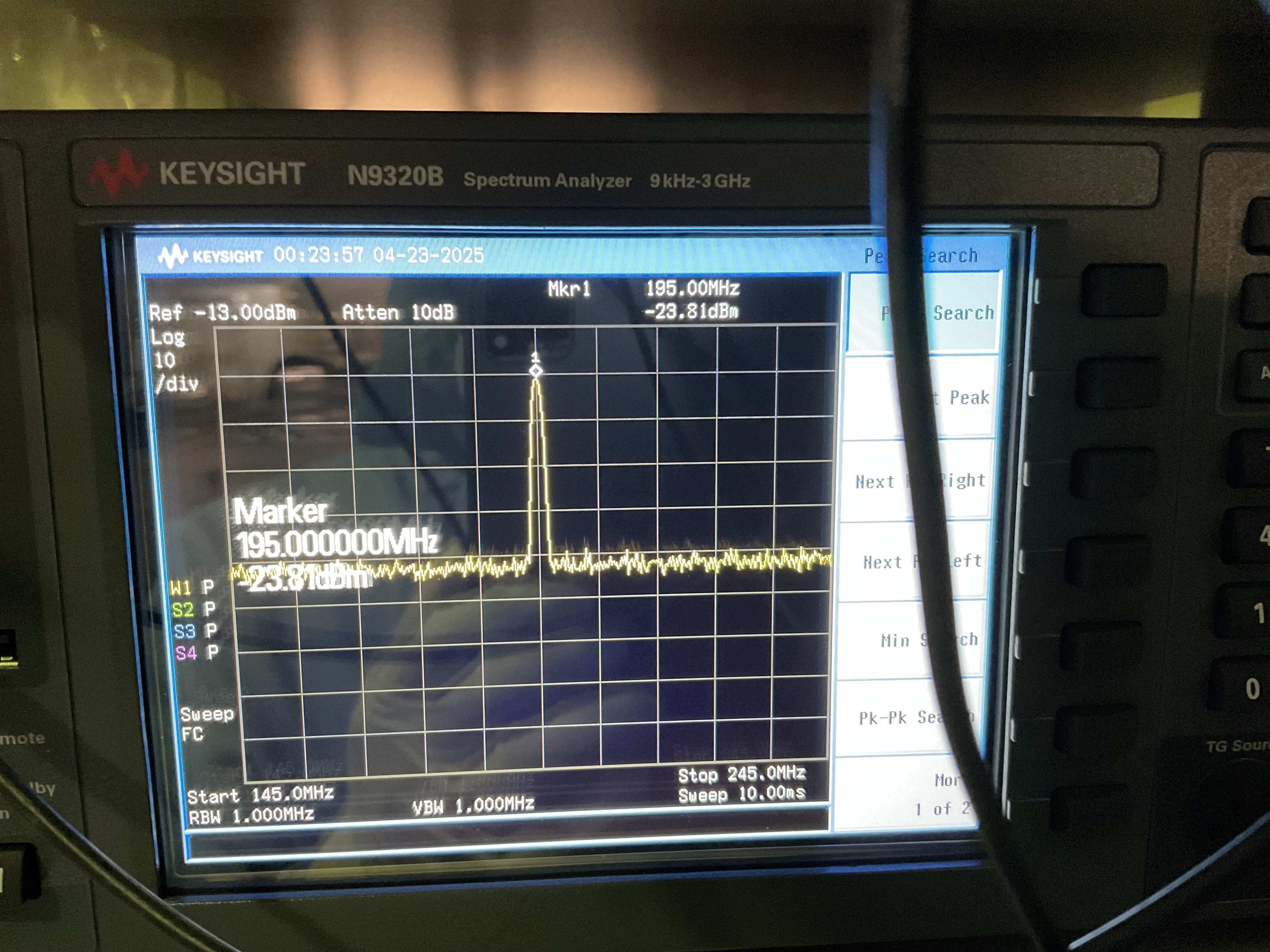
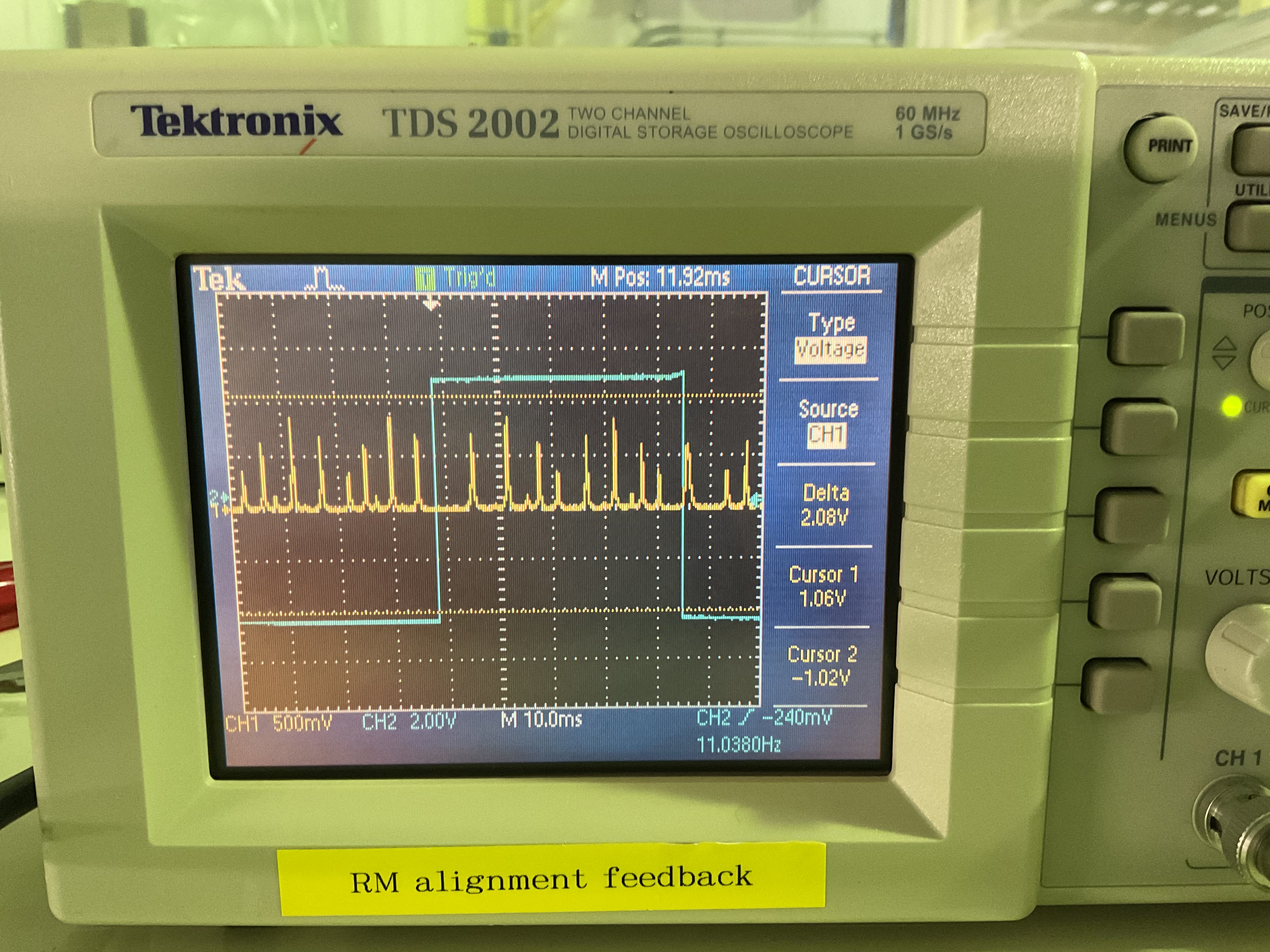
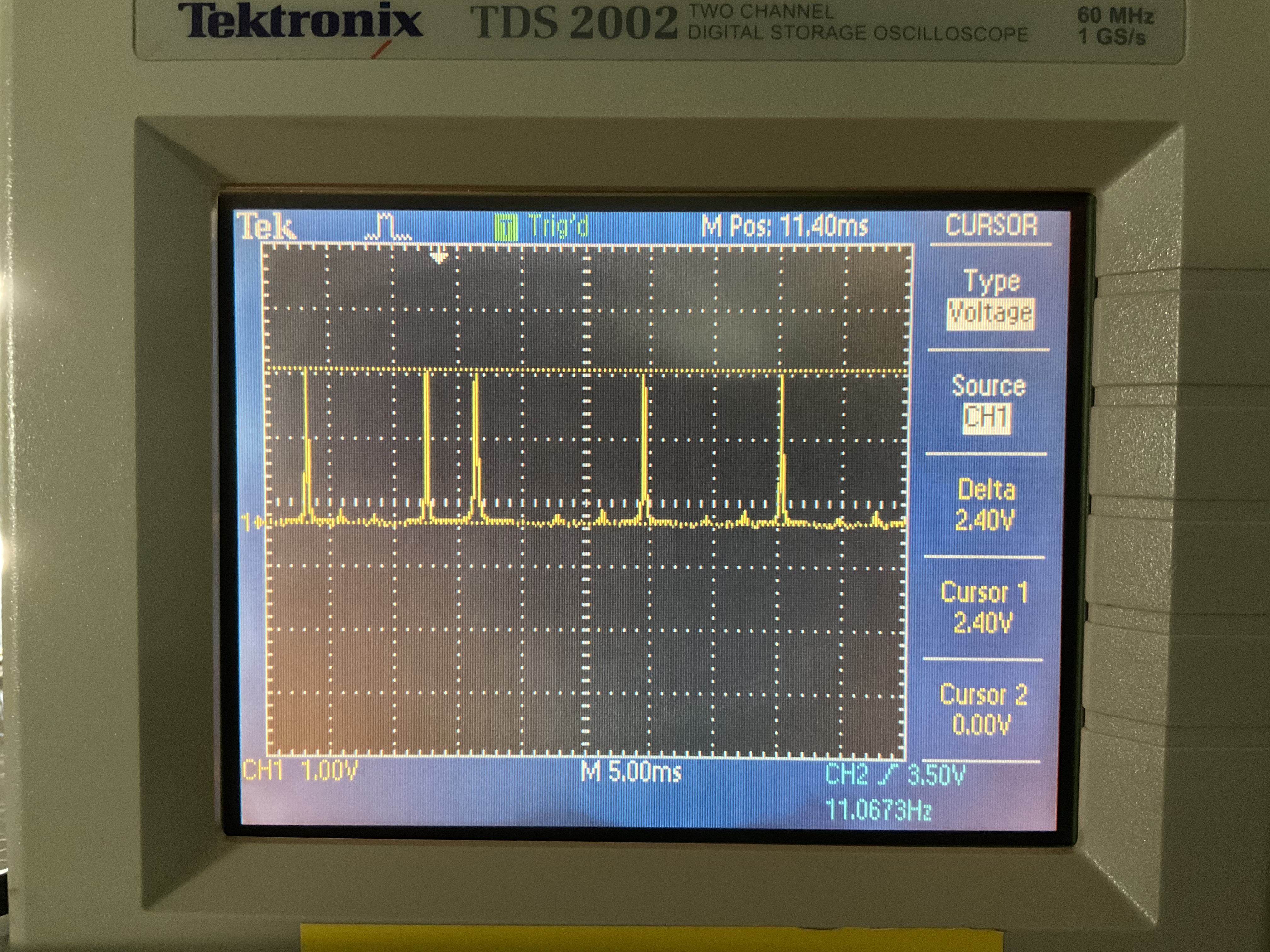
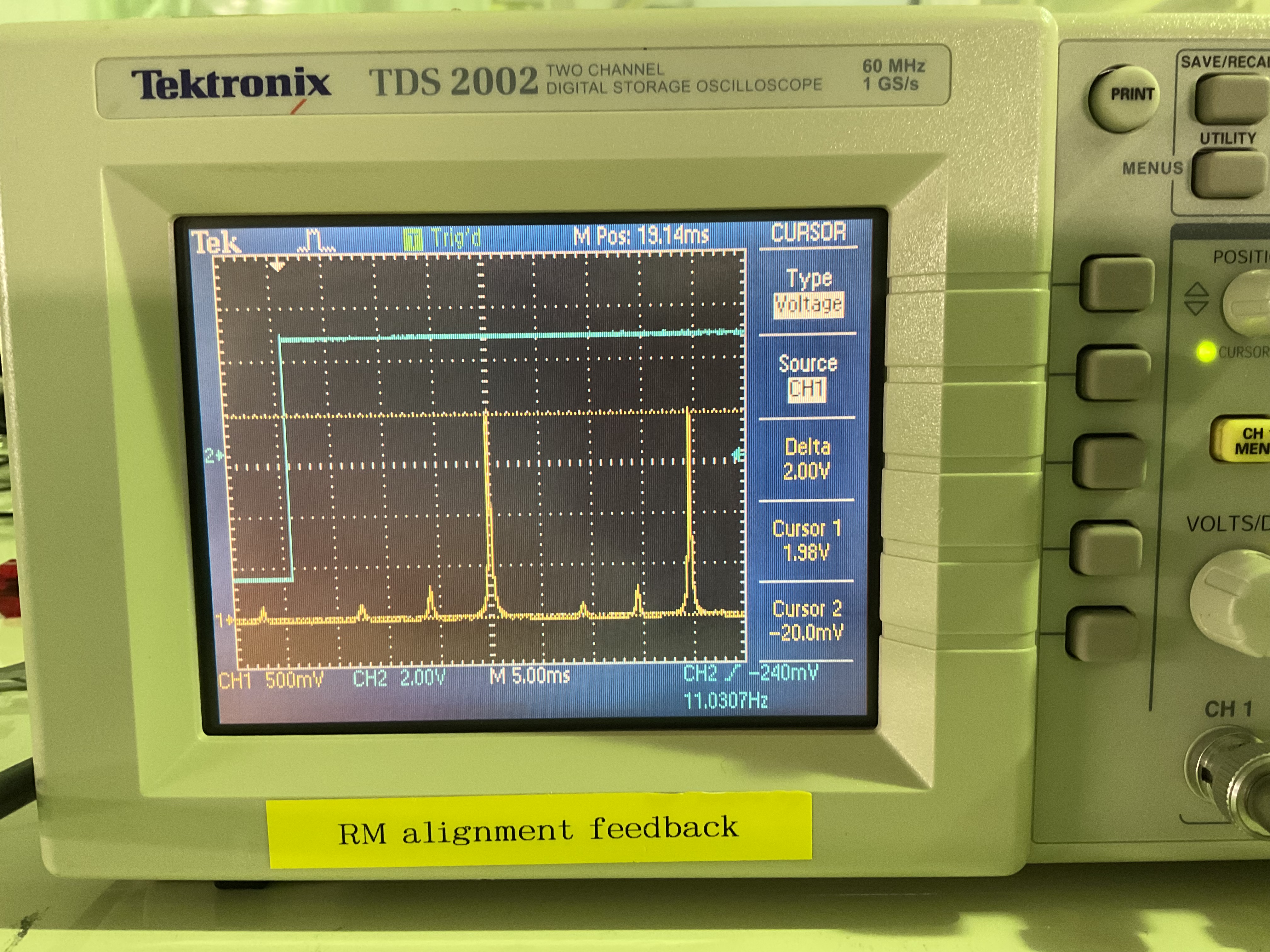
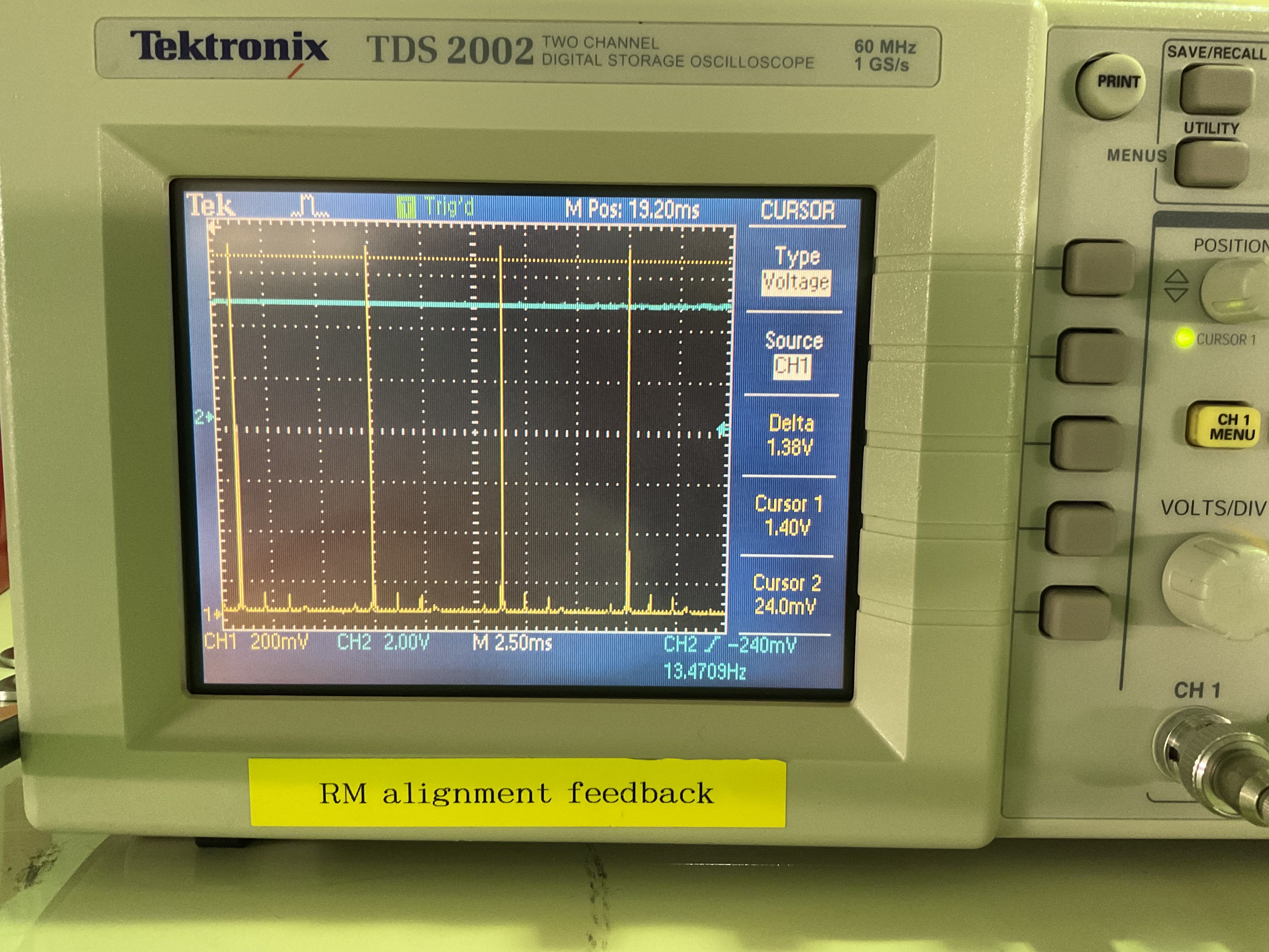
It turned out that for the CC the spectrum analyzer was just being weird for some reason, and when I changed the frequency settings a few times it showed the PLL sidebands. For ppol, the power supply to the fiber PD that sends the beat signal to the servo was unplugged (not intentionally as part of the scheduled recent electrical shutdown - rather, the connector is quite loose). The signal ppol Beat in becomes - 6 dBm (ok). I loaded the most recent PLL settings in the computer without any changes (20241115PLLCC.txt and same date for ppol, fig 1 and 2, CC is ADF4001) and both PLLs could lock (monitor channel references fig 3 and 4).
Green generation
The SHG became extremely misaligned (fig 5) since I last looked at it before going to Australia (fig 6, mode matching ~ 89.2%). The SHG normally maintains alignment for a very long time. From the adjustment of the steering mirrors the misalignment was in both pitch and yaw. I aligned to (2060 + 294 + 120 mV) ~ 83.3% (fig 7), I couldn't get the other two peaks down any further. It seems the SHG internal alignment could be an issue eventually but for now it's manageable. Generated green is 300 mW before the green FI and 280 mW before the unused 78 MHz EOM.
The GRMC/MZ assembly was also misaligned, but this is normal since the MZ PZT mirror has never been very stable. I realigned to (1290 + 72 + 54 + 18.4 mV) ~ 89.9% (fig 8). As usual it is currently set for 25 mW stable green to OPO which reads 312 mV on the GRMC TRANSMIS OUT monitor channel. PDH is fine (fig 9).
OPO
I sent ppol to the OPO. The alignment looks nominally ok (fig 10) so I didn't measure the mode matching. ppol mode matching was never particularly critical anyway. However, GRMC suddenly unlocked and was a bit out of phase again. I had thought I fixed this problem by changing the DDS channel but it seems there might still be some issues. I checked the DDS2 DAC0 GRMC DEMOD spectrum to see if it was dirty but it seems fine. I reoptimized the GRMC demod phase from 0 to 335 degrees.
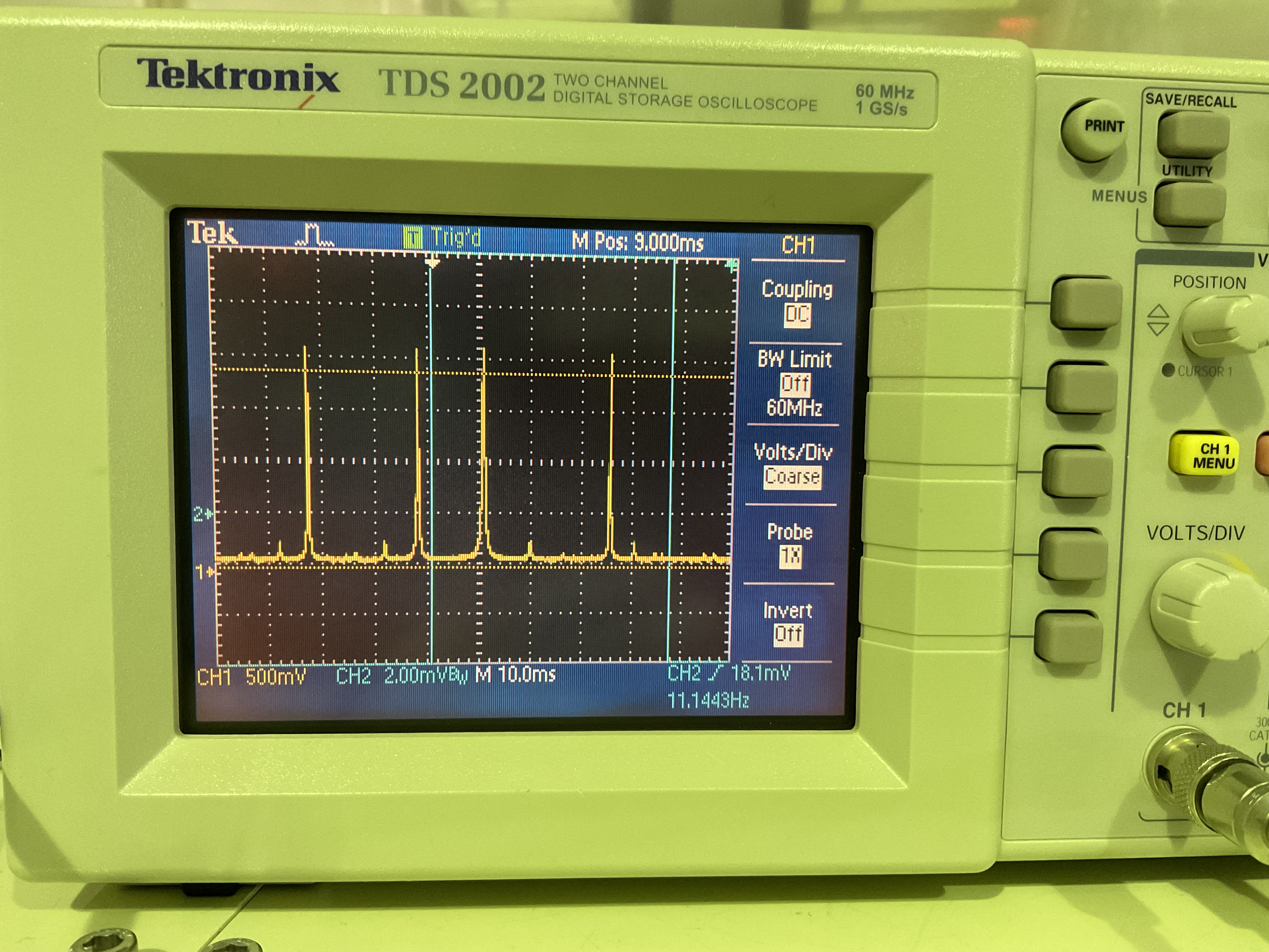
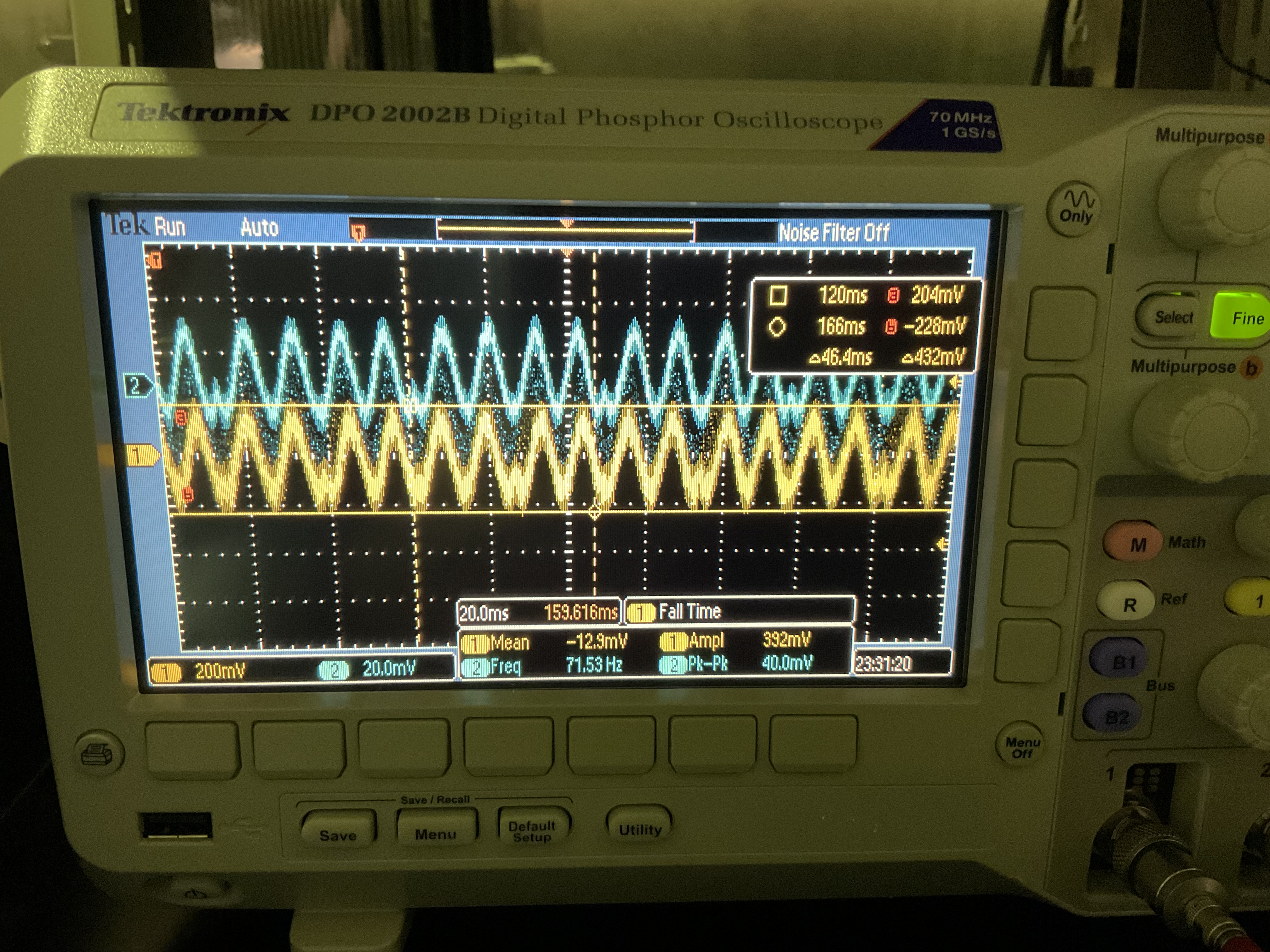
With green going to OPO I applied modulation to green phase shifter to check the CC error signal, which directly indicates the amount of nonlinear gain. As shown in figure 11, when GRPS is modulated the CC1 error signal is sinusoidal and the amplitude is close to when I last looked at squeezing (indicated by the cursors on the yellow trace. Blue is CC2). So it seems the nonlinear gain optimization conditions for ppol PLL frequency and OPO temperature haven't changed much.
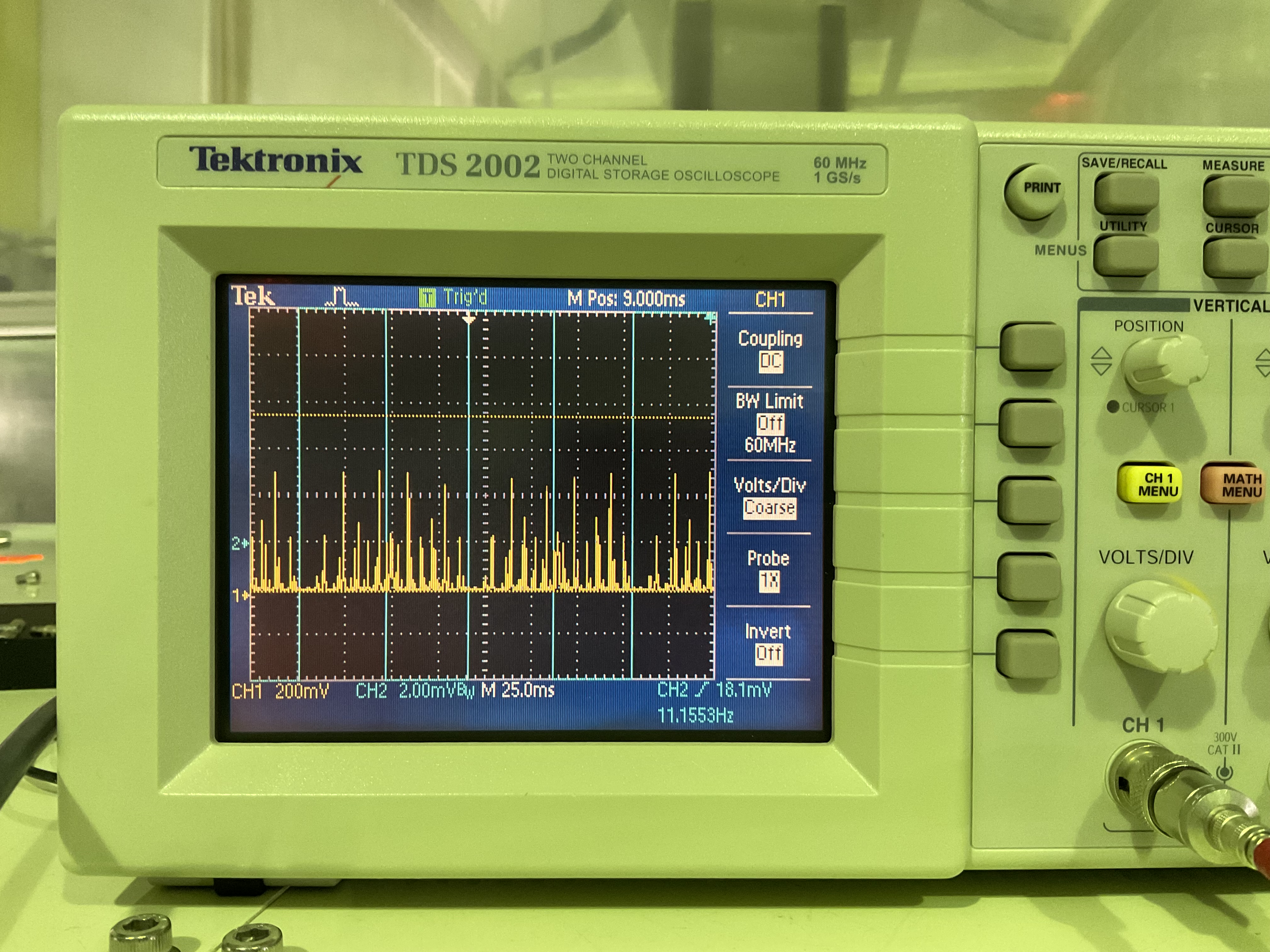
A short time after I observed the CC error signals I saw that they had disappeared. The OPO transmission spectrum for ppol had suddenly become very misaligned (fig 12), without touching anything on the table. Before realigning anything I checked the laser current/temperature (ok) and then tried tapping optics along the ppol path to see if anything was loose (no loose optics at first check). Then I tried to check BAB to OPO using power meter in transmission of OPO with green blocked. The s-pol transmission spectrum seems to have some low background of junk modes, and then I can see narrow BAB peaks going up and down slowly as if the BAB is being amplitude modulated somewhere. It was getting late and I couldn't determine whether or not the BAB was really misaligned to the OPO.
During this process it seems the IRMC keeps good alignment so the main laser and 88 MHz EOM should be fine.