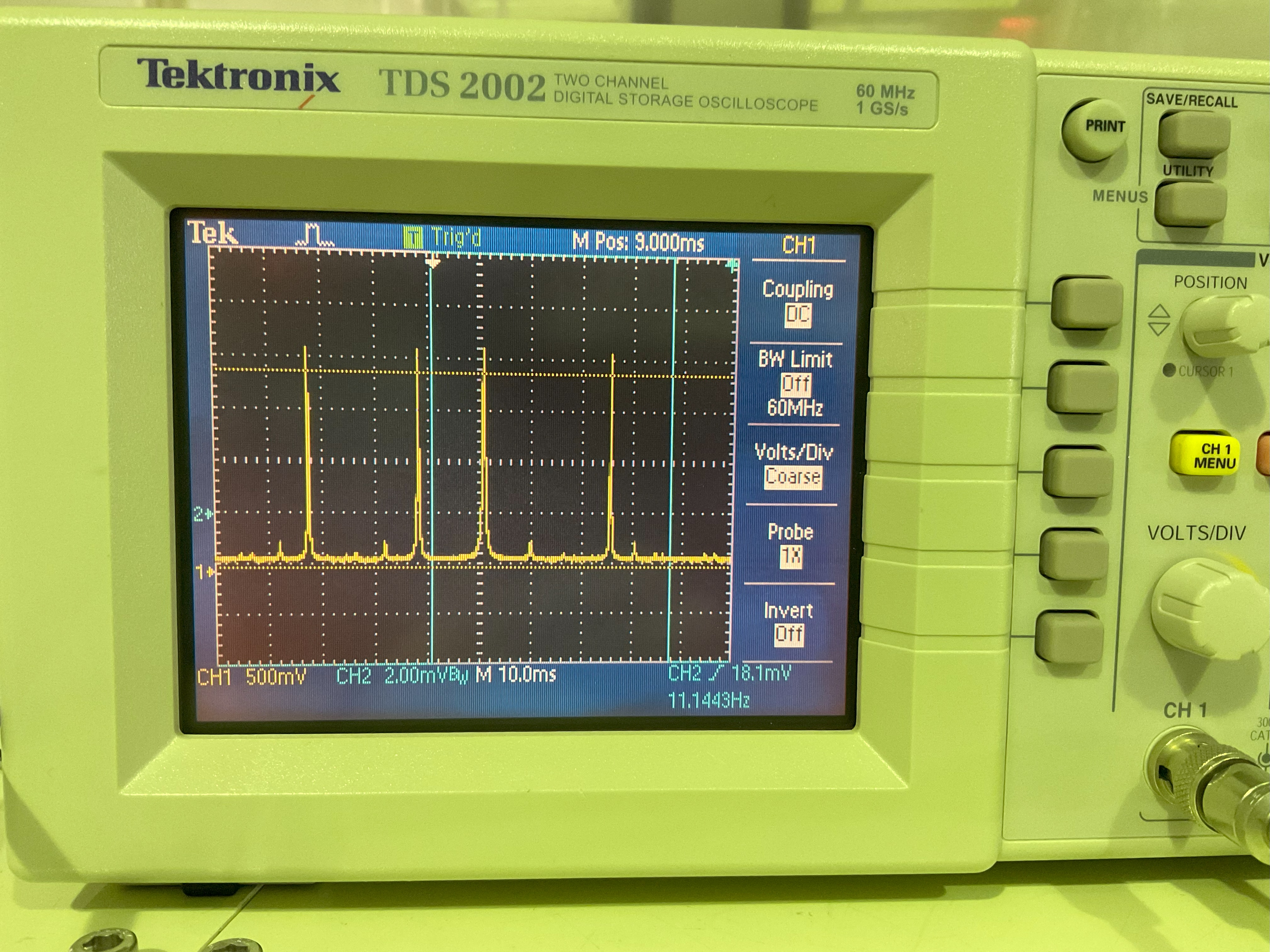
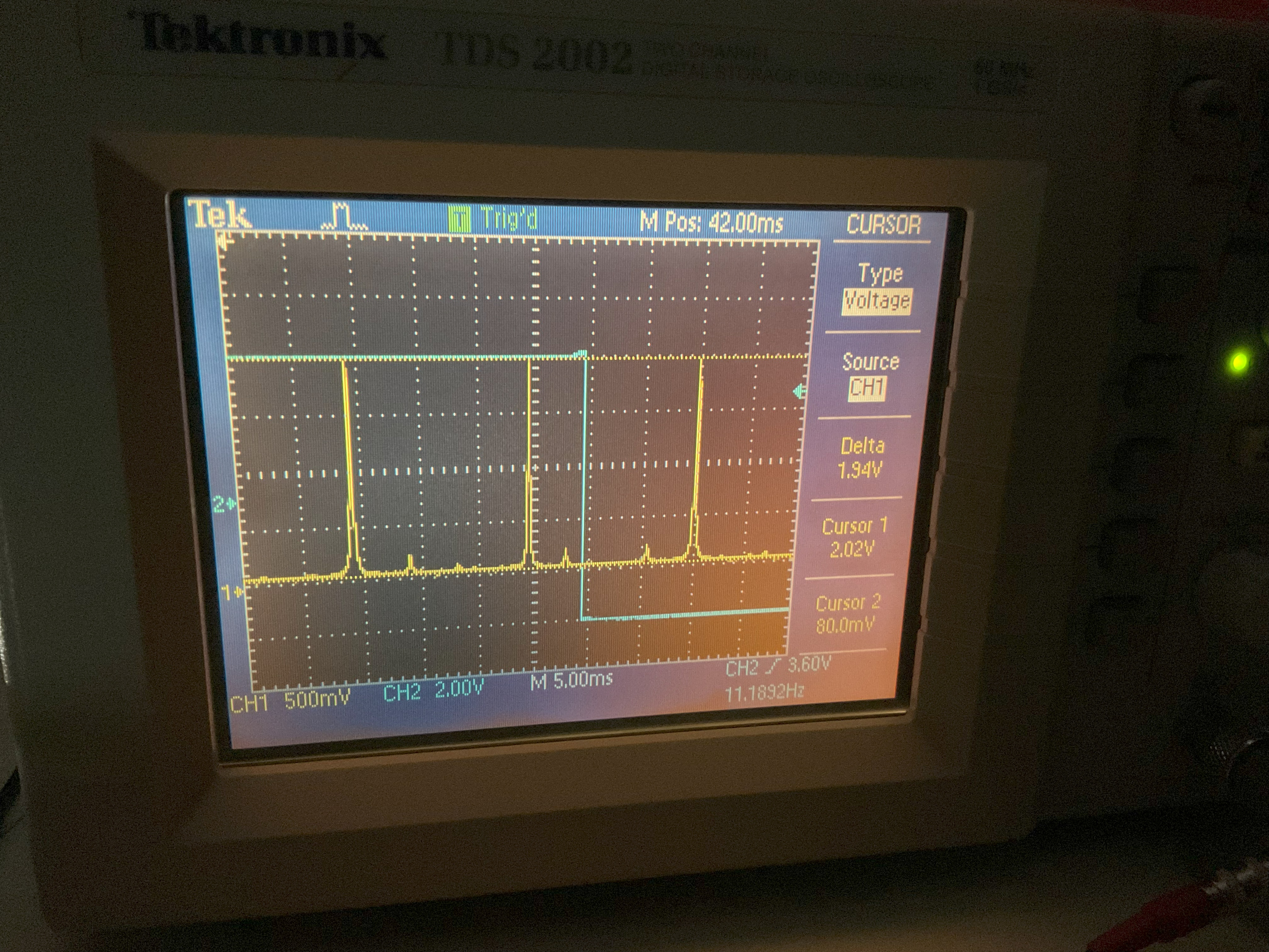
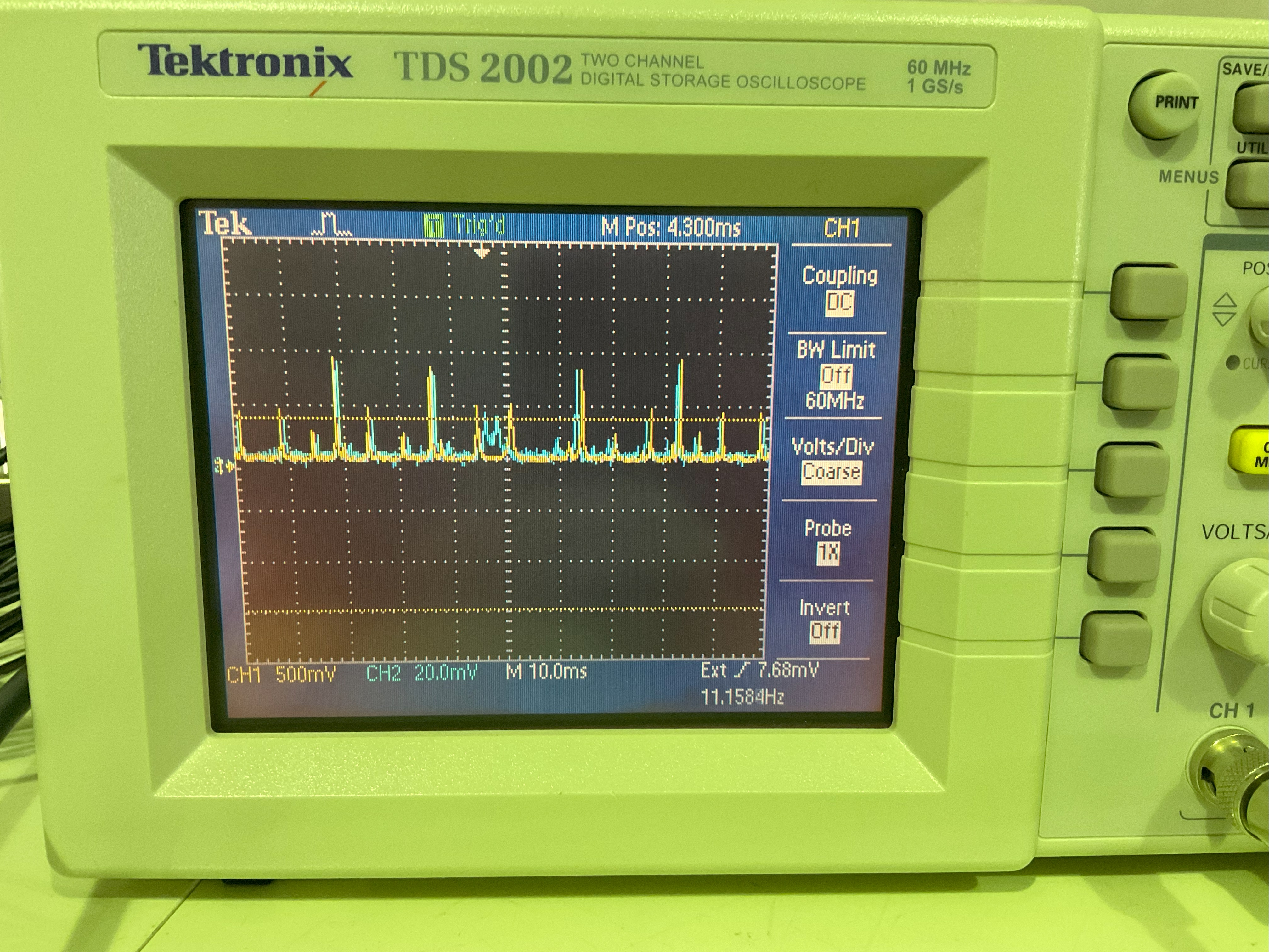
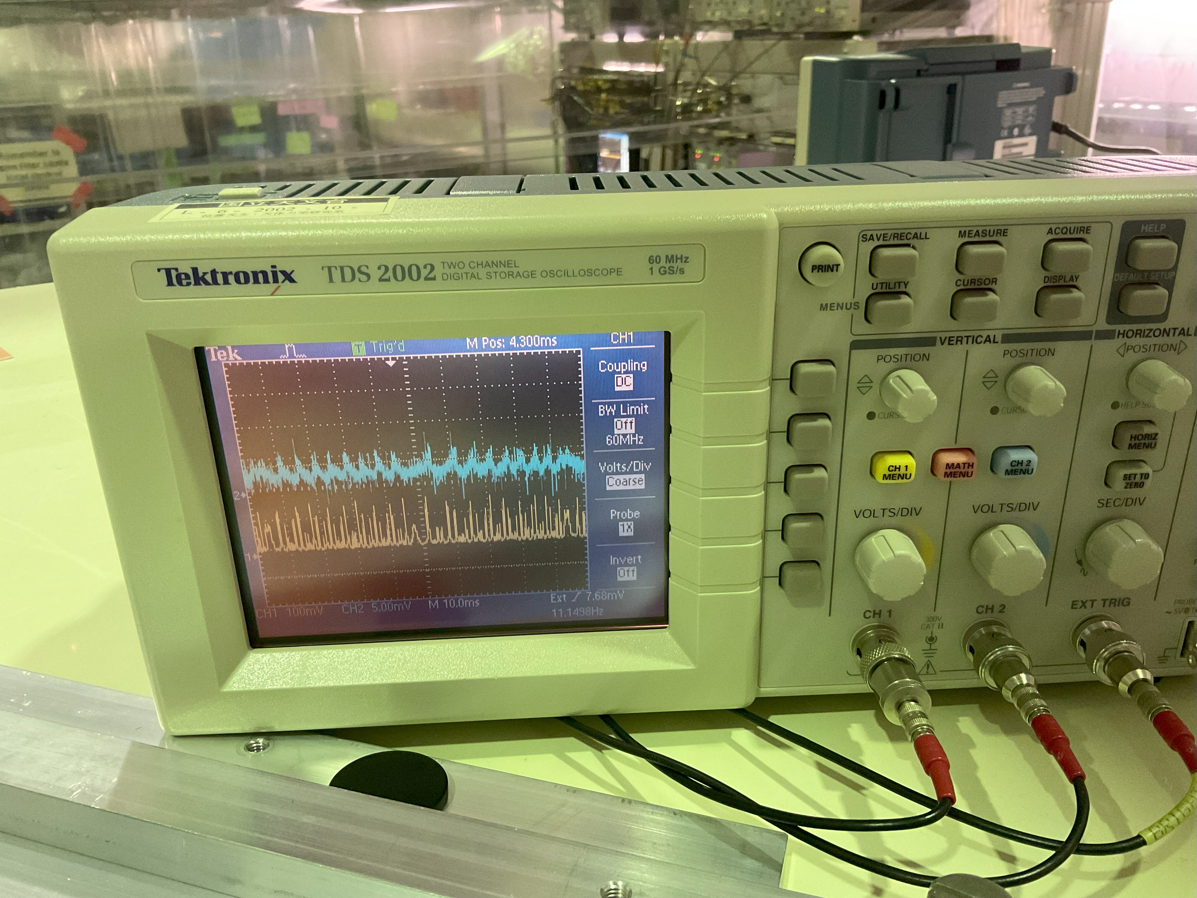
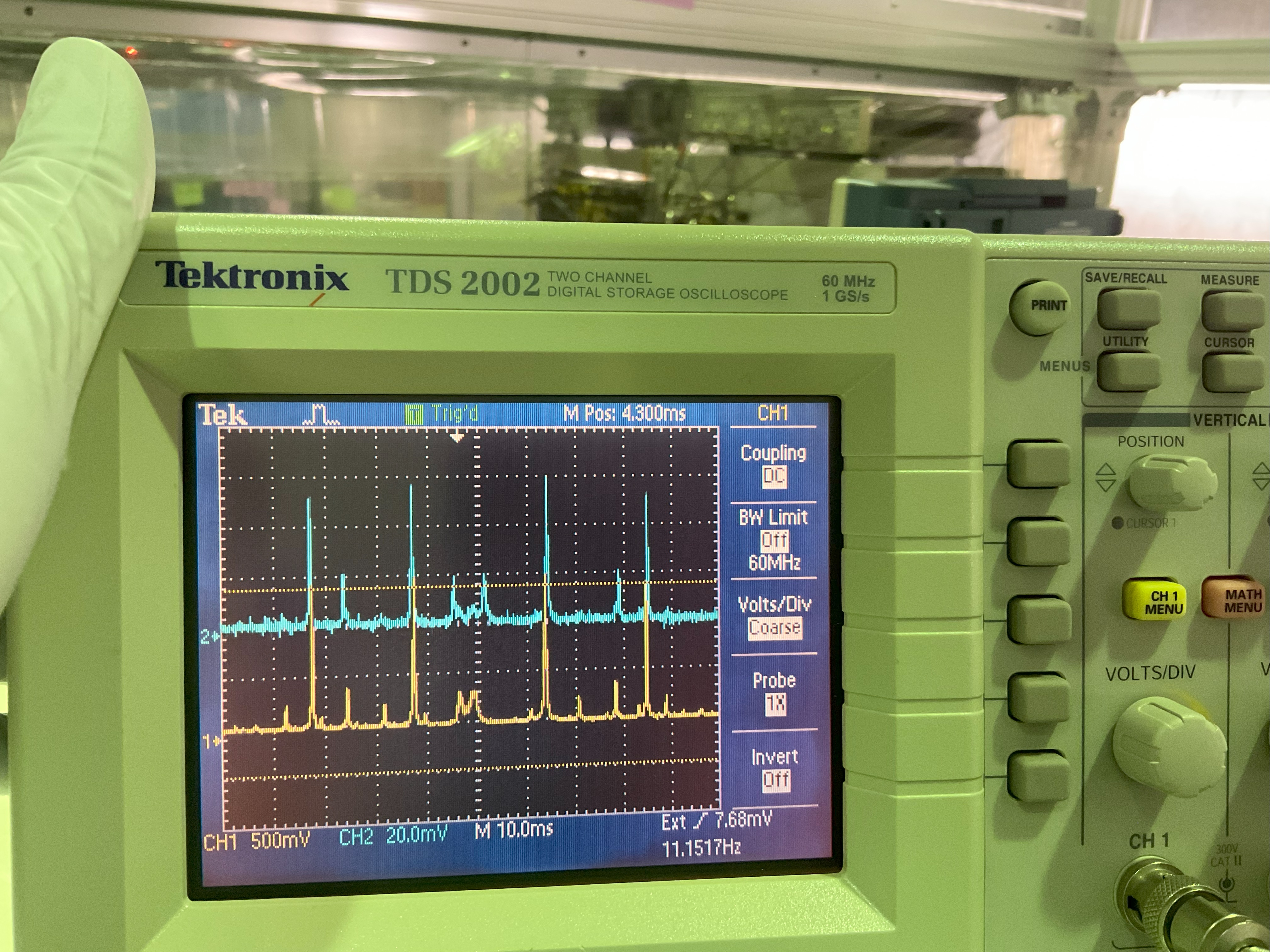
As detailed in elog 4013 the OPO became suddenly misaligned to both ppol and BAB. I still have no idea of the cause. At the time I was producing nonlinear gain with ppol locked, which I could see in the error signal of CC1 and 2, and then while I was preparing to measure squeezing suddenly the OPO had completely misaligned. This is very strange considering the ppol alignment is usually quite stable (fig 1 April 2025, fig 2 November 2024 ppol to OPO alignments for reference). Overlapping the ppol and BAB transmission spectra showed that they had the same misalignment (fig 3 - the difference in the middle of the oscilloscope screen is just due to the PZT scan range not covering the full width of that particular peak) and by tapping stuff I could see that the OPO input mirror plate was the most likely culprit.
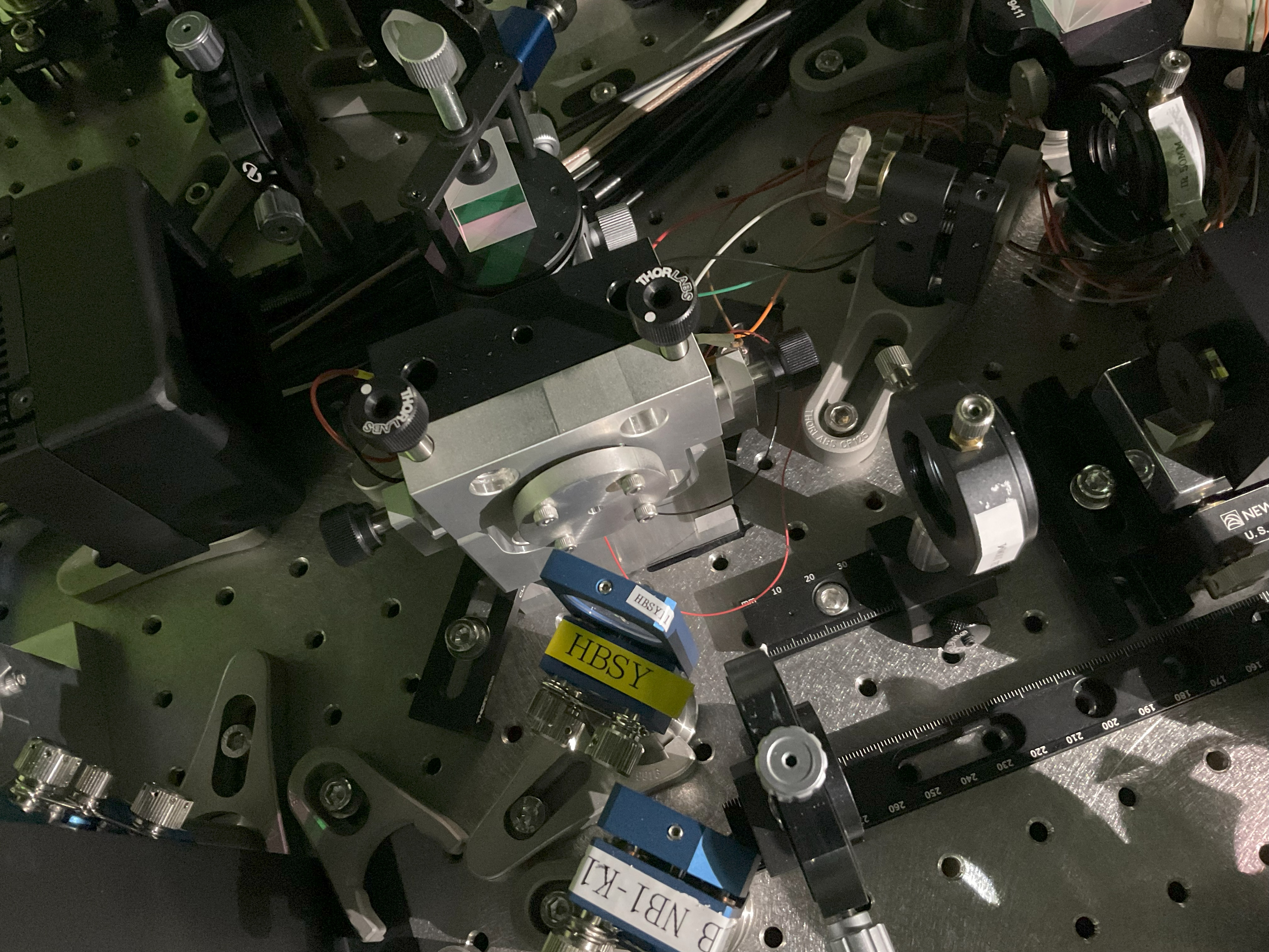
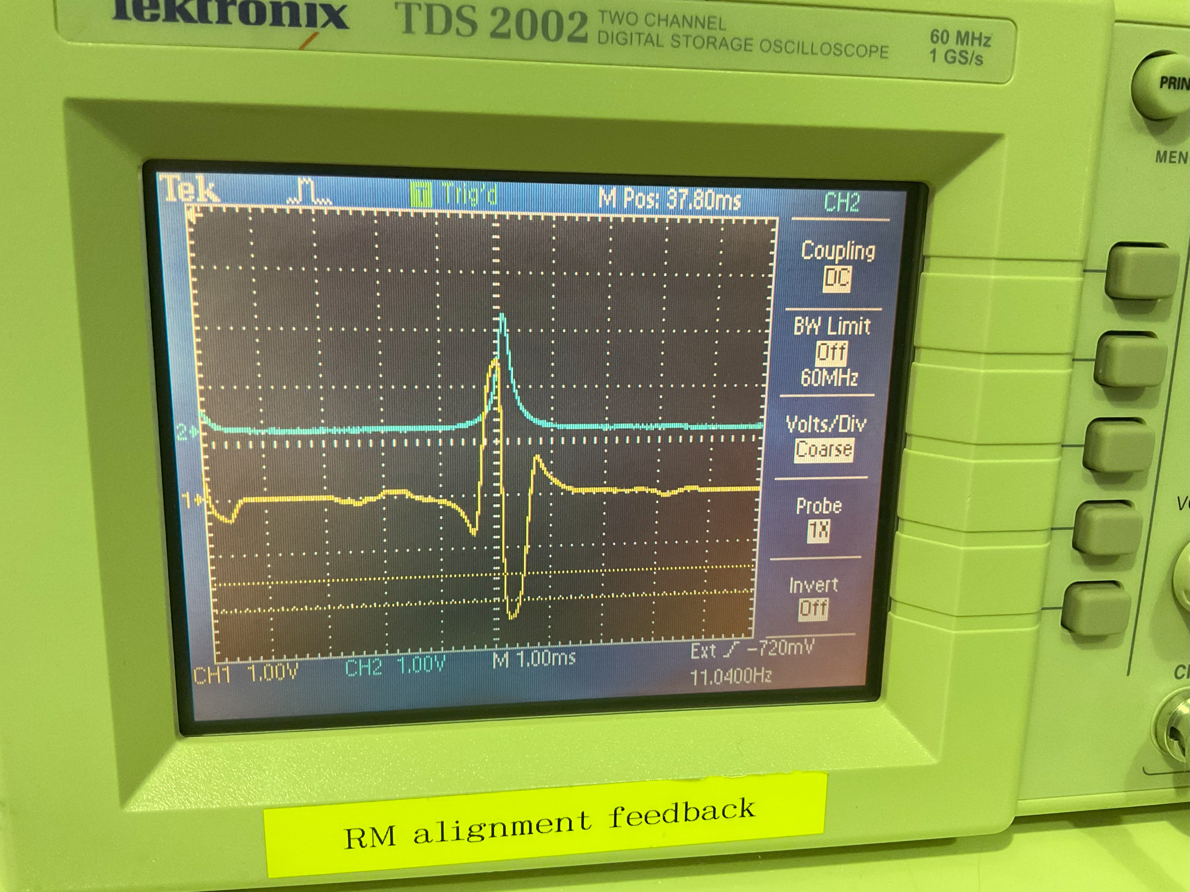
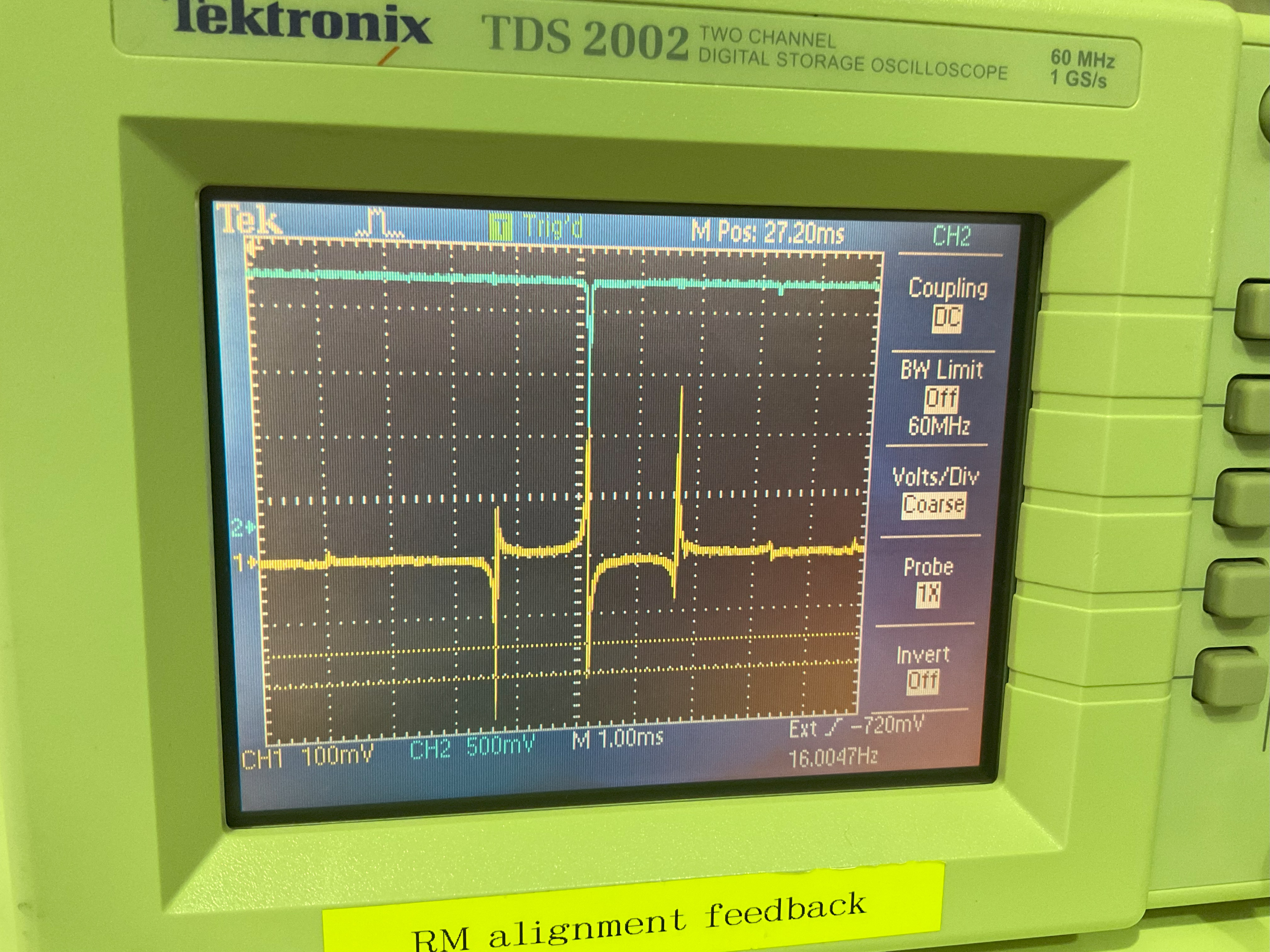
Between that post and now I had tried to adjust the screws on the input plate (fig 4) to see if that affects the alignment spectrum, but this had the effect of just moving the transmission mode peaks across the oscilloscope screen. Basically just scanning the cavity length. After that inconclusive endeavour I had to try more carefully, especially as the alignment was quite bad (fig 5)
Matteo's thesis gives an outline of the procedure to align a nonlinear cavity. First, the crystal must be internally aligned to a reference beam using targets, and then the input mirror (meniscus) must be moved perpendicular to the beam to find the place with the best transmission spectrum. Since I did not suspect the crystal to be misaligned, I tried just starting from the step of finding the good alignment of the input mirror. By loosening the screws holding the input plate and moving it I tried to find the good alignment (the input mirror is slightly loose under the input plate and can move very slightly in x and y). In doing this I could find a mirror position with very good mode matching, however, I found it to be hard to fasten the input plate while keeping the good mode matching. I could fasten the input plate to maybe 75% mode matching (fig 6). I could occasionally see the spectrum pass by the optimal condition (~ 90%) but I could not sufficiently fix the input mirror to this condition.
Eventually the transmission spectra for both beams disappeared. I was worried the PZT might have broken so I sent a few kHz signal to the PZT HVD. The PZT was whistling and the pitch changed when I changed the input frequency, so it's not broken. In the end I concluded that the beam to OPO crystal alignment may have messed up as well. The OPO case feels very tightly held to the table, yet I might have pressed something too hard anyway. It looks like I now have no choice but to do full realignment of either this OPO or the new one. I really hate that this had to happen when I felt like I was quite close to recovering stable FIS (> 30 min sqz) across all green pump powers (up to 60 mW), and the worst part is I still have no clue as to how the OPO suddenly misaligned in the first place.
In some other nonrelated events, it seems the SHG error signal disappeared at one point. However, this was because the cable connecting the power supply of the PDH PD was a bit loose (I had the same problem recently with one of the fiber PDs). I attached SHG, IRMC error signals (fig 7, 8) for 70 degrees phase in DDS1 DAC1 (IRMC/SHG DEMOD). I guess I have to find some short cables to change the IRMC electronic path length again.