NAOJ GW Elog Logbook 3.2

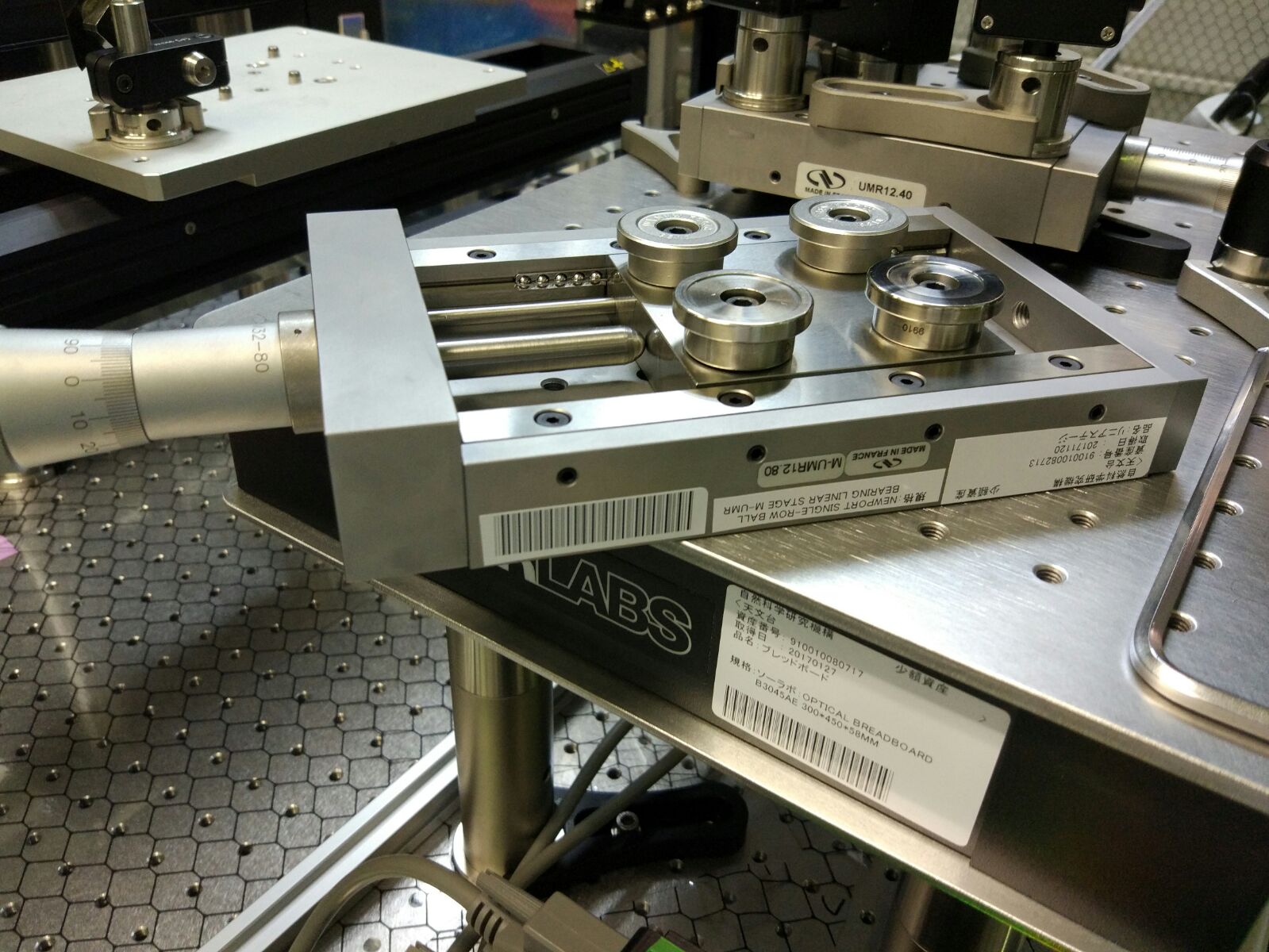
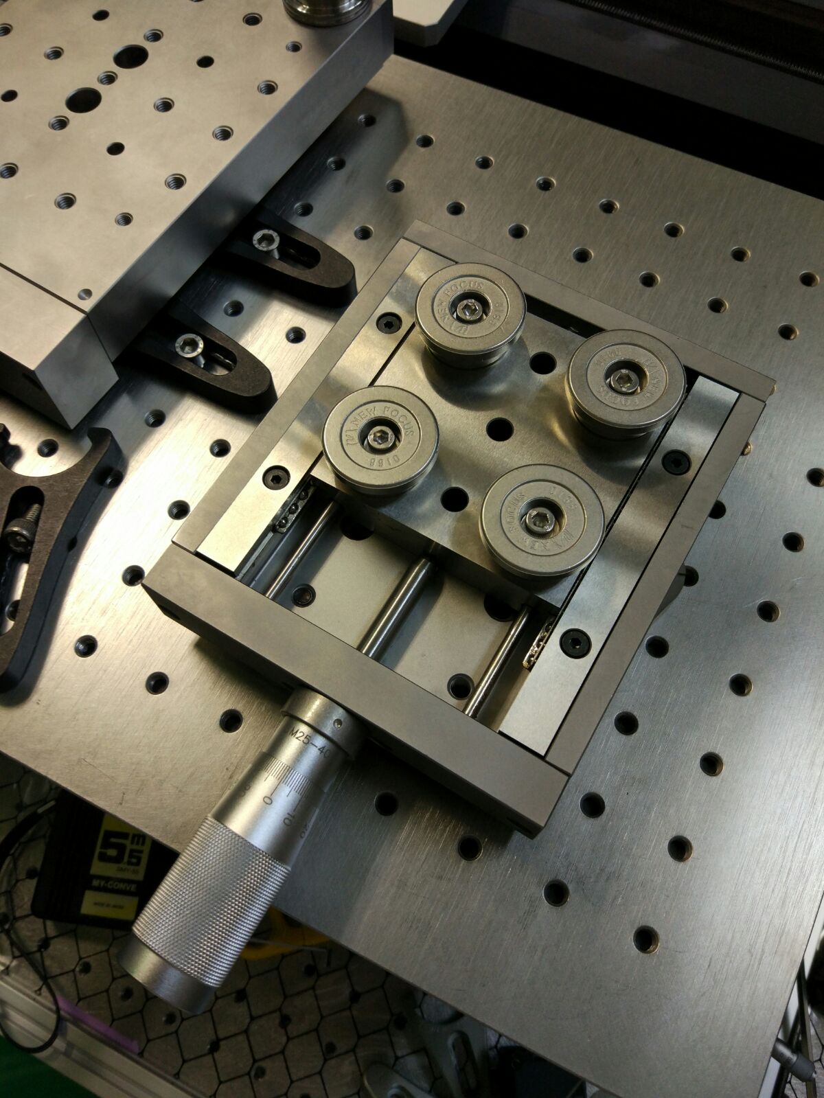
I screw 4 short pedestals below the M-UMR12.80 linear stage for the HeNe imaging unit, I clamped it with 4 forks on the breadboard to be parallel to the beam.
Since there was not enough space for the forks, I had to move the hole breadboard by a few cm.
I did the same with the other linear stage UMR12.40 for the 1310nm probe. Since it is imperial, I had to look for a set of 4 imperial screws in ATC.
All the parts I used, I washed them in the ultrasonic bath in ATC. Except for the stages themselves because the bearings have grease, so better not to wash them.
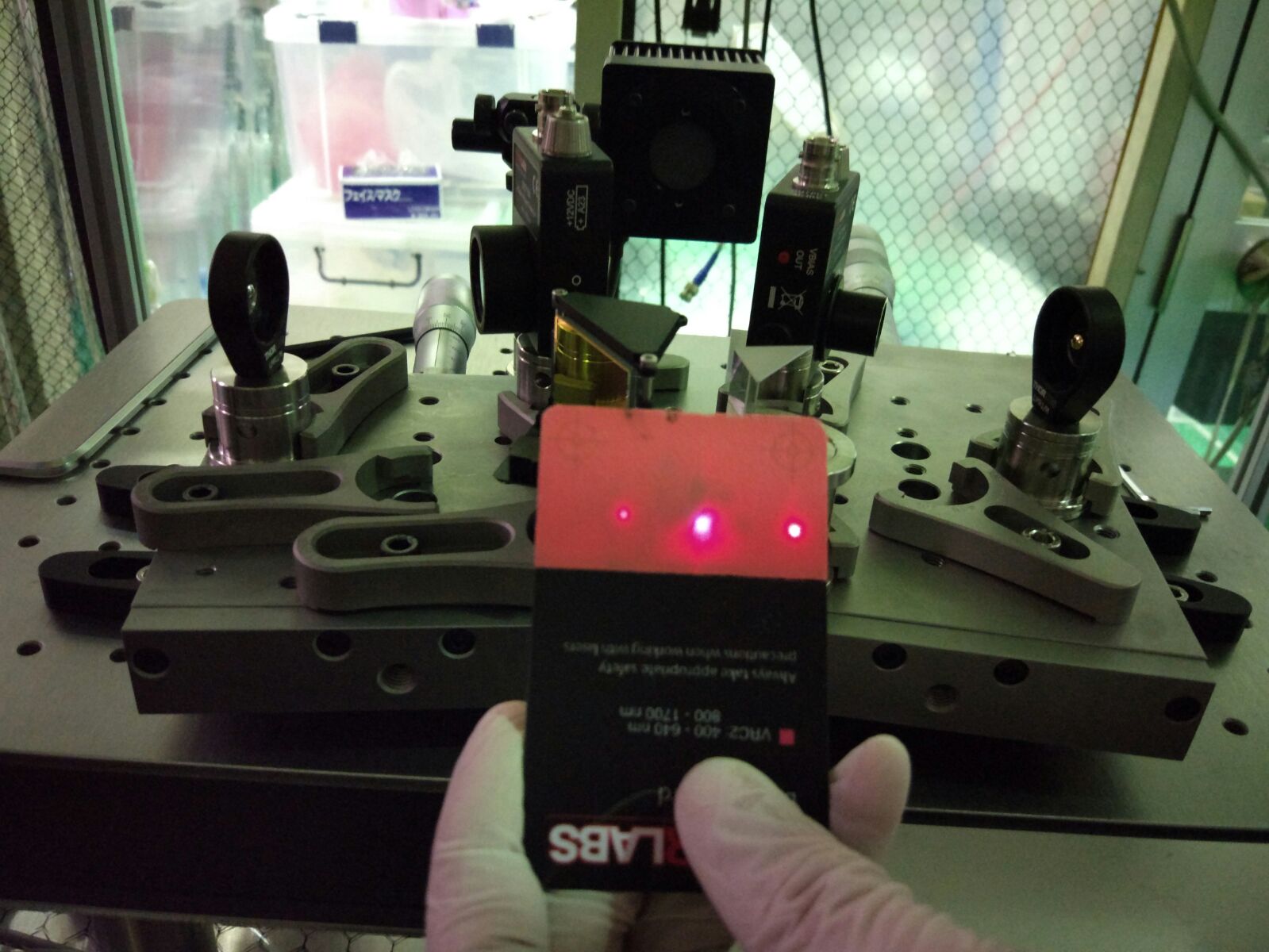
after moving alle the optics of the IPC I had to realign the pump laser beam on the pinhole (at the reference position of the cross point).
First I adjusted the height of the beam on the optical table from the IPC to the periscope (128mm)
Then I removed the last focusing lens on the optical breadboard (after the periscope).
I used two positions of the pinhole along z (max and min position limits), and maximized the power transmitted by the pinhole. I moved back and forth the translation stage on those positions. On the closest position I adjusted the second stearing mirror, on the further position I adjusted the periscope mirror. For the first rough alignment I also used an optical cross.
Now the beam is parallel to the z axis of the translation stage. Then i put the last focusing lens back on its mount and I adjusted the lens position to have the maximum power transmitted by the pinhole.
Since I had optimized the IPC, now, in order to have 30mW on the imaging unit table with 0.8A of laser current, the half wave plate have to have an angle of about 22deg (before optimization it was 0deg)
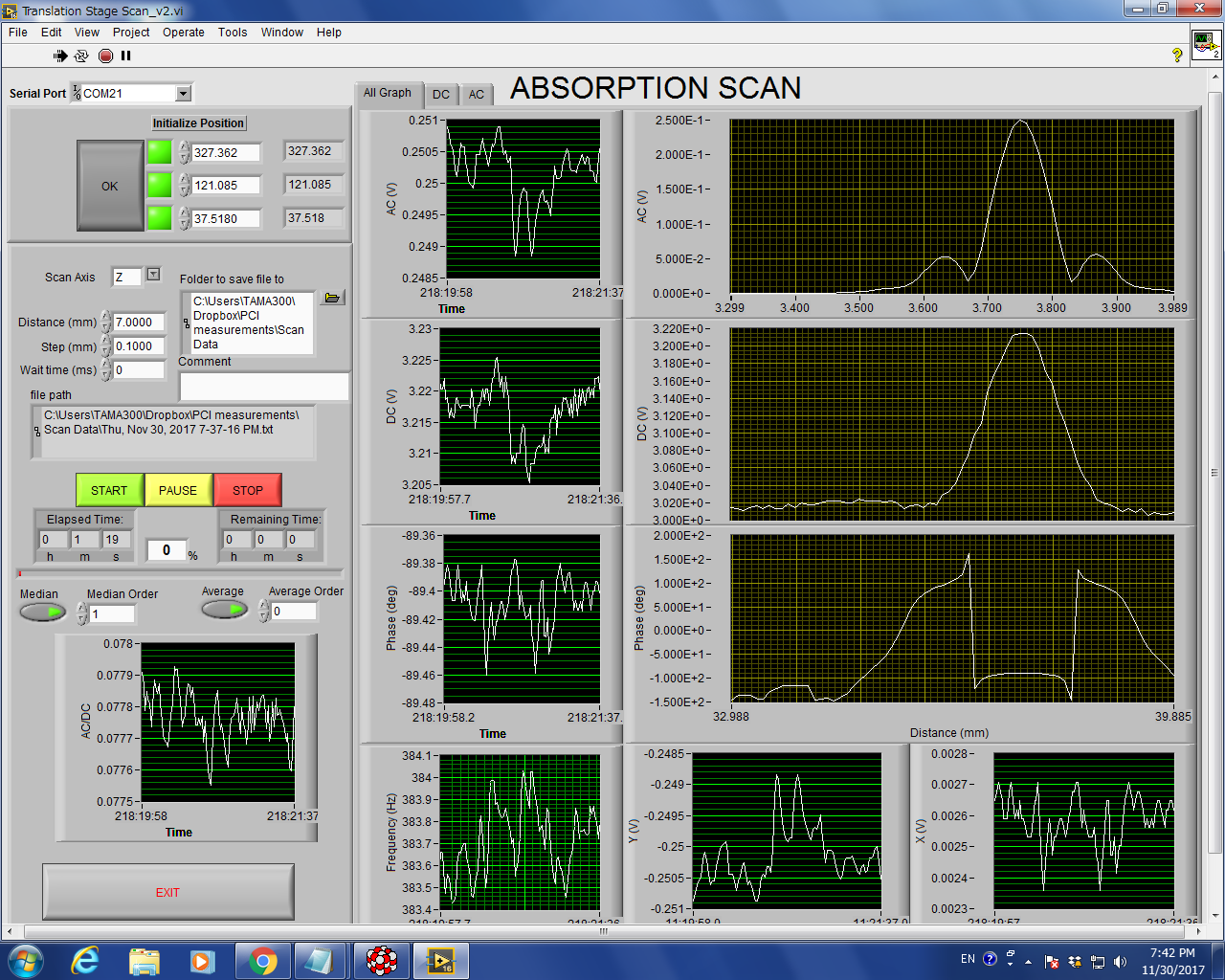
Then I made a scan of the reference sample with the HeNe Imaging unit, and when I went to optimize the maximum of the AC scan (adjusting the pump focusing lens position) I found that it was already at the maximum.
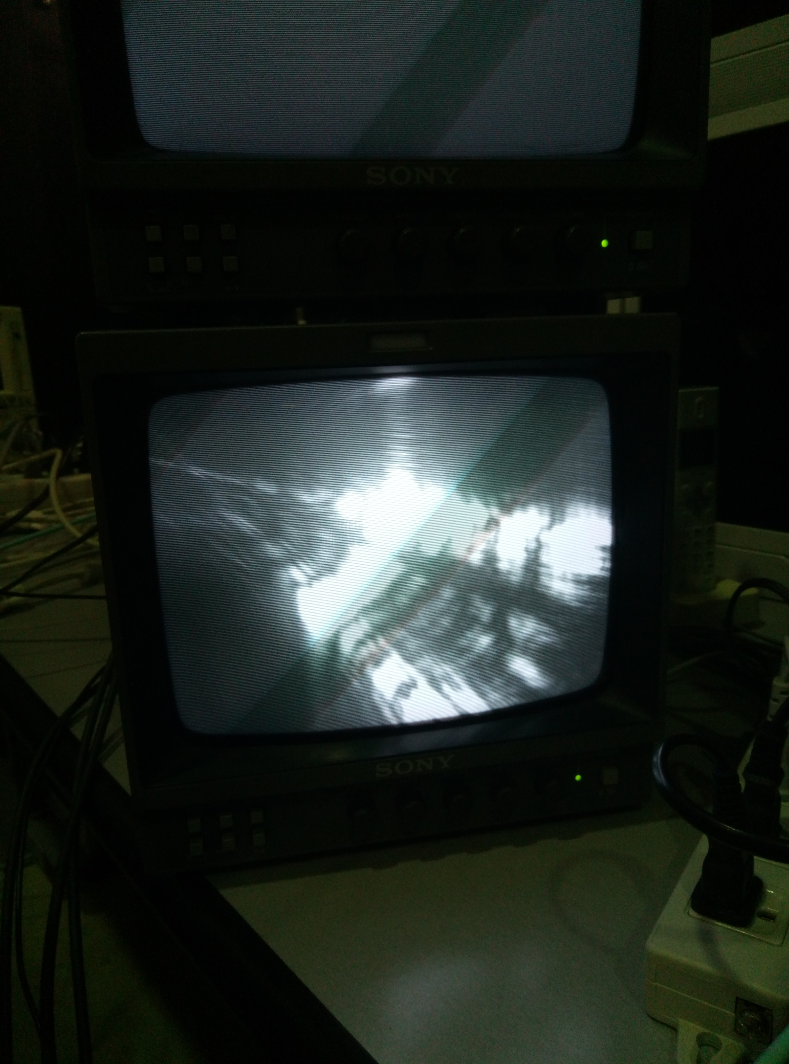
In the video, we can see the whole halo. But if you check something in the halo, you will find there is only something like the fiber.
I attach the video as following.
https://drive.google.com/open?id=18PApeToBRHC-tDisKg--beNVbhRKi0-E
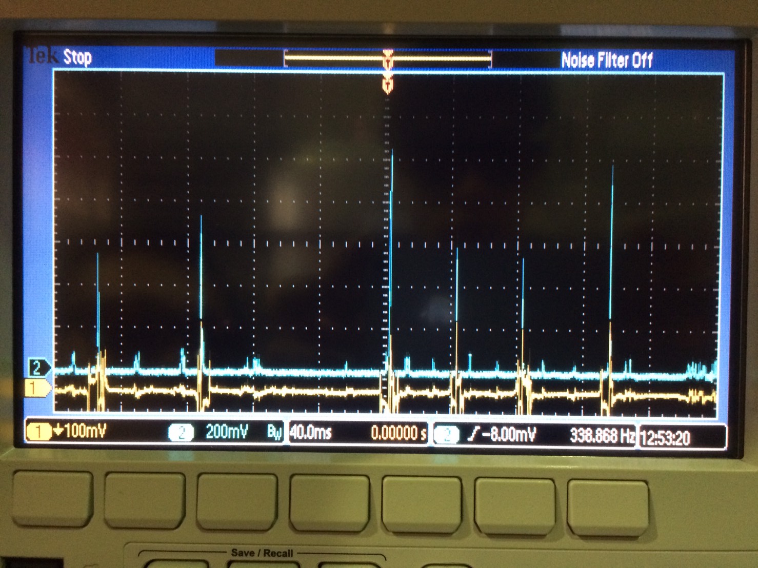
Firstly, we try to lock the cavity with green beam. The height peak is 1V. After locking the transmitted signal is also 1V. We didn't change anything else but the EOM for filter cavity.
(Because we need to put a case on the top of our bench. The base plate of EOM for filter cavity excesses the boundary. So we change the base plate angle and align it agin.)
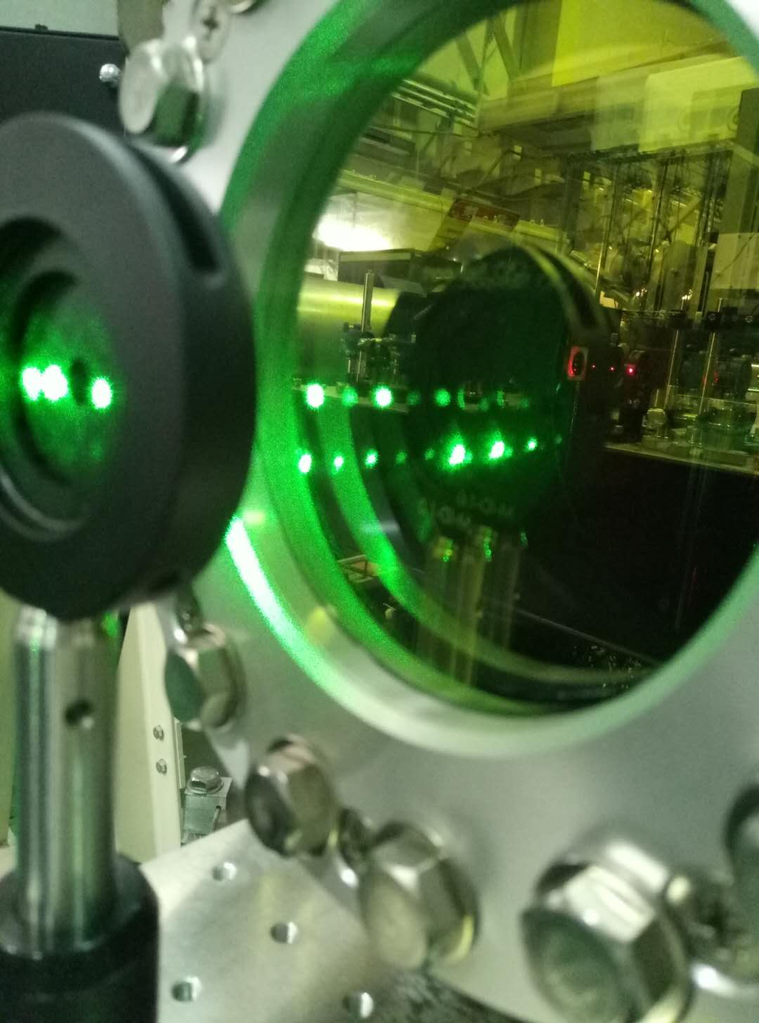
Secondly, we follow the procedure of yuefan. We made sure the laser hit on the right position of the membrane of PR chamber. And we also change the height and angle of camera. Then we can see the signal as attached. We supposed that it's the halo as yuefan mention in the procedure. We tried to moved the camera around to find the laser point and we failed. Note here, we can see only a part of the halo. That means we can see only the shape as a sector. I think the reason maybe the incident angle. And I tried to change the incident angle, but find nothing more. I will try to figure out how to find the beam tomorrow.
Keeping the high-power laser current at 0.8A we have 420mW right after the fiber output.
Today the best I could get from the IPC was a power maximum and minimum (as a function of the rotation angle of the halfwaveplate) of:
Right after the IPC
407mW (max)
15mW (min)
On the imaging unit breadboard (after all the optics on the path, including the chopper)
190mW max
3mW min (comparable with the power-meter sensitivity)
In order to get 30mW (the power we usually use for calibration), I increased the laser current up to 1.3A
In order to notice a waist difference (in the absorption signal) between low and high current, we have to be able to have 30mW with high current. I think we have to get the IPC better optimized, or, if not possible, we need to add another IPC
With Matteo, we worked on the red probe last week
before replacing the linear stage with the longer one, we checked what's the maximum signal we could get in this condition
we moved the linear stage to find the max of the AC/DC signal. As usual, everytime we moved the linear stage, we maximize the DC
- Pump laser current= 0.78, power= 30mW
- Reference sample surface
- DC max=3.15V
- AC/DC max =0.061
-------------------------------------------------------------------------
Pump laser polarization
With Kuroki, we put a cube PBS right after the output fiber and measured the p and s polarization powers with the high-power power-meter
laser current 0.8A
420mW total power
325mW s-polarization
6-10mW p-polarization (power meter not very sensitive at this low power)
-------------------------------------------------------------------------
Input Power Control
we put the half wave plate in front of the output fiber to rotate the polarization into p. Then we adjusted the angle of the first plate PBS to minimize the reflected beam.
Result: minimum of reflected (p-polarized) = 19mW (transmitted400mW)
The strange thing is that the angle is about 64deg, much larger than 56deg
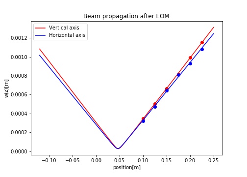
Vertical: w0 = 2.67e-5 m, z0 = 4.73e-2 m
Horizontal: w0 = 2.77e-5 m, z0 = 4.62e-2 m
where w0 is the spot size at a beam waist and z0 = a position of the beam waist.
I put a power meter right in front of the output fiber of the pump laser and characterized the laser power as a function of the current.

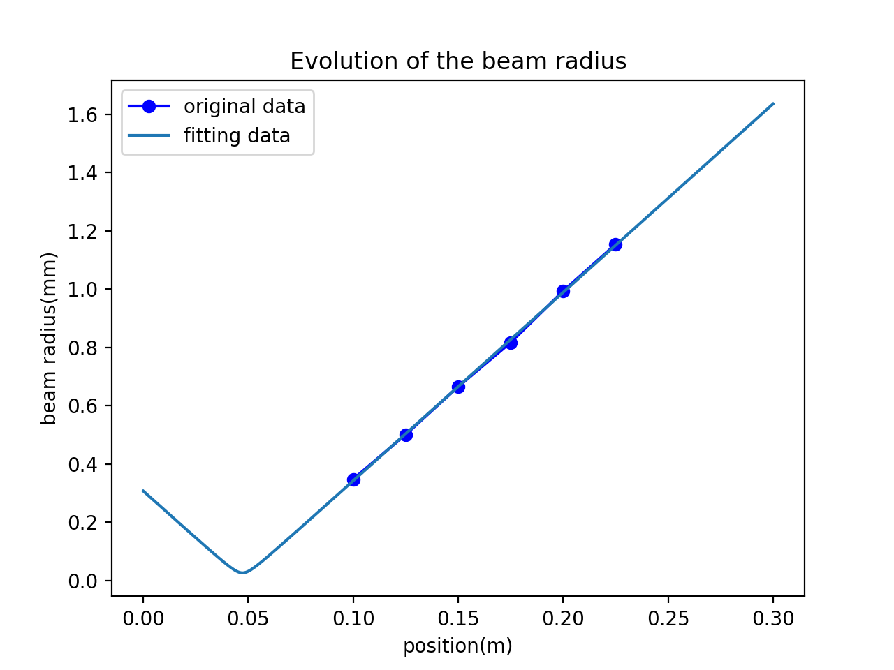
The beam waist is 2.61667926e-05(m). We set the position of EOM as origin, the position of beam waist is 4.72853283e-02(m).
For details, please refer to the figure attached below.
Vertical: w0 = 2.67e-5 m, z0 = 4.73e-2 m
Horizontal: w0 = 2.77e-5 m, z0 = 4.62e-2 m
where w0 is the spot size at a beam waist and z0 = a position of the beam waist.
Three days after FC pump shutdown on last Saturday, we checked the filter cavity locking system. Soon the whole system recovered properly and the cavity was locked. Note that the transmission power while being locked was improved after we changed the demodulation phase. Now it is around 8.0V while it was 4.0V before.
Preparing for installation of coverage on the optical bench, we are changing positions of some optical components. We changed the main laser position slightly. Fortunately, it did not cause problems. One thing we want to notice is that we now have only two clamps fixing laser onto the bench because of lack of space. We do not recommend you to touch laser body.
After two days without pumping the pressure in the tube close to the IM was approx. 5mbar, while close to EM it was approx 0.5mbar.
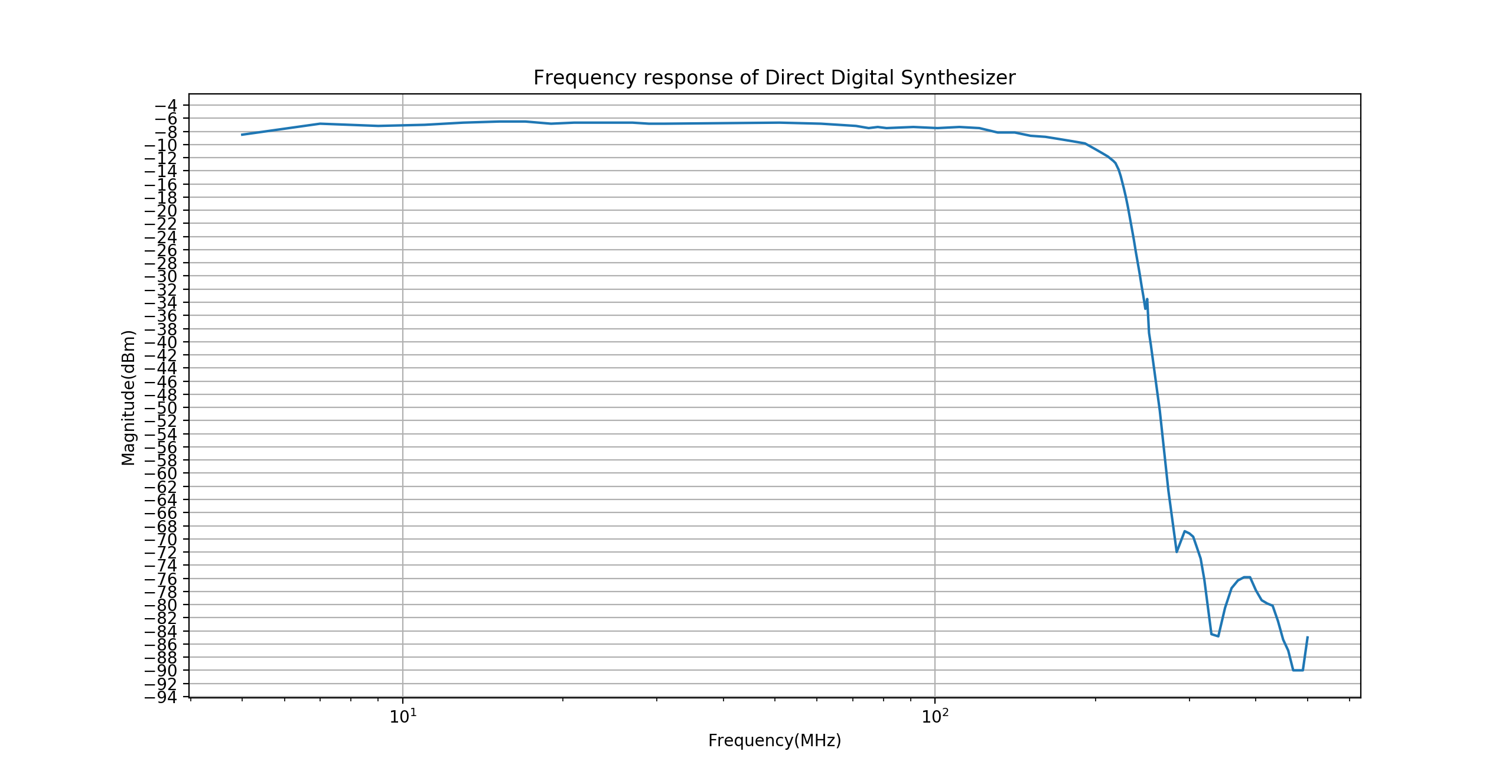
We found on the electronic board of DDS that there is port for non-filter output. So we did some measurement. Although we can detect some signals, like -78dBm or -83dBm. It really means there is no effective output. The signal we detected is the signal leak from other channels.
2.Radio Frequency(RF) signal parameter
RF for Second Harmonic Generator(SHG): Frequency is 15.2MHz, Amplitude is 799mV(pp)
RF for Filter Cavity(FC) demodulation: Frequency is 78MHz, Phase is -0.08, Amplitude is 8.5V(pp)
RF for FC modulation: Frequency is 78MHz, Phase is 109.16, Amplitude is 1V(pp)
RF for Acoustic Optical Modulation(AOM): Frequency is 110MHz, Amplitude is 11dBm.
Amplifier for AOM: Mini Circuit ZHL-2(the gain according to data sheet is around 18dB)
3.Locking measurement
We accept the suggestion of yuefan to check the beam size. And we can see the peak value of transmitted power is around 1.2V as before. The error signal is around 4.7V peak to peak. After locking, the transmitted voltage is around 390mV.
Note here: The first and third value is from the oscilloscope around PC. The second value is from the oscilloscope on the rack. They have roughly 10 times difference for the same signal. We will check later where it is from, like oscilloscope setting or cable difference.
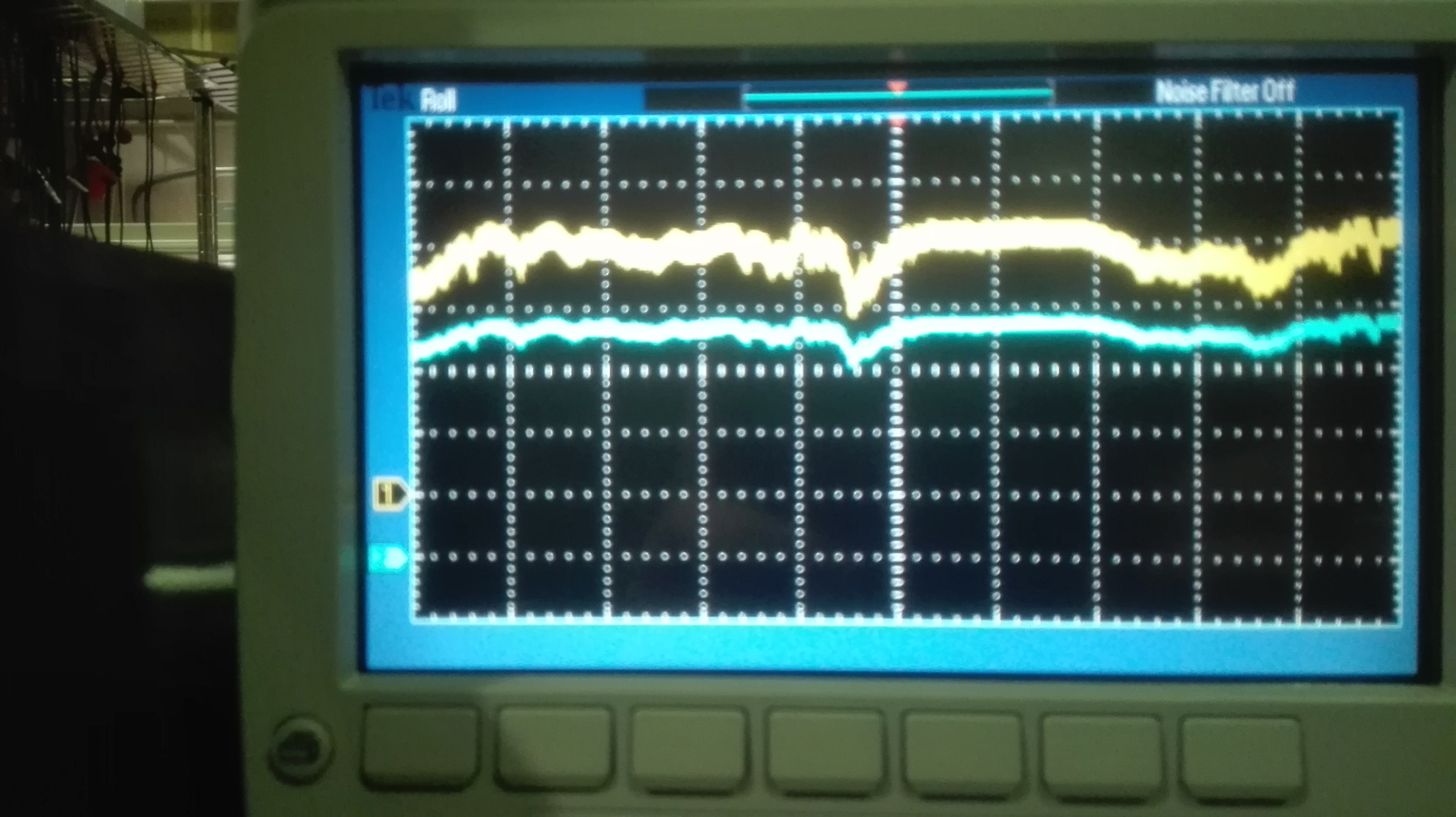
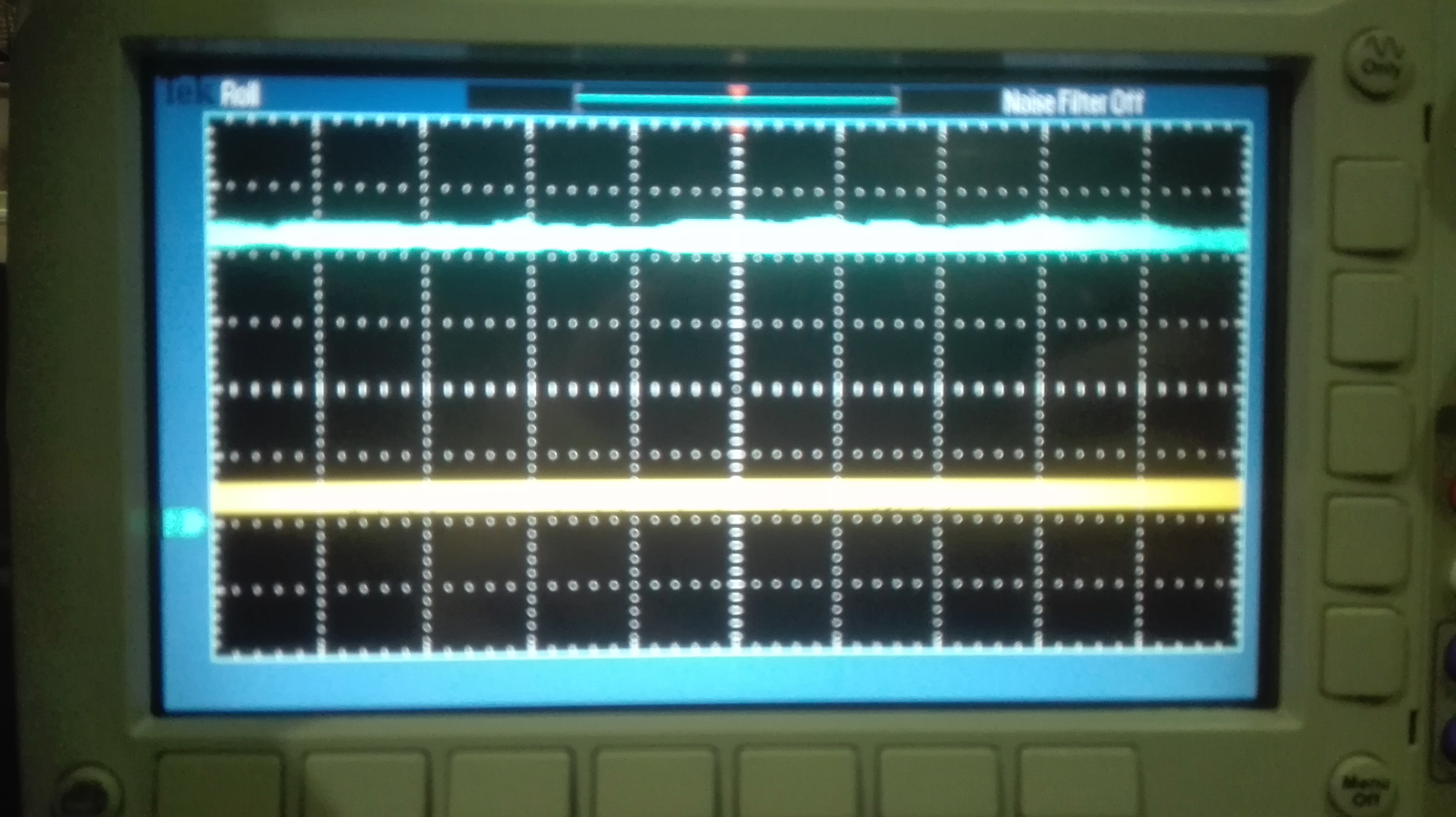
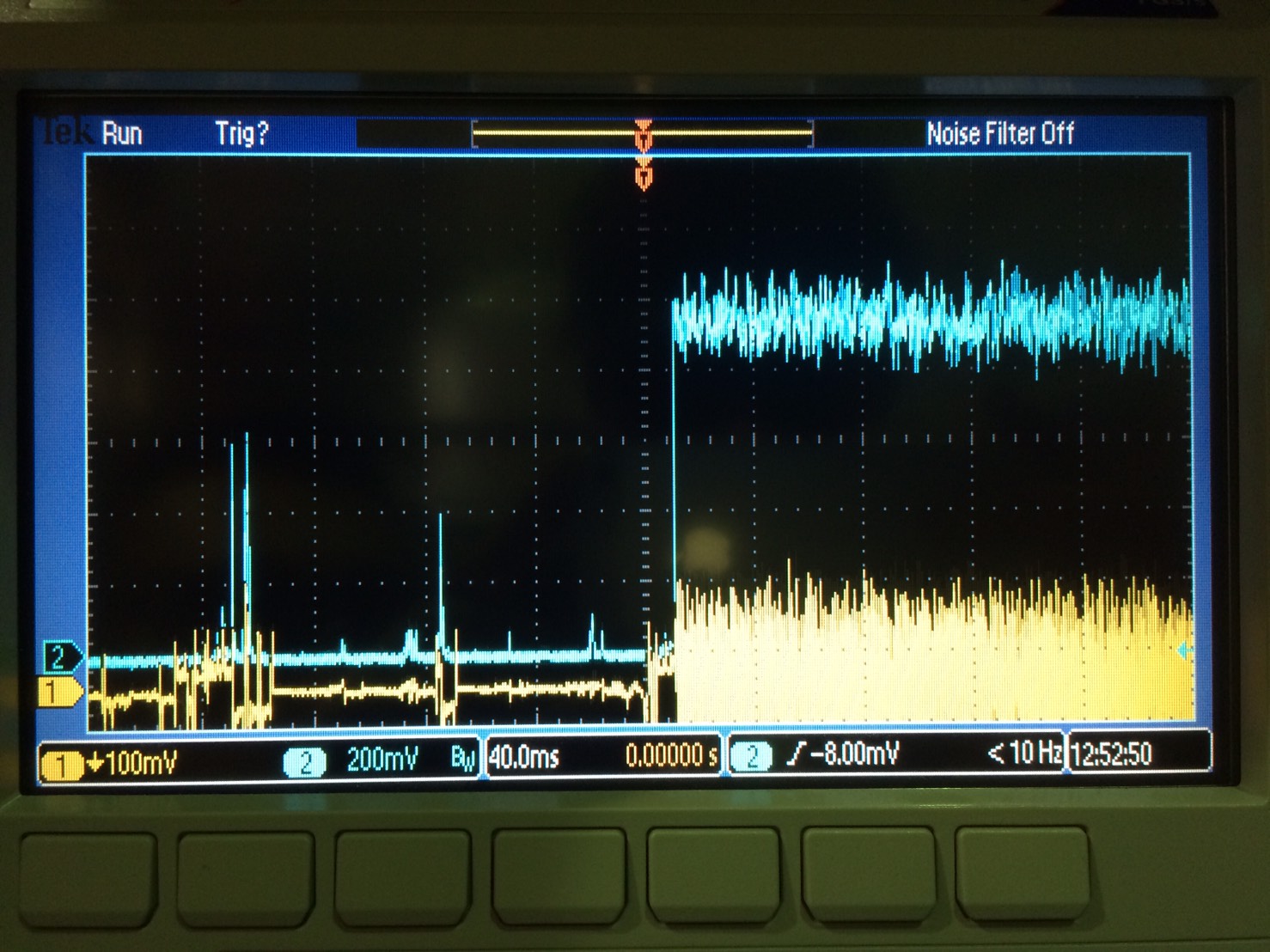
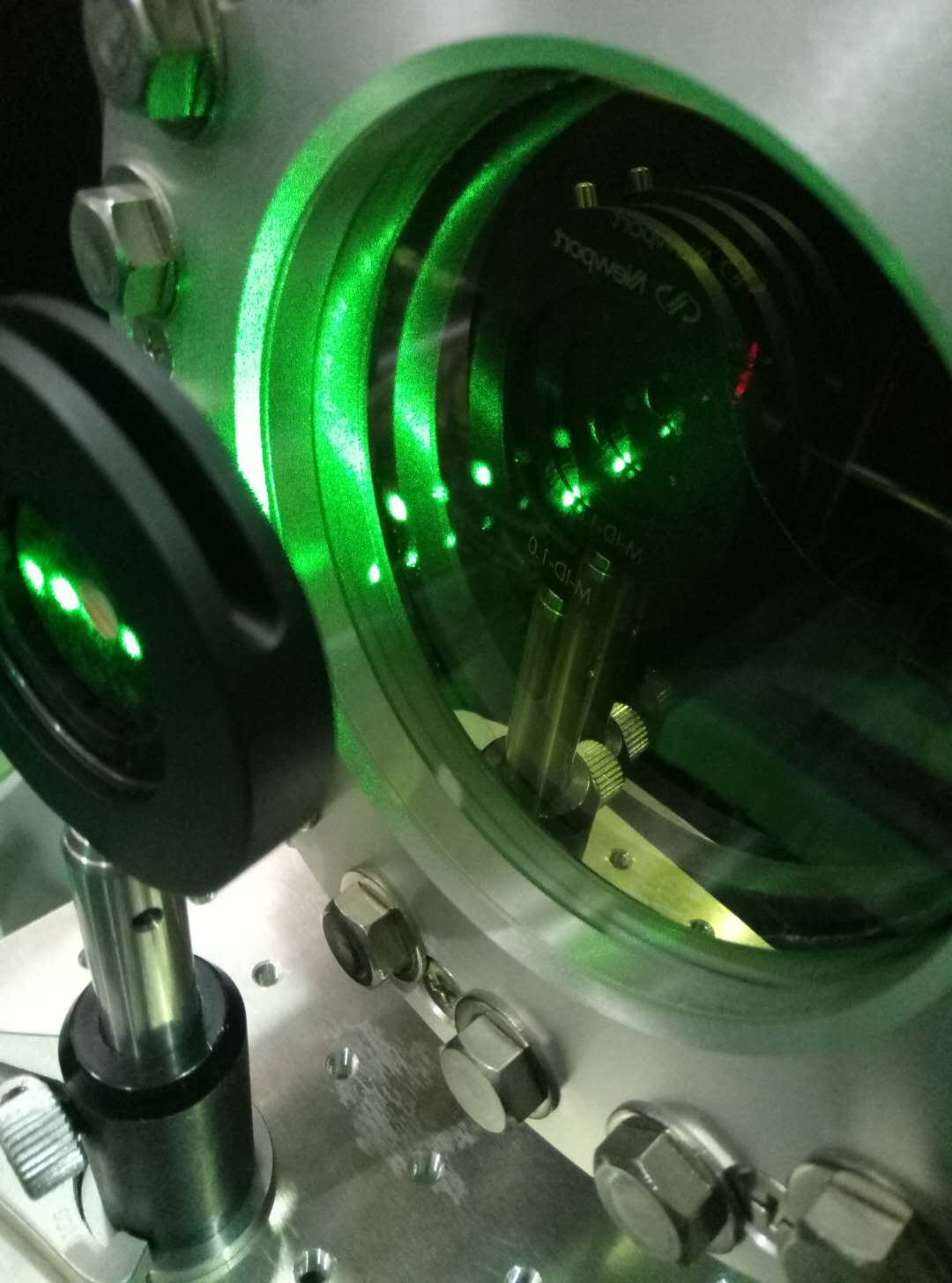
4.Before this week's locking, I found there is also drift. But it happened while the local control is off(see attached photo). And it is really similar with the photo I tool last time. I will check after this weekend where the beam will be next week.
We made a drawing of the clean booth in Tama, in orange lines.
I addition to the current clean booths, we drew a clean boot 2000x3000mm on the squeezing table and a 2000x2000mm on the PR tank.
We can see from the figure attached that DDS has something like a low pass filter inside.
I didn't know the drift problem before. I took the picture at laser injection window of PR chamber. You can see from Fig.1 the drift after around 12 hours. I remember that it will not happen when the local control is off.
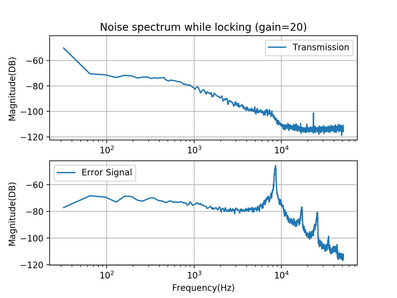
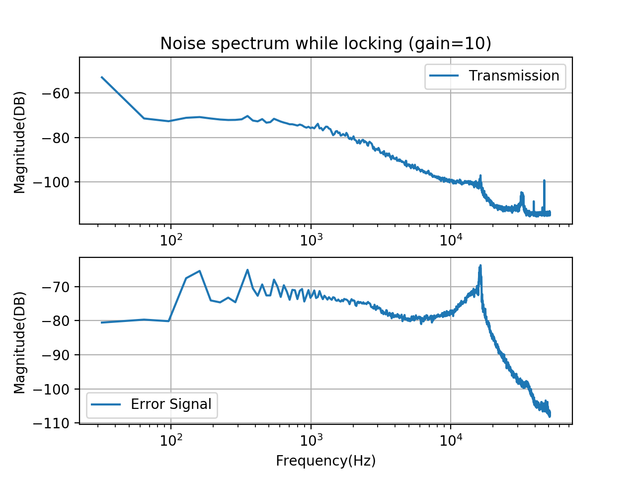
After fixing them, we still cannot fix the problem. We discussed this during the meeting and Eleonora suggested to decrease the gain. So I decreased it from 100 to 20. This is really effective. We can easily lock the cavity then.
But the problem is the locking of TEM00 is not very good. For transmitted signal, we can see from the oscilloscope that the peak is around 1.2V. But after locking, the transmitted signal can be only 0.4V in the best case. Besides, we can lock with higher-order modes and they have almost the same level with TEM00. This should come from the bad alignment. But I don't know how to make alignment better. It's really difficult to find a good way to improve this. We can see almost no change on screen the modes, on oscilloscope by changing the local control offset of mirrors.
We also measure the noise spectrum of transmitted signal and error signal with different gains. Please refer to Fig.2 and Fig.3
Members: Yuhang and Tomura
On 09 December, we found that the end mirror of the filter cavity had relatively larger variation in its pitch motion. As refer to in elog 428, the normal angular variation for the end mirror pitch with the loop closed was 3-4 urad. However, values we found there were 6-7 urad. As for the other mirrors (PR, BS, and IM), these values seemd decent or even better. We suppose this pitch noise on the end mirror can be one reason why we cannot lock the cavity although the beam seems to be well aligned. The reason of the noise itself is still unknown.
Takahashi-san showed us how to switch off the facility. Basically the vacuum system and the air compressor.
For each experiment, people working in tama must take care if turning off the instrumentation correctly.
Members: Akihiro T., Matteo L. and Yuhang W.
Some remarks about the filter cavity locking
On 07 December, we tried to lock the filter cavity at first, and then we found some problems.
When we switched on the loop, the yaw of IM mirror went to auto-oscillation.
Trying to figure out where the problem came from, we measured the meachanical transfer function and the open loop transfer function of each mirror (pictures to be posted later, sorry).
As a result, the MTF and OLTF measured had similar form. We consulted Eleonora for this problem and she advised us that it was possible that the loop filters were not applied on the LABVIEW program which we usually use. This was because the PC was wrongly shutted down the other day. When the PC is shutted down, a program which offers us the loop filters is also shutted down. In this case, one need to boot all programs again correctly. Finally, after applying the loop filters, the whole system (the filter cavity) seemed decent.
In the case of re-booting the PC, please boot the LABVIEW programs used to manipulate yaw and pitch of each mirror,and also a program named "my_Filter_Bank.vi" and load a file "filtrotot.txt" in it.
AOM miss-alignment
We also found that the first order diffraction of the green beam, which is inserted to the filter cavity, had less power. It is posssible that AOM is not alingned properly. We did rough measurement of beam power at some different points (shown below).
Right after SHG cavity: 57mW
Right after EOM: 49mW
After beam spriter before AOM: 9mW
Before iris in front of the chamber: 8mW
After the iris (the 1st order diffraction): 0.25mW
Members: Matteo L., Yu-hang Wu
On monday 6th of November several measurements has been performed. Here a list of the measurements and the results with some discussion.
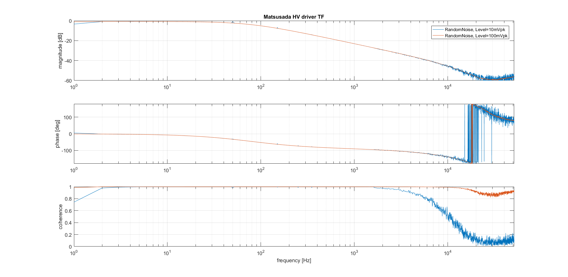
HV driver TF as function of the noise amplitude:
To understand if the low pass filter present in the HV driver transfer function (logentry 582) comes from a bad slew rate of the HV internal op amp, few measurements of the TF as function of the noise amplitude has been performed. The result is presented in Fig.1. If we compare the two measurement presented with the one done previously we see that the pole of the LP filter is unchanged with respect of the noise amplitude and it is always at 77Hz. Therefore the bad slew rate of the op amp does not seem the source of the low pass filter.
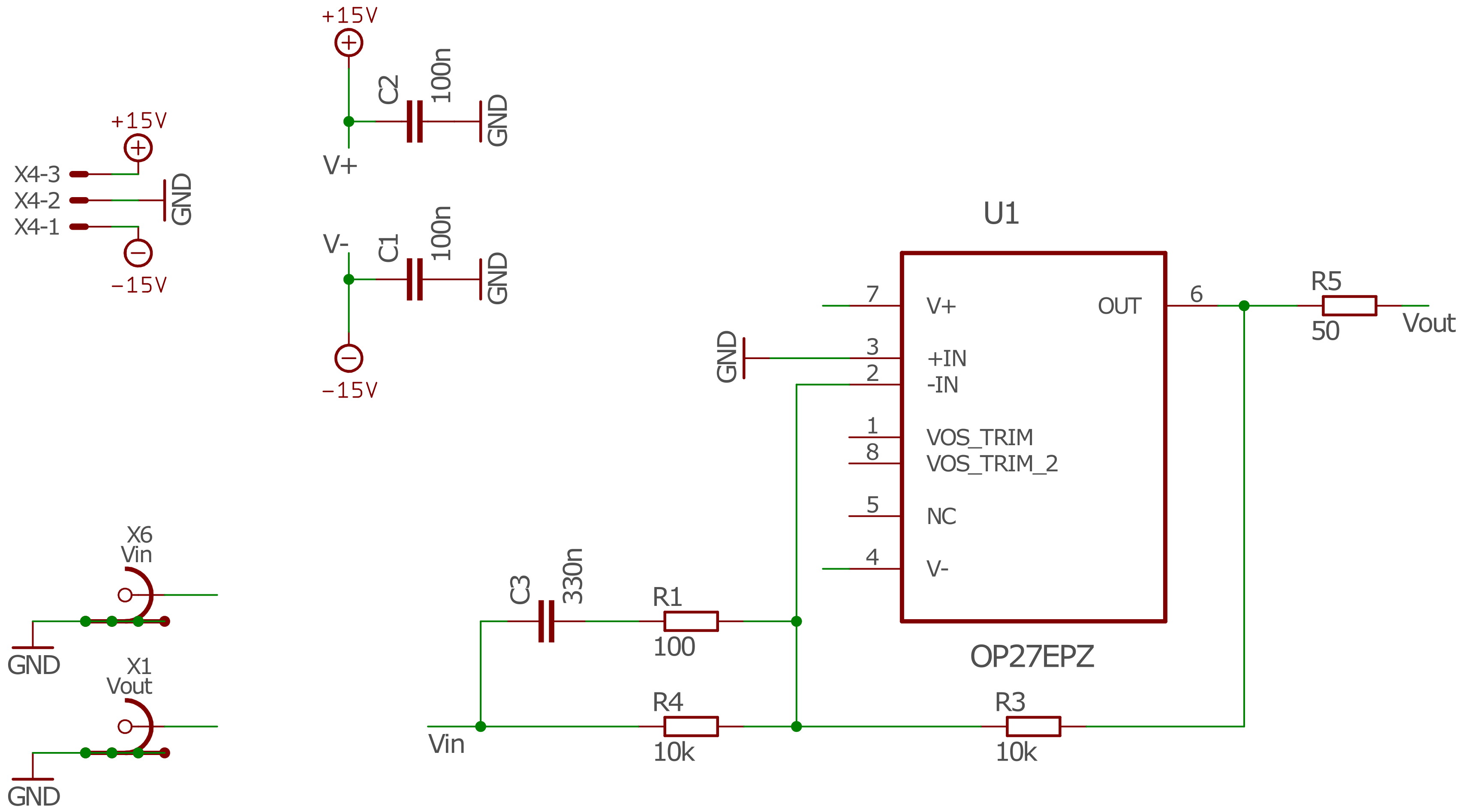
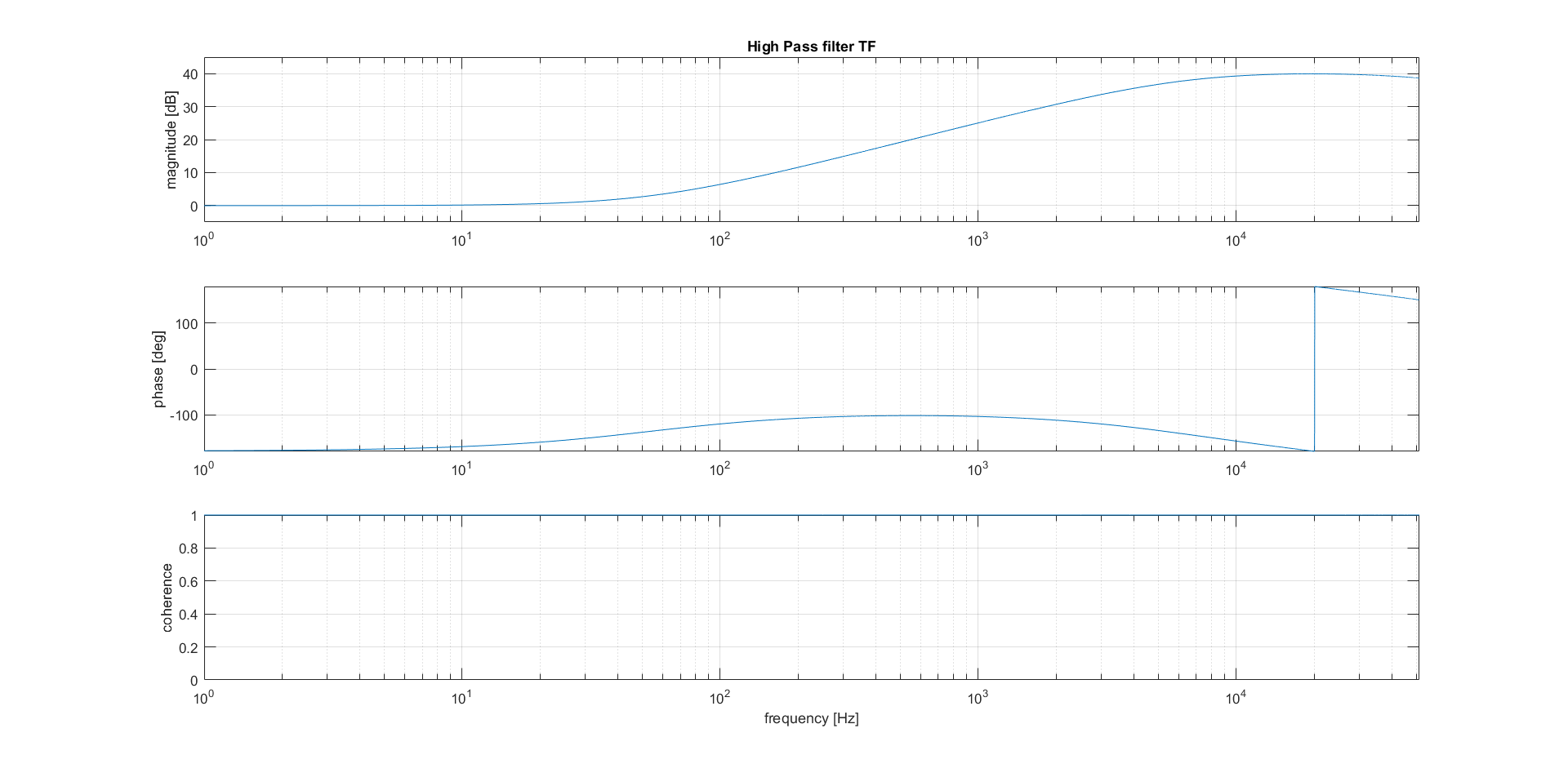
High pass filter and HPfilter+HVdriver characterization:
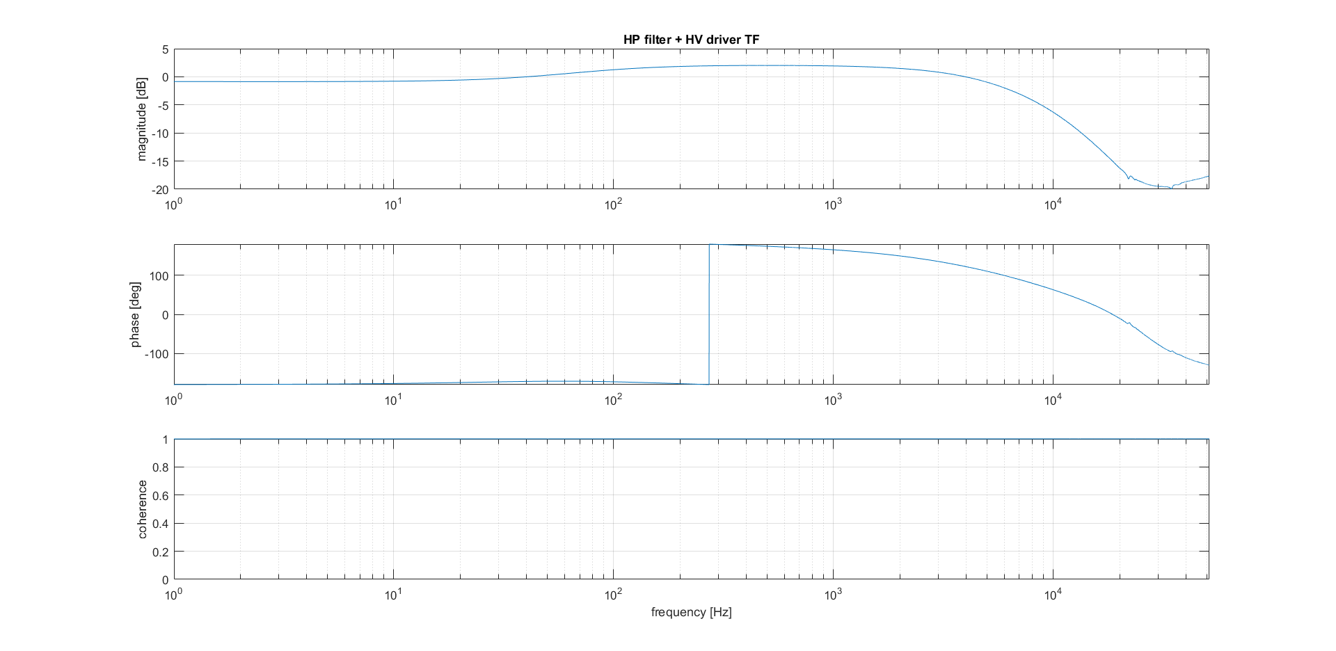
To try to remove the pole in the HV transfer function we added an active, first order high pass filter at the input of the HV driver. The schematic of the HP filter is presented in Fig.2 and Fig.3 shows its characterization. After inserting the HP filter at the input of the HV driver the transfer function of the system has been measured again and it's presented in Fig.4.
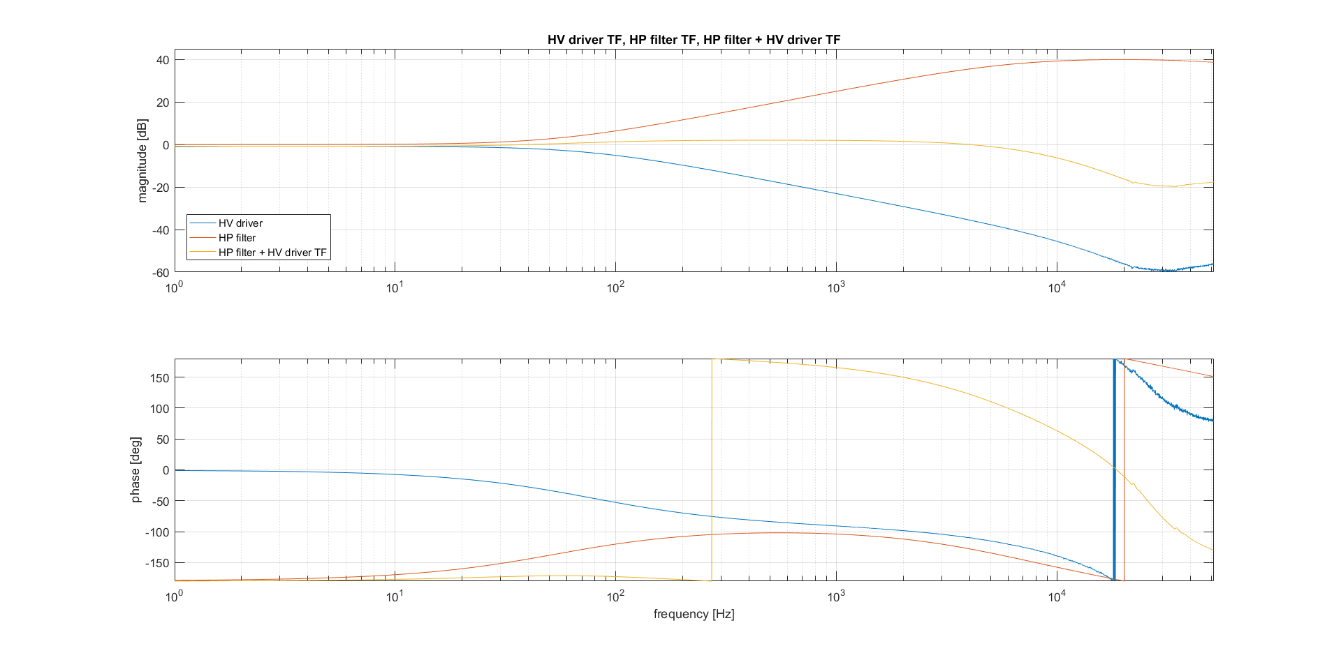
Fig.5 shows a recap of the HVdriver TF before and after adding the HPfilter.
SHG characterization after the modification of the HVdriver:
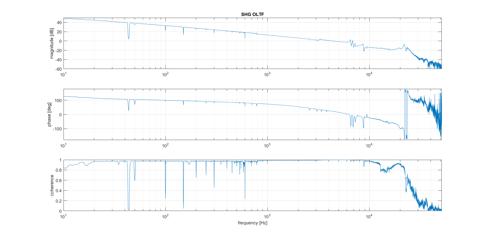
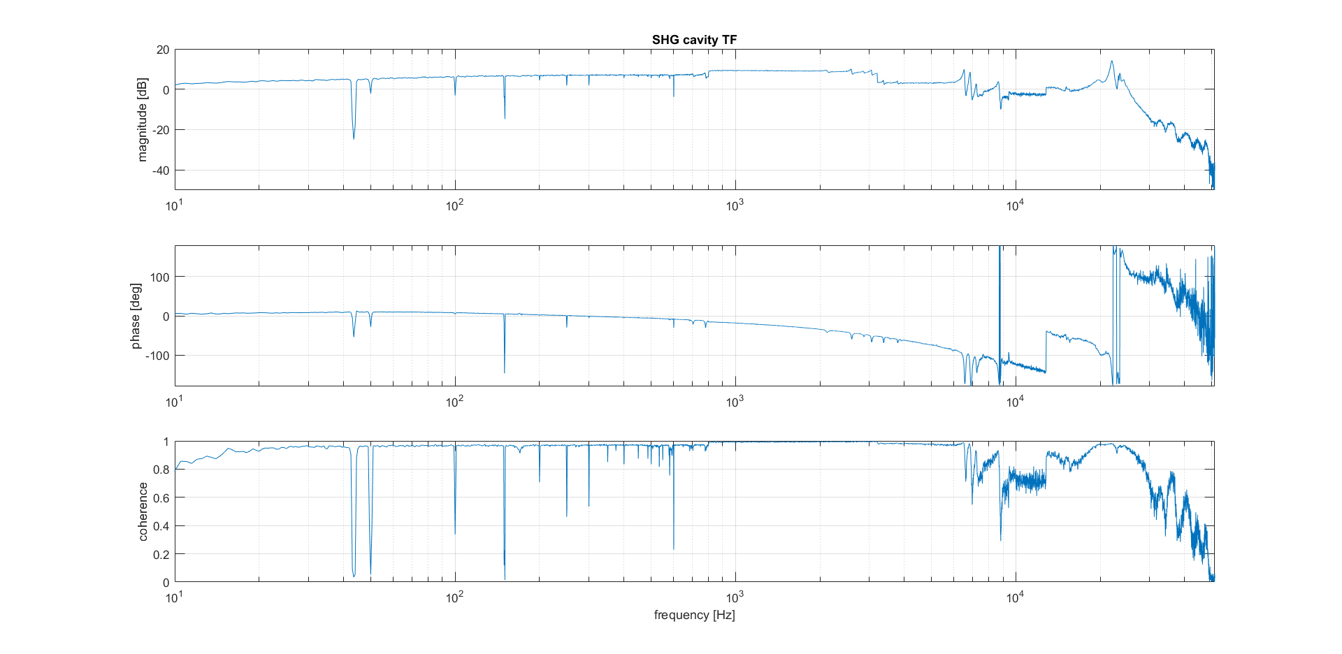
After adding the HPfilter the SHG's open loop and cavity TFs has been measured (Fig.6 and Fig.7). In order to have a stable loop the parameters of the servo (SR560) were changed: Gain=200 (before =1000), f3dB=10Hz (unchanged), invert=ON (before =OFF). Inverting the error signal was necessary due to the 180deg phase delay introduced at low freq by the HPfilter (the op amp is in inverting configuration).
All the TFs presented are pieced together from traces with different frequencies span. Only in the SHG cavity TF (Fig.7) there seems to be some problems going from one span to the subsequent. I don't think this issue is cause by any physical effect but further investigation will be performed.
As a result of adding the HPfilter to the loop chain the SHG cavity TF is reasonably flat below the PZT resonance and the unitary gain frequency of the loop has been increased from approx. 1kHz to approx.4.5kHz. In the next days we plan to play with the servo parameters to improve the unitary gain freq. and the loop stability.
Huge dT guess:
After the previous work, the time strip-chart of the produced green and the SHG IR transmission, as seen by two phodotiode, has been recorded (Fig.8). As it's clear the low freq fluctuation is still present. To better understand what is the dominant factor in this low freq noise the thermal control of the LiNb crystal has been swithed off and the two signals has been recorded again (Fig.9). In this situation (Tcrystal = Troom) the SHG cavity does not produce any green but the transmitted IR si much more stable, therefore we suspect that the crystal thermal control while operating at the phase matching temperature introduces a dT noise that the cavity lenght control is not able to compensate.
We plan to investigate in the next days on the thermal control in order to measure the temperature stability and to improve the temperature stabilization.