NAOJ GW Elog Logbook 3.2

Participants: Eleonora, Raffaele, Matteo L.
We have installed in the end bench a thorlab passband filter (FL1064-10) on the path of the IR beam after the harmonic beam splitter. This allowed us to get rid of the residual green light and finally to monitor the beaviour of the IR light when the cavity is locked.
By changing the driving frequency of the AOM installed on the green path we were able to induce a frequency shift between the the green and the IR frequency in order to have both resonant at the same time.
NOTE THAT: since the AOM is put on the green path, the change in the frequency which it induces is compensated by the servo with a change on the IR which is half of the frequency change in the AOM. This means that a shift of 1 MHz in the driving frequency of the AOM corresponds to a shift of 500 kHz in the frequency of the IR light.
In the following are reported some preliminary results that we were already able to obtain:
TEM00 resonance and FSR: The resonance frequency of the TEM00 has been found at about 109.366 MHz. (The standard driving frequency of the AOM is 110 MHz). We have verified that it occurs every time we shift the AOM frequency of 1 MHz, meaning that the FSR is 500 kHz, as expected.
Cavity finesse for IR: We did a rough estimatin of the IR linewidth by slightly changing the AOM frequency in order to scan the IR resonance. We drove the AOM in order to find the maximum in the transmission (about 1.5 V) and then we checked the frequency shift necessary to get half of the maximum. Repeating this procedure few times, we found a FWHM of about 110 Hz +/- 10. This corresponds to a finesse of about 4500 +/- 450, which is consistent with what we expect. The big error is due to a large fluctuation in the trasmitted power.
HOM resonance frequency: The first order modes have been found at a AOM frequency of 108.970 MHz (and FSR multiples). It means that the the difference in the resonance frequency betwen the fundamental and the first HOM is about 198 +/-1 kHz. This value is in very good agreement with what expected, considering the cavity g-factors computed by using the RoC values measured at LMA.
According to LMA measurement, we have R_in = 436.7 m and R_end = 445.1 m which correspond to a frequency shift given by
δν = (FSR/pi)* acos (sqrt (1-L/R_in)*(1-L/R_end) = 198.1 kHz
We also observed that different modes of the first order resonate at slightly different frequencies, which is likely to be an effect due to the astigmatism. More investigations have to be done.
Residual misalignment: by comparing the trasmitted power of the funtamental mode with that of the first HOM we estimated the misaligment to be between 20% and 25%.
Lock accuracy: Since we don't have an error signal for the IR lock, it is not easy to evaluate the lock accuracy. Anyway the fact that resoanance can be scanned by shifting the AOM frequency gives us a lower limit that is surely better than few tens of Hz, that is much better than the accuracy on the green lock, estimated to be about 100 Hz. This is compatible with the hypothesis proposed by Matteo B, according to which the IR pole (at much lower frequency than the green one) contributes to filter the high frequency laser noise, improving the lock accuracy.
Stability: Once put on resonace the IR seems to be stable as long as the lock is mantained, anyway we observed that when the cavity unlocks and relocks it is not always possible to get the IR resonant again. This is probably due to the fact that only half of the green locking points are also good locking points for the IR.
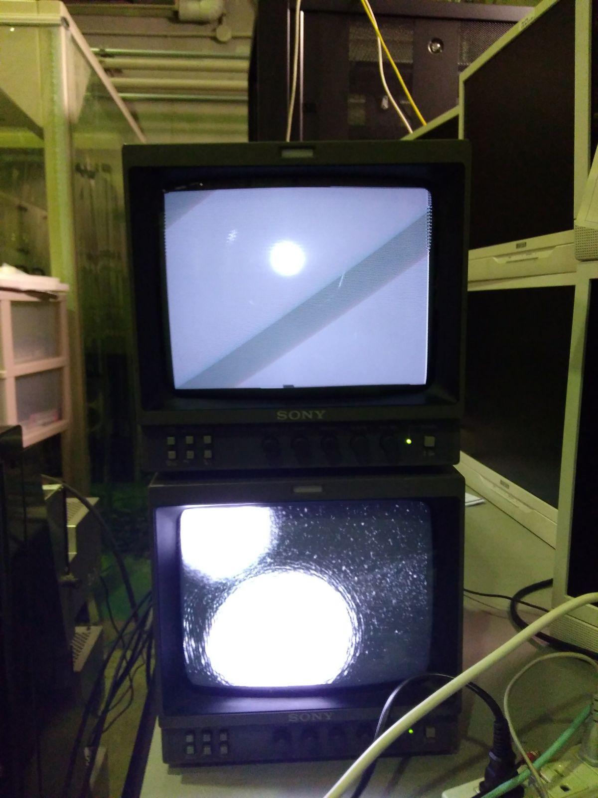
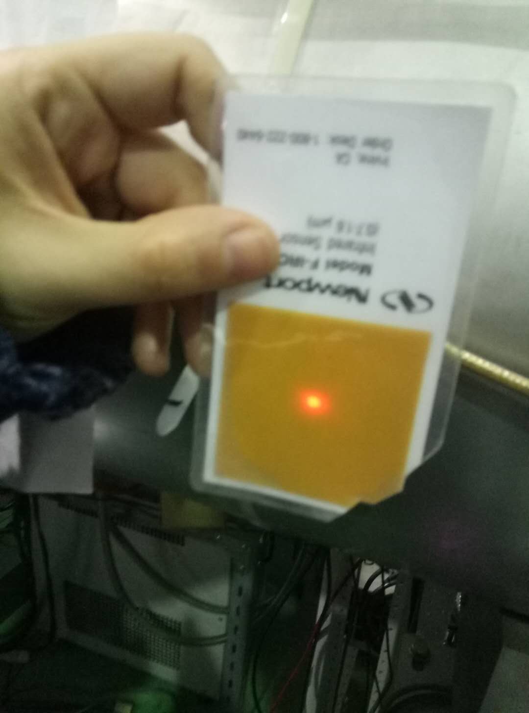
The attached picture shows the transmitted beam at resonance for the IR (top screen) and green (bottom screen)
Great!
Participants: Eleonora, Matteo L.
Last Thurday, while measuring the hight of some optical component on the bench, the green beam got a bit misaligned. When we realigned it, we observed that the trasmission when the cavity is locked is higher than usualy (1.5 V). The beam seemed still centered on the cavity mirrors and the IR is still well aligned.
We observed that the references of the PR and in particualr BS have slightly changed in yaw and we marked a new one.
At some point we had a problem of spikes with PR yaw error signal. We observed that this was the only one very far from zero. The spikes disappear as soon as we put it backto zero.
Participants: Tomura, Eleonora
As reported in entry 654, we had to move the yaw of SM2 dicroic mirror in PR chamber to avoid the IR reflection to touch the viewport side. Since after the last 1000 steps done, we were not able to get a good IR alignent anymore, yesterday we moved back SM2, hoping to find a good postion where we could have both a good alignement and the maximum of the power in reflection.
The input power is about 16 mW.
The situation is such that in the original position (before last thurday) the aligment can be very good but the beam hits the viewport side and the reflected power is very low (less than 1 mW). In order to have the maximum reflected power possible (about 12.5 mW) SM2 has to be moved so much and it is not possibile to recover a good alignent. (We remarked that in this case the cavity seems very mismatched, but we where not able to improve the situation by moving the last IR lens on the bench).
Today we tried to put back SM2 towards the original position and to fine-tune its position in order to have the best compromise between good alignement and high reflected power.
We did the followoing series of steps (velocity 500)
-300, -300, -300, -1000, -1000, -1000, +1000, +1000, +500, +300, -300, -300, +200, -100
In the end, we stopped in a position where we can have quite a good alignement (but not the best possible) and about 11 mW of reflected power. By looking with the camera it is not evident that the reflection is touching the viewport side.
We also moved the last IR lens back, from 20 mm to 17 mm.
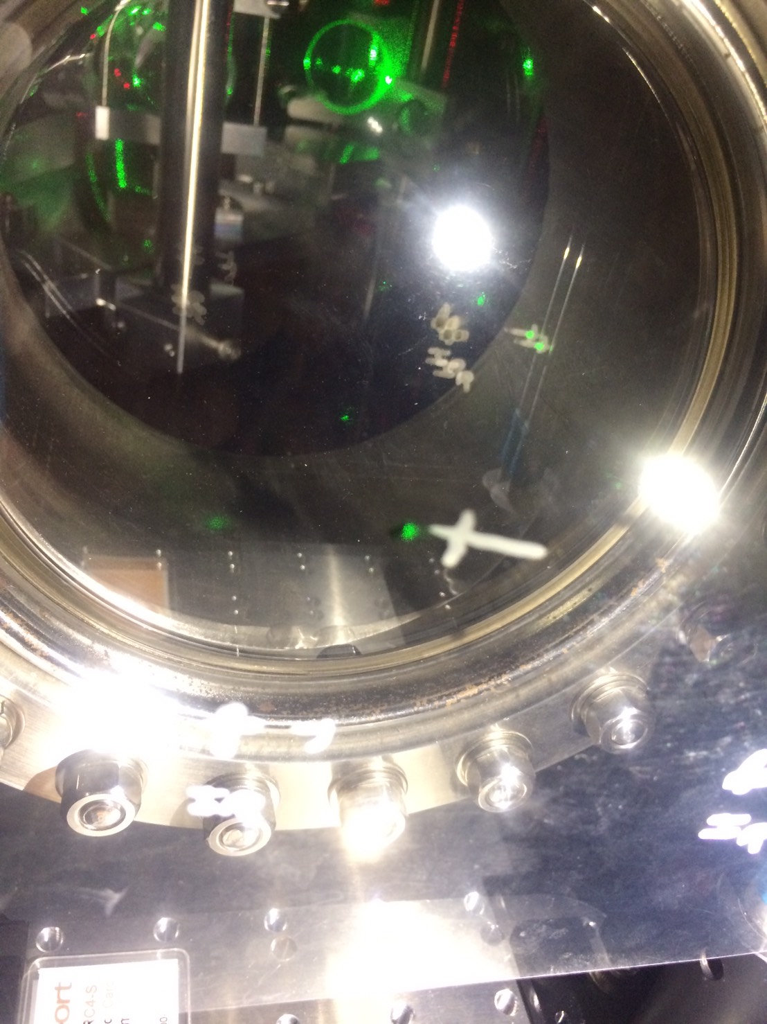
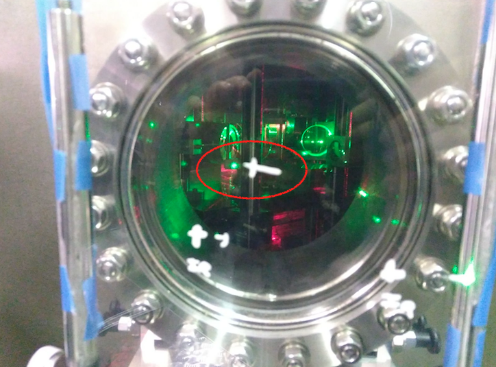
In the attached files we recoreded the new reference for the green beam: the white cross corresponds to the orginal position and the black point corresponds to the maximum displacement done by SM2.
Considering the maximum reflection we could get (12.5 mW over 16 mW), we estimated the injection losses in vacuum to be about 22% (11% single pass) which is not much higher than we expected.

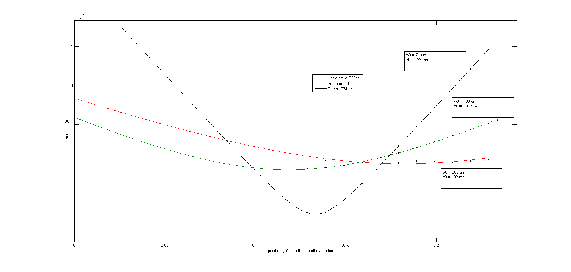
We measured the beam profiles of all the 3 lasers we have. See the plot
We aligned them at the cross point and maximized the signal using the surface reference sample.
Then we made a scan of the surface and the bulk reference samples.
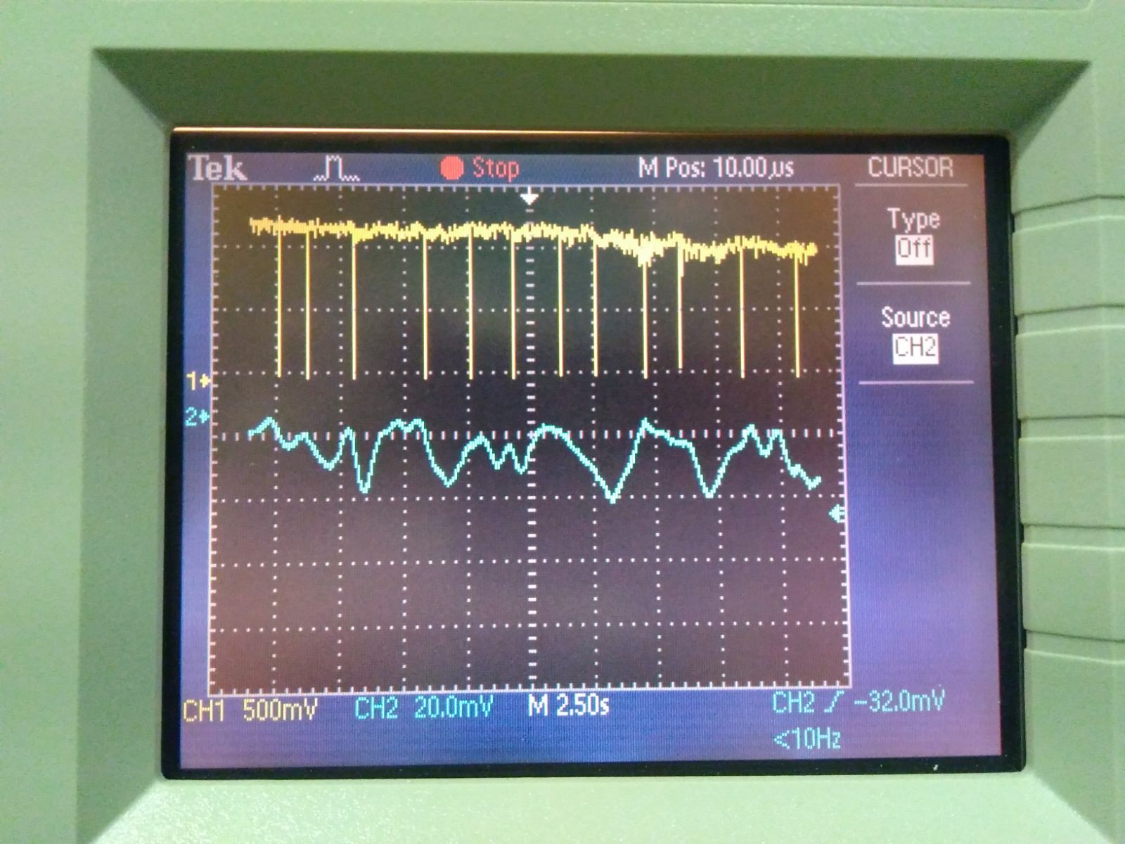
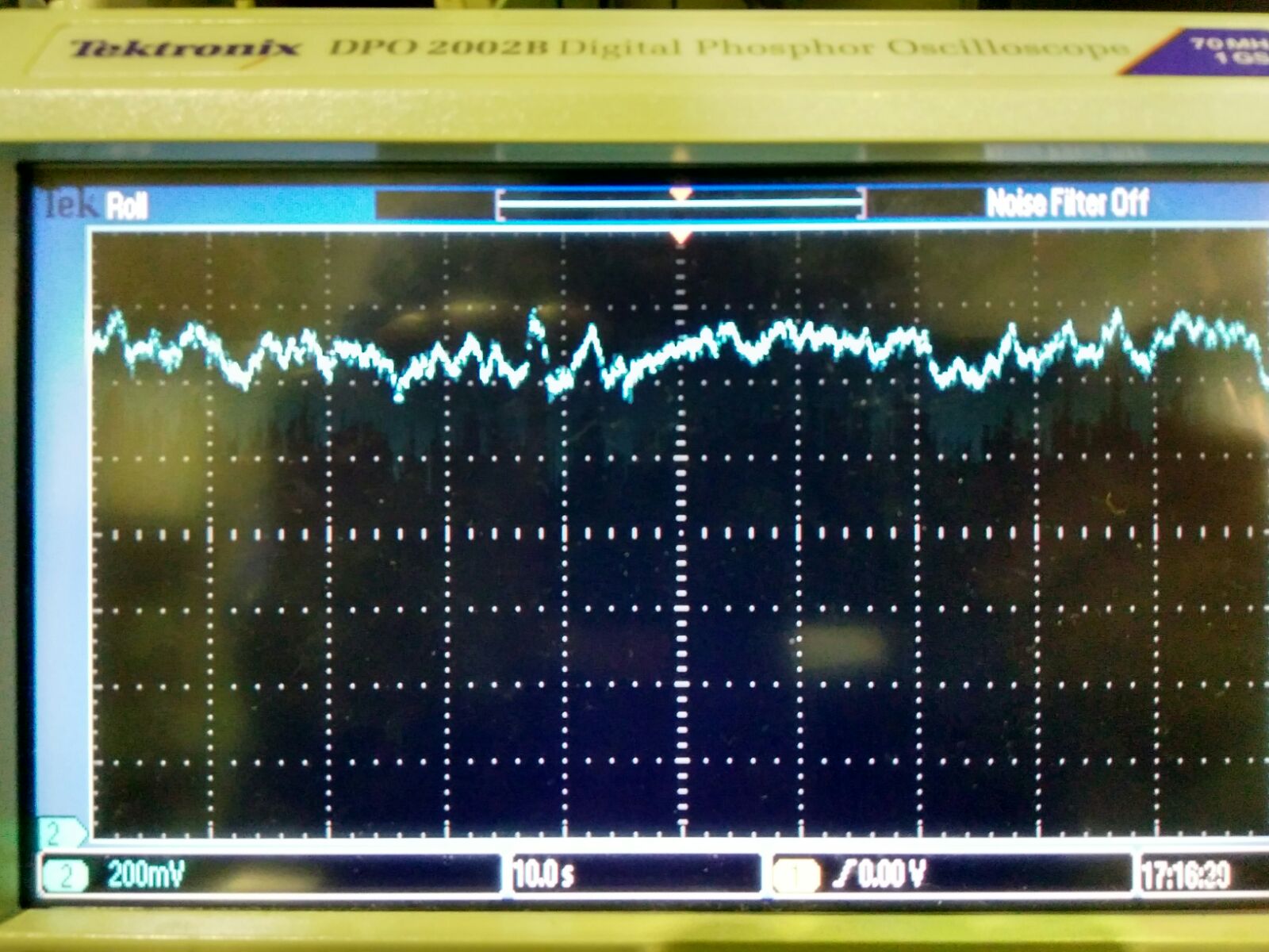
Yesterday I did a very preliminary check of the AOM operation. After locking the filter cavity I have changed the driving frequency of the AOM (which is normaly set at 110 MHZ) and I have looked at the correction sent from the servo to the laser piezo.
In the attached picture you can see in yellow the trasmission of the filter cavity and in blue the laser correction (from PZT mon).
I changed the AOM driving frequency in steps of 100 kHz each time. Most of the time this change causes a very short unlock of the cavity, as it can be seen from the picture. Nothing can be noticed in the correction signal.
Since the piezo calibration is 2 MHz/V and the channel PZTmon has an attenuation of 100, a change of 100 kHz should result in a change of 2 mV in the correction, which is likely not visible. I tried to do bigger steps but the cavity loses easly the lock.
I observed that the correction is about a factor 3 bigger than that measured this summer. (See last picture of entry 475)
Participants: Raffaele, Eleonora
As reported in entry 649, while improving the IR aligment we realized that the power of the reflected beam was very small. After some investigations we were able to see with the IR camera that the reflected beam was hitting a side of the inner part of the viewport. in order to avoid this we decide to slightly change the positon of the diachroic mirror SM2 (where green and IR recombine) in order to change the way the beam passes through the faraday.
We moved the yaw picomotor of SM2 several times (velocity 500, direction +), trying to recover the IR aligment with the two steering mirrors on the bench after each picomotor movement.
We did the following series of steps:
10, 10, 100, 300, 300, 600, 600 (Thursday) and 600,1000 (Friday)
Before the last movement (1000 steps) we were able to have a quite good alignment and a reflection between 11 and 12 mW (the input was about 16 mW), nevertheless we were still able to see some IR scattered light inside the viewport. After the last movement (1000 steps) the scatterd light was no more there but we were not able to recover a good aligment.
Sometimes, while recovering the aligment we had the impression that the matching was worsened (more LG modes), so we have changed the postion of the last IR lens different times in a range from 7 mm (original postion) to 22 mm.
Note that since we moved SM2, one of the two green references (the reflection from SM2) has changed accordingly. See attached picture.
Participants: Manuel, Eleonora, Tomura
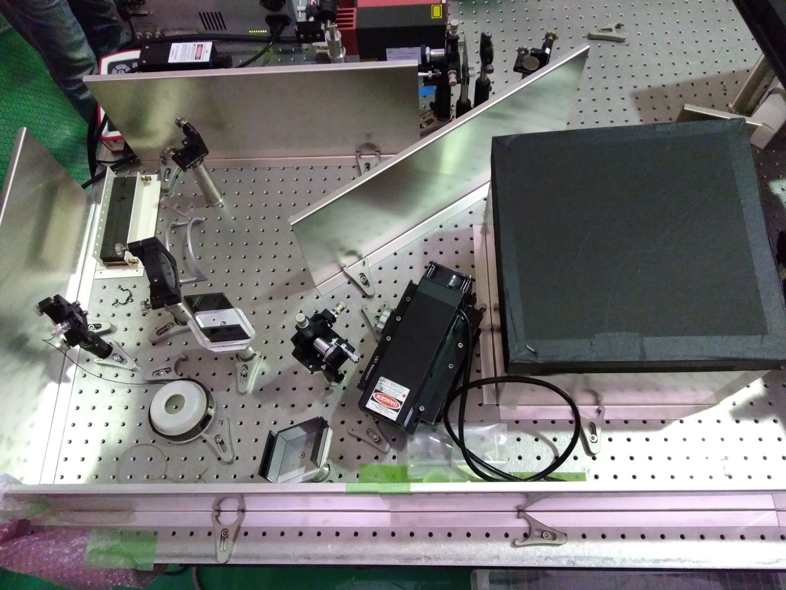
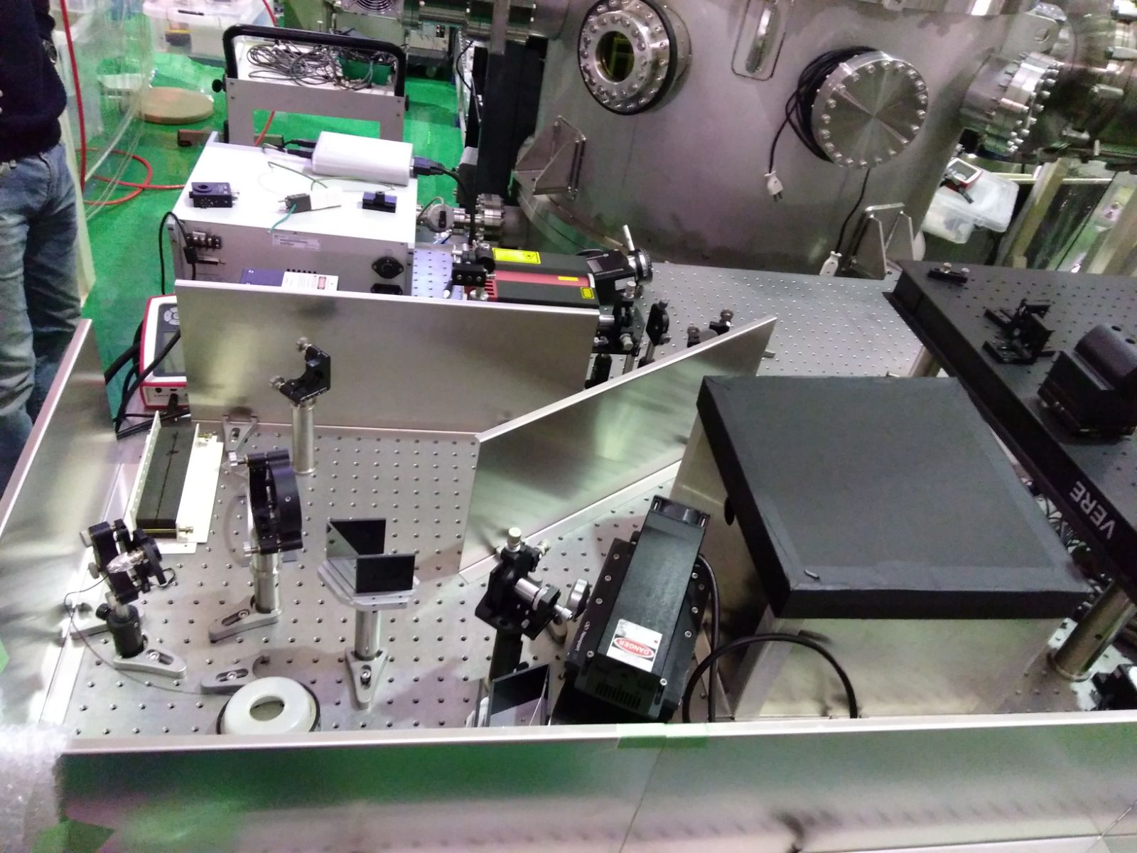
Today, after asking Takahashi-san, we removed most of the optics intalled on the optical table placed at the bottom of the stairs in TAMA central building. There were three lasers ( two 532 and one 1064) and many other optics which have been temporarily stored in a plastic box below the table. Currenty the table is being used to test the two auxiliary lasers and faraday isolators for the filter cavity experiment.
I attach some pictures taken to the table before we removed the optics.
Participants: Yuhang, Tomura, Eleonora
Today we kept working on the alignemet of the infrared beam:
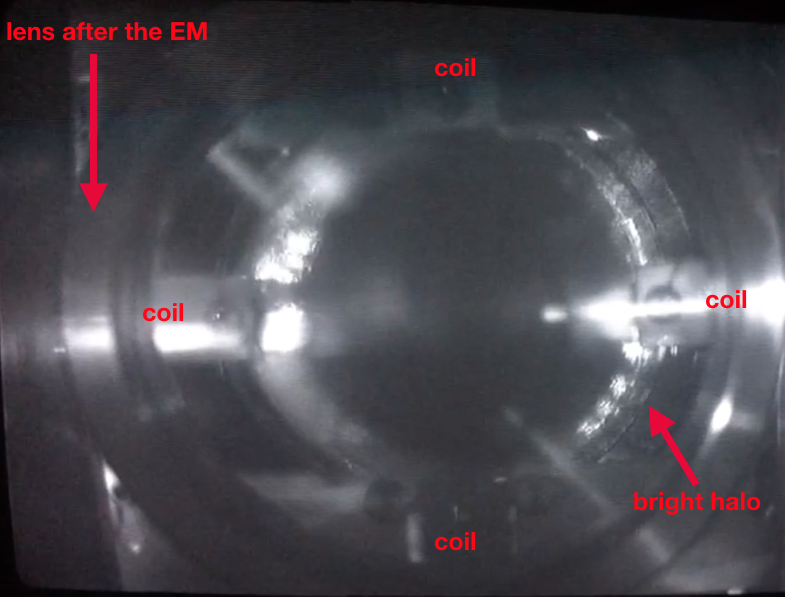
1) We have centered the green beam on the end mirror. To do this we have made a scan in pitch and yaw with the BS in order to reach the edge of the mirror and see the green beam on the coils. We recorded the corresponent offsets and pick the intereidiate value as the good one.
2) We have investigated the origin of the bright halo visible on the camera for the IR trasmission (see pic1). We have looked insiede the end bench putting a camera in the viewport behind the end mirror (the one through which the cavity transmission passes) (See picture 2). The bright halo seems to come from the contour of the end mirror. Raffaele suggested that it may be the light diffused by the input mirror at small angle, which is trasmitted by the most external part of the end mirror. In fact the HR coating has not bean applied there and it is almost trasparent. The fact that we see it very bright could be due to the comparison with the very small transmissivity (few ppm) of the HR coating anywhere else on the mirror surface.
3) We tried to maximize the alignement of the IR beam by moving the steering mirrors on the bench. As usualy it was done after having aligned the cavity for the green. We could obtain quite a good alignement but we observed that in this condition the reflection from the faraday was not maximized anymore and it became actually very small (less the 1 mW, with 16 mW in input). This suggest that the axis of the faraday is not well aligned with that of the cavity and so an additional work to align them will be required. To my knowledge we have never payed attention to the faraday reflection while aligning the IR beam in the past, so it is likey that it was the case also before.
The NTC used seems to be SEMITEC 103JT-050.
According to the datasheet, the R25 = 10kΩ ± 1% and B = 3435K ± 1% (note that this value is correct only between 25deg to 85deg Celsius).
PARTICIPANTS: Yuhang, Matteo, Raffaele, Tomura, Eleonora
Finally today we managed to realign the IR beam.
First we aligned and locked the cavity with the green light and then we cut the green.
We checked the IR reflection from the invacuum faraday on the bench and we maximized it by moving the two last steering mirrors for the IR on the bench.
The laser power is set to the standard value (current: 1.2 A), the incoming IR beam just before the windows is about 16 mW and the maximum reflection we could find is 12.8 mW. Increasing the laser power (2 A) we have an incoming beam of about 33 mW and the maximum reflection is about 25.7 mW
We checked that the reflection was moving accordingly to the IM motion, so we were pretty sure that it was coming back from it.
After maximizing the reflected power the beam was good on the PR reference but still we couldn't see anything on the first target, except for a very dim scattered light.
Then we put down the first target and rised the second target where we found a very strange beam, showing some fringes. We observed that fringes were reduced and the shape changed when we misaligned the end mirror.
After that, we reinstall the IR camera in the end bench and we center it by using the residual transmission of the green (when it was locked). By changing the yaw of the BS of a small amount we were able to see IR flashes on the camera. Then we put the BS back in the initial position (the one that makes the green to flash) and we adjust the yaw of the two last IR steering mirrors on the bench in order to make the IR flashes appear again. In this condition we have both green and IR aligned in the cavity.
The IR aligment was not optimized: we were still able to see HOM flashing but it is not easy to fine tune the alignment by moving the steering mirror on the bench
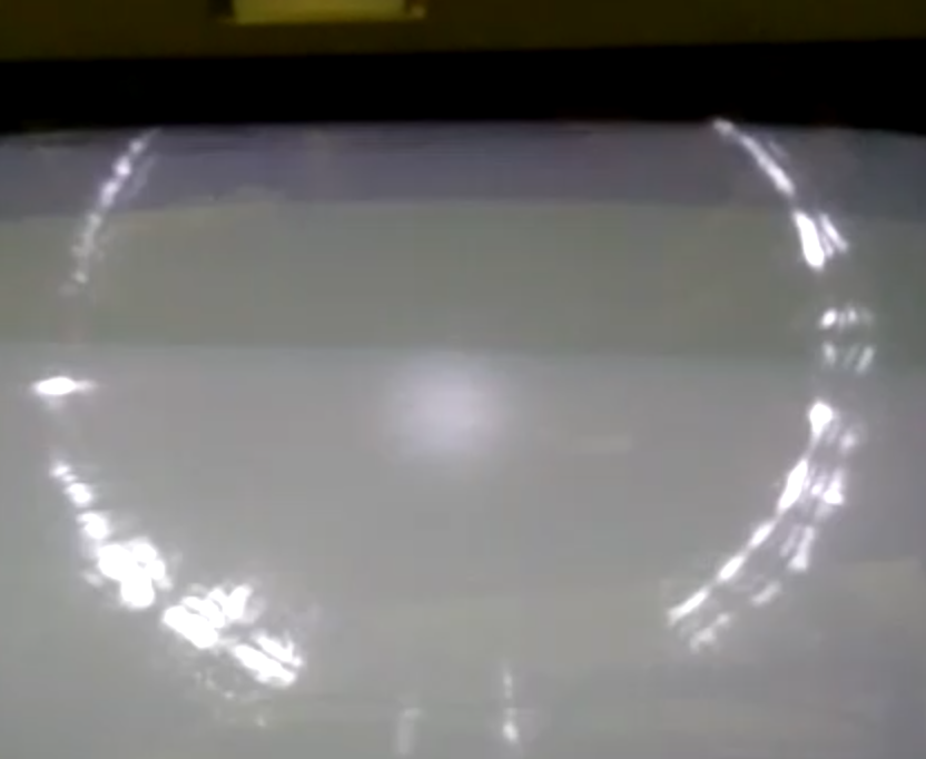
We remarked that there is a very bright circle of IR light on the end camera around the flashes. It resembles the contour of the end mirror and it is not clear why we can see it. Since we suspect a mismatching we tried to move a bit the last IR lens on the bench but it didn't improve the situation. (We put it back to the previouse position.)
Lessons learned:
1) The reflected beam is a good reference for the alignment of the beam and it should be maximized as a good starting point.
2) The behaviour of the IR beam on the target when it is aligned is much diffent from that of the green
- we can't see anything on the first target, so we should probably not consider it in the future
- when the second target is up proobably same unpredictable reflections between the mirrors and the target produce a very strange beam.
More work will be done to understand the origin of the bright circle and to improve the alignment.
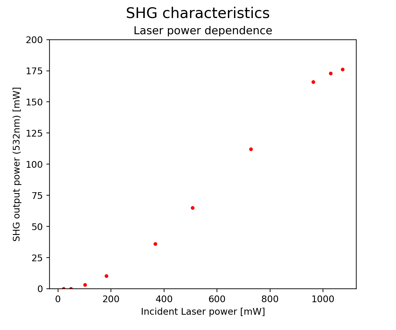
Thanks to thermistor data sheet from yuefan and the data tomura-san and I took(see e-log 627). I finished the SHG characterization work.
Since the data sheet doesn't give us a formula but only a few points, I use them to make a cubic interpolate. Then I use the interpolation data to make the plot so that you can see the relationship between crystal temperature and Laser power.
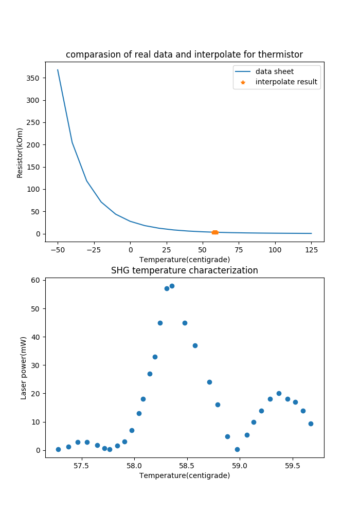
The NTC used seems to be SEMITEC 103JT-050.
According to the datasheet, the R25 = 10kΩ ± 1% and B = 3435K ± 1% (note that this value is correct only between 25deg to 85deg Celsius).
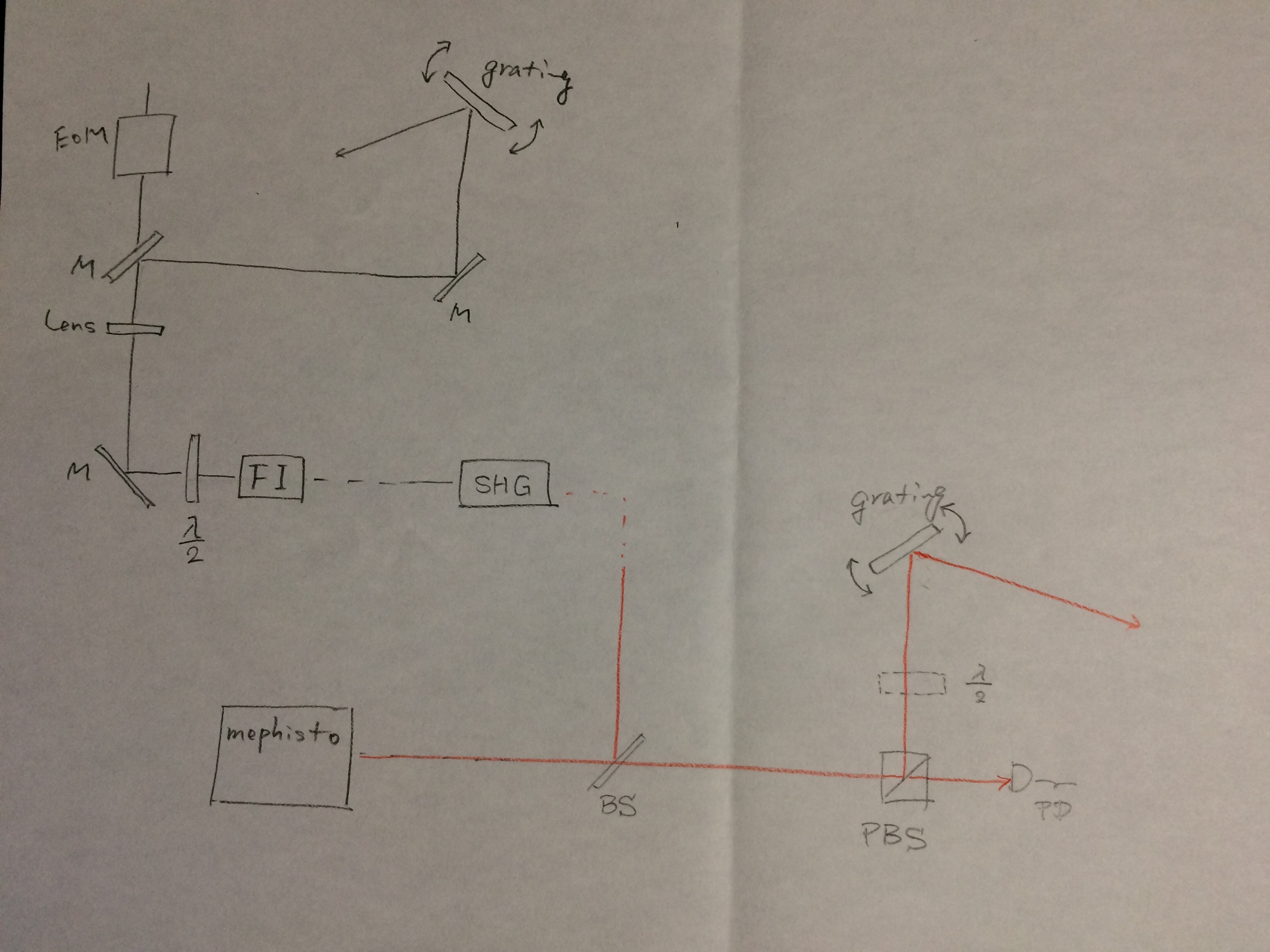
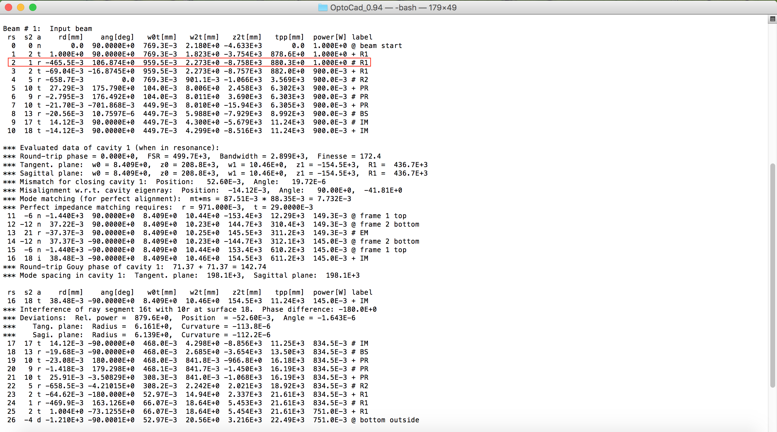
Today I finished the OptoCad simulation with practical scenario. I used the real measurement distance for optical components on the bench, and the in-vacuum distance from yuefan's e-log entry 441. I tried also to fine tune(means to move it with like two milimeters) the position of the last infrared lens on the bench. However, the results turn out to be similar with each other when you just look the simulation output picture. And also you can find the output data is similar. For example, the beam size around FI for them are 1.06mm and 1.36mm individualy. See attached file1~4.
However, we can see from the above attached simulation pdf file that the entering beam of PR chamber has some anomalous behaviours. You can see from attached file5, it shows only the incident beam and it is really good. That means bad thing is reflection. I also checked the output txt file and confirmed the anomalous comes from the reflection of cavity. However, since now I haven't found that why it is like this. I would like to talk with Matteo next week.


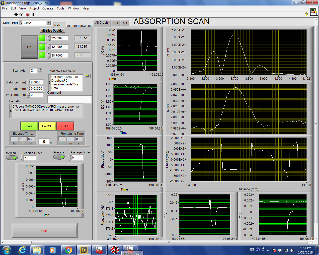
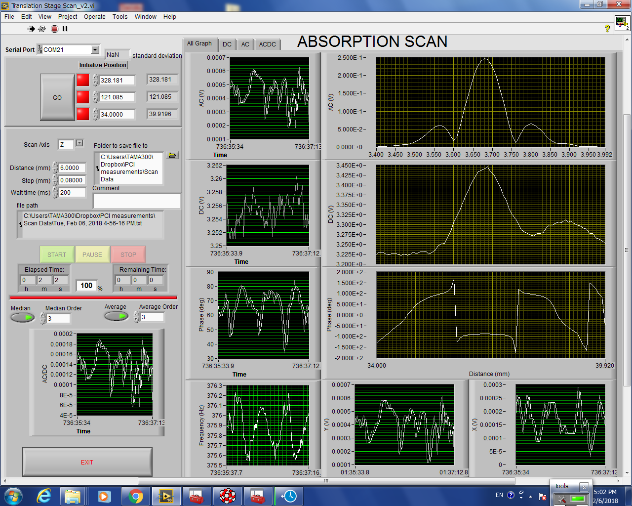
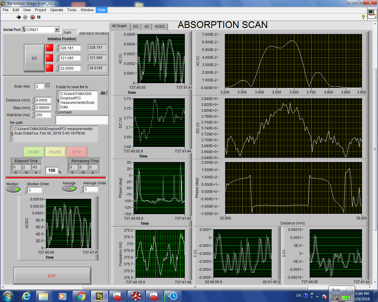
The usual procedure to align the beam for a best absorption signal is:
- to make the 2 beams pass through the pinhole
- maximize the DC centering the probe on the detector
- maximize the AC aligning the pump.
Adding the second probe beam makes things a bit more difficult because if we move the pump, we lose the alignment with the other probe. So, the maximization of the 1310nm probe AC signal have to be done without moving the pump.
Since the 1310nm probe turns out to be difficult, we decided to follow the usual procedure for the 1310nm laser, moving the pump to maximize it. Then try to recover the alignment on the red probe without moving the pump.
38.85mm is the position of the maximum of the scan with the red probe. Then we move the pump to find the maximum with the 1310nm probe.
filename:
Mon, Jan 22, 2018 3-01-33 PM.txt ; pd distance 83mm. Stage pos: 9mm
Mon, Jan 22, 2018 3-53-55 PM.txt ; pd distance 95mm (not better)
Mon, Jan 22, 2018 3-59-17 PM.txt ; pd distance 65mm
----------------------------------------------------------------------------------------------------------------------------------------------------------------------------------------------
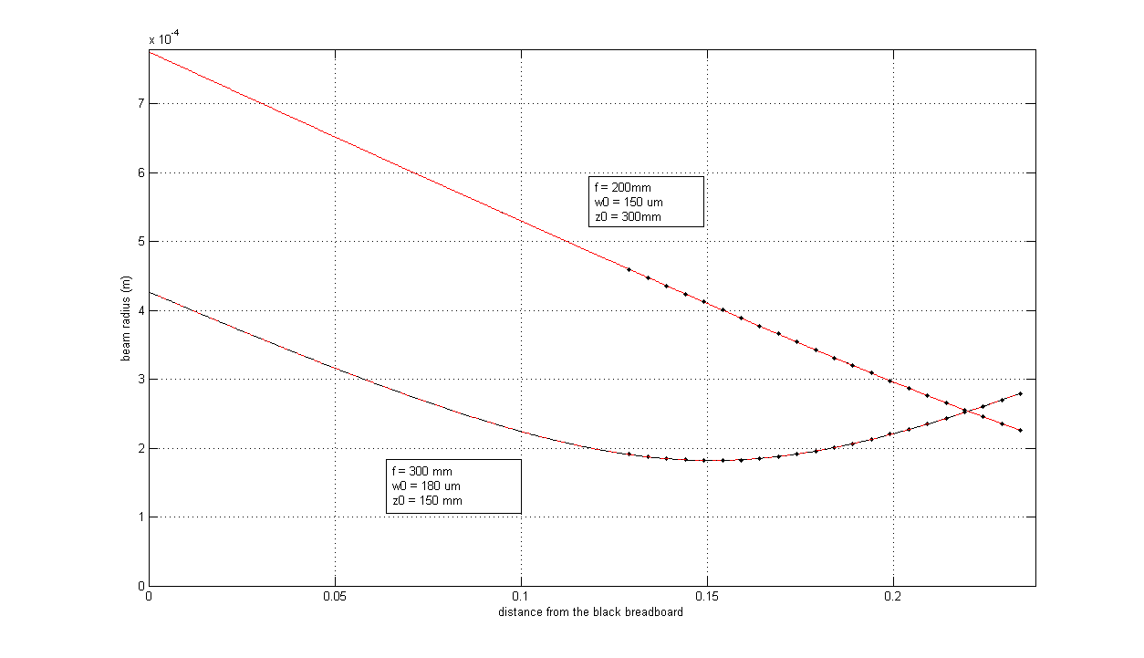
After trying the alignment many times, I noticed that the 1310nm probe is not focused properly, so we decided to measure the beam profile.
We discovered that the waist position is about 6 cm after the crossing point.
So we decided to change the focusing lens from f200mm to f300mm and to move the lens backward.
Yesterday we have worked on the characterization of the filter cavity lock.
First we have experienced some trouble with the labview ADC of the local control signals for the input mirros. The error signals for the pitch and the yaw looked the same. After some attempts the problem was solved simply by switching off and on the CPU unit. We have already observed this problem in the past but I could not understand what triggers this kind of behaviour.
After recovering the local control we could align and lock the cavity.
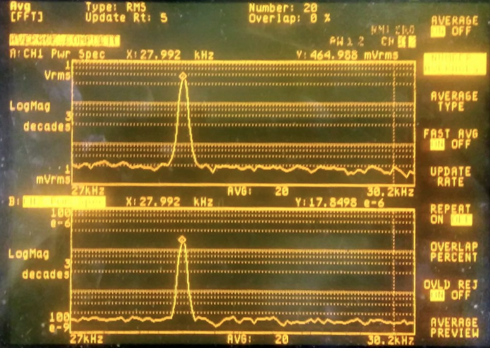
At first we wanted to measure the calibration factor for the error signal. In order to do that we summed a line to the piezo correction (input channel " RAMP") above the UGF.
We monitored the amplitude of the line on the monitor channel "PZT mon" finding a value of V_RMS = 17.84e-6 V.
The correspondent amplitude in Hz is
S_Hz = V_RMS (V) * 100 * sqrt(2) * 2e6 Hz/V = 5045 Hz (1)
The factor 100 is the attenuation of the "PZT mon" channel
The factor sqrt(2) is to pass from V_rms to the line amplitude
The factor 2e6 Hz/V is the gain of the piezo after the SHG
The correspondent amplitude observed in the error signal is
Err_V = K(V/Hz) * S_Hz/sqrt(1+ (f/f_0)^2) = sqrt(2)* 0.465 V (2)
% (2020/09/04) Note that this formula should be Err_V = K(V/Hz) * S_Hz/sqrt(1+ (f/f_0)^2)
Where we have taken into account the effect of the cavity pole assumed to be at f_0 = 1.45 kHz.
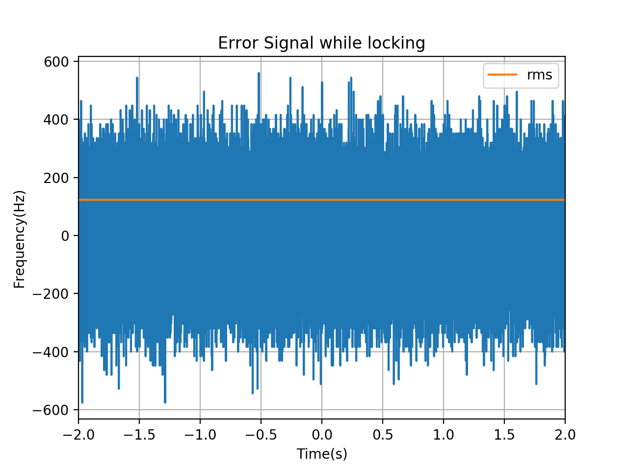
Comparing the amplitude of the two lines (see picture 1), inverting Eq. 2. We could find the calibration factor K (V/Hz) = 2.5 e-3
We have used it to calibrate the error signal into Hz and we obtain a lock accuracy of about 120 Hz, (see picure 2) which is similar to what we obtained in July.
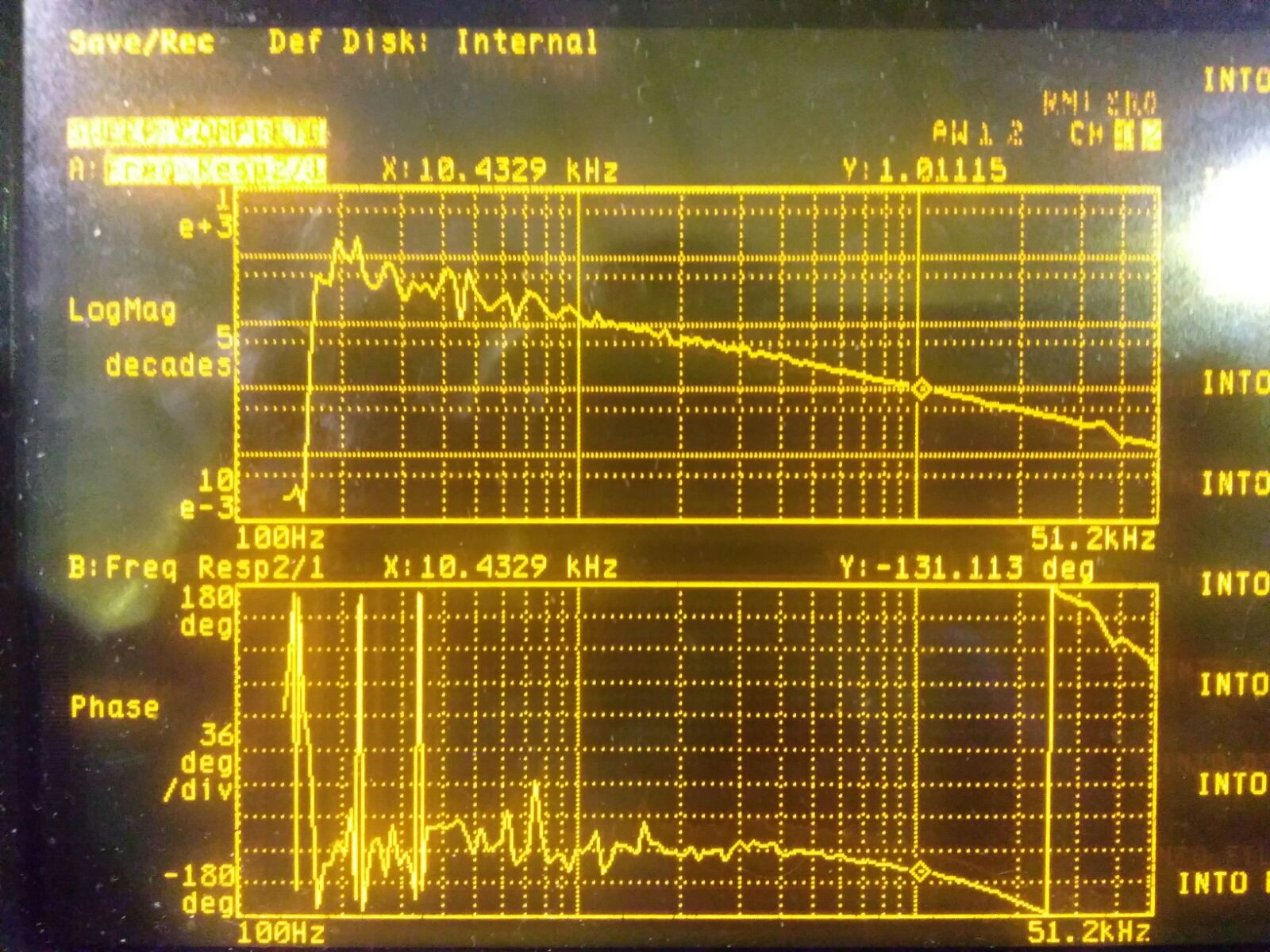
We have also performed a noise injection to measure the open loop TF finding a UGF at about 10 kHz with a phase margin of 50 deg. (See picture 3)
We have tried to change the gain but we observed that it was already optimized to have the error signal as small as possible.
In picure 4 the transmission of the filter cavity is plotted.
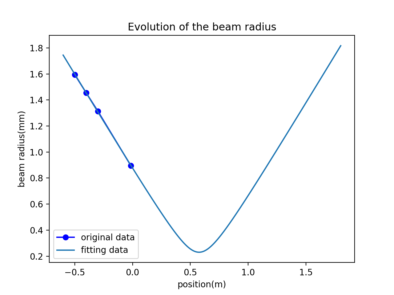
Since we found something wrong last week, we tried to carefully measure the beam parameters again after the first Faraday Isolator. As Yuefan did, we also set the origin as the BS on the bench.
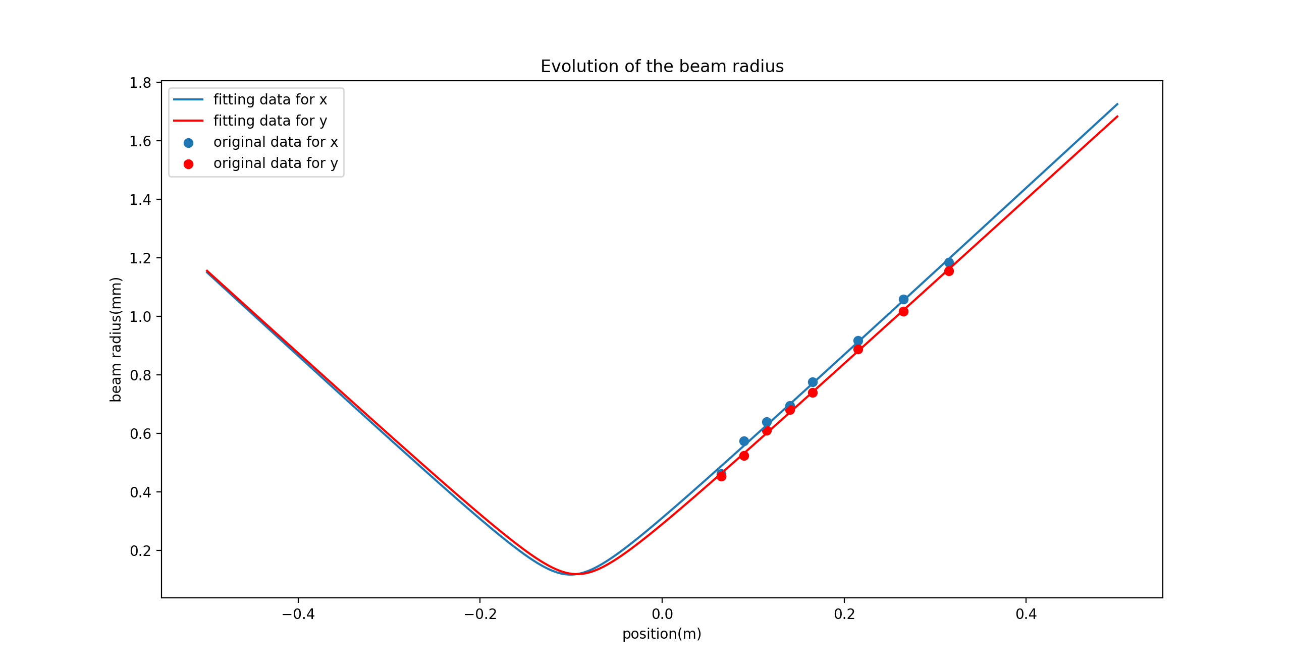
For x direction, the beam waist is 118.2 um at the position z=-0.10 m. For y, the beam waist is 119.8 um at z=-0.093 m. See attached figure 1 for the fitting result.
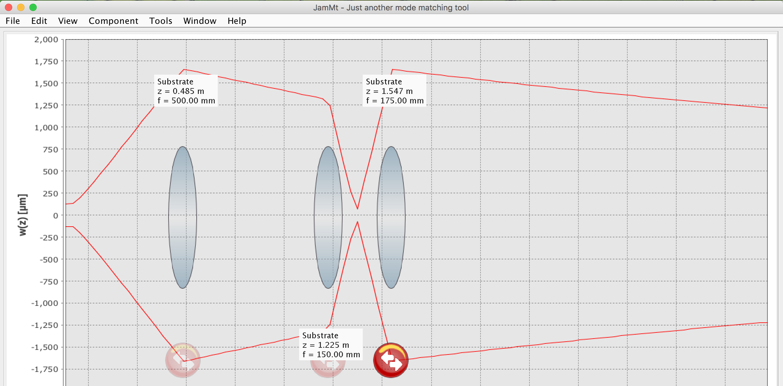
Then we used this result to simulate the propagation of the beam using the software "Jammt". See attached figure 2 for this simulation.
We found that our beam parameter was very sensitive to the last lens position. We have fine tuned its position in order to have a reasonable beam dimension. By using a steering mirror on the beam path we could propagate it for several meters in the central area and check that the beam size should be reasonable at the input of the in vacuum faraday.
After that we have keep trying to recover the alignment of the infrared without success. We have collected as many cameras and screens as possible as use them to look insides the input vacuum chamber simultaneously.
Despite many tries the situation is not different from that of the last time:
1) We can recover the references for the IR on the plastic film but for one of them the beam as a quite irregular shape.
2) We could see the beam on the mount of the 2 inch mirrors and we tried to center it.
3) We could see the beam hit the leg of the PR telescope mirror and tried to center it on the PR.
After that we cannot see the beam on the BS or on the input mirror but just some strange quite dim shape on the first target.
As already observed in entry 631, when moving the PR or BS mirror with the local controls we can move accordingly the shape on the target. This is different from what we expect if the beam was hitting the pipe, since normally in this condition we observe a change in the intensity and in the shape of the scattered light.
Conclusions: We are probably not understanding what is happening inside the chambers and we need some new ideas to go on.
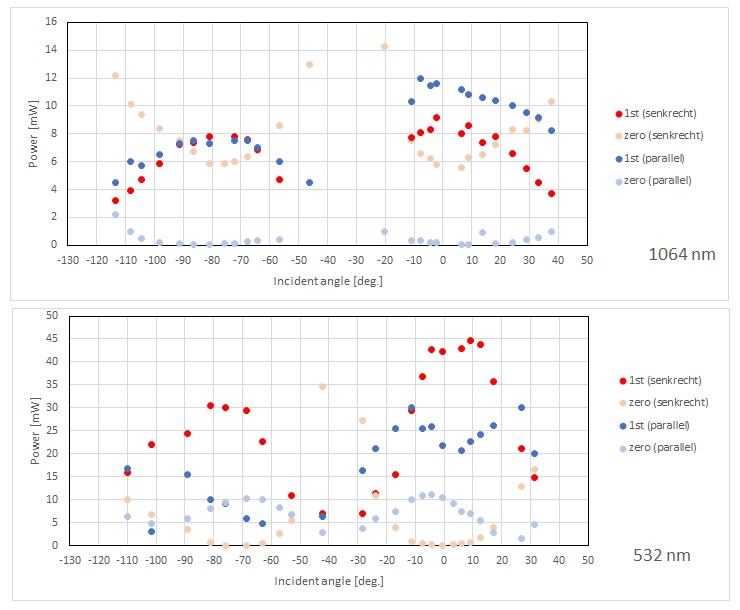
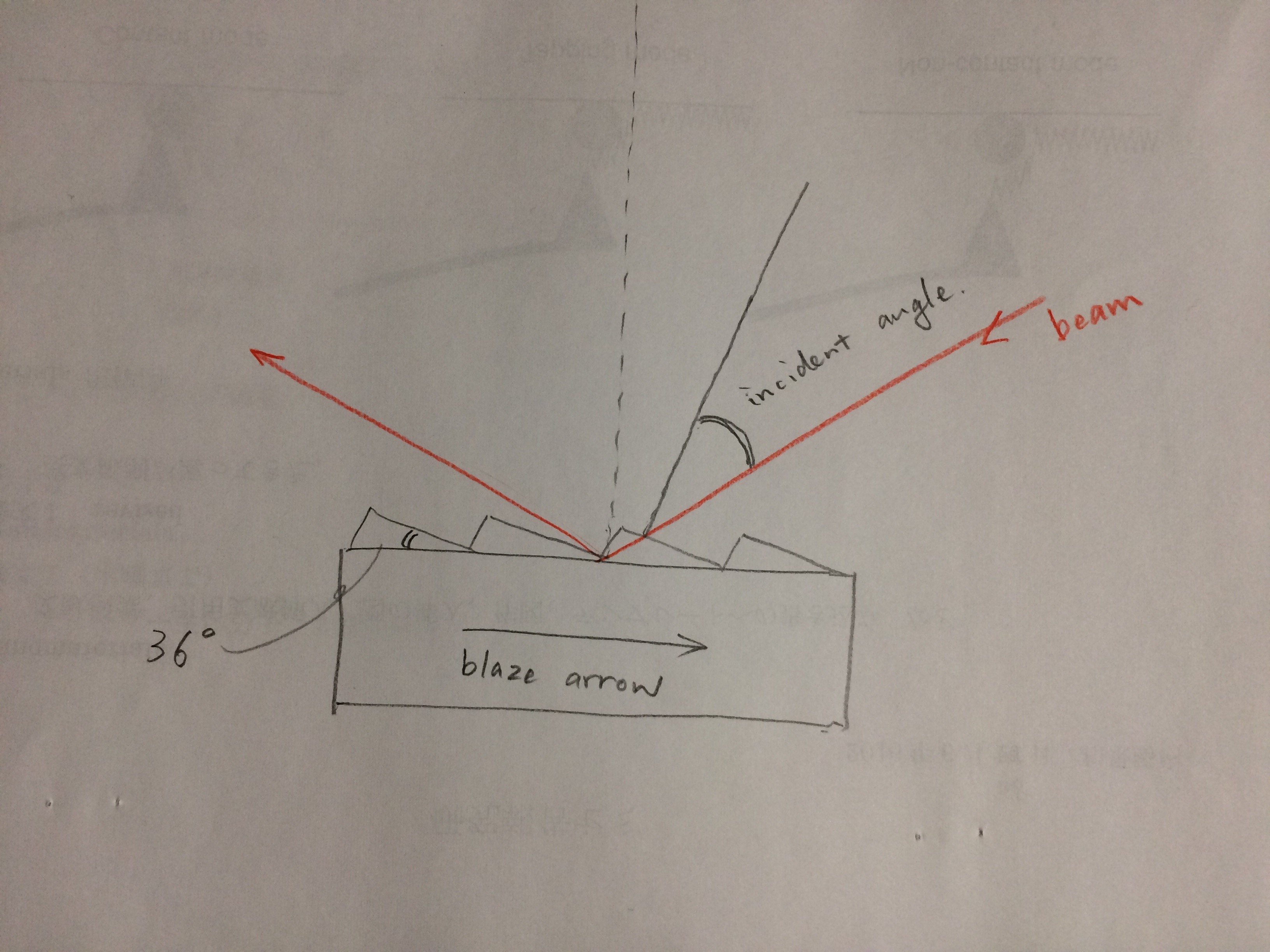
For the definition of the incident angle, please refer to figure 3.
For the spec of the grating, please refer to the attached pdf file.
I am not really sure about what I see on the graph.
I need your opinions.
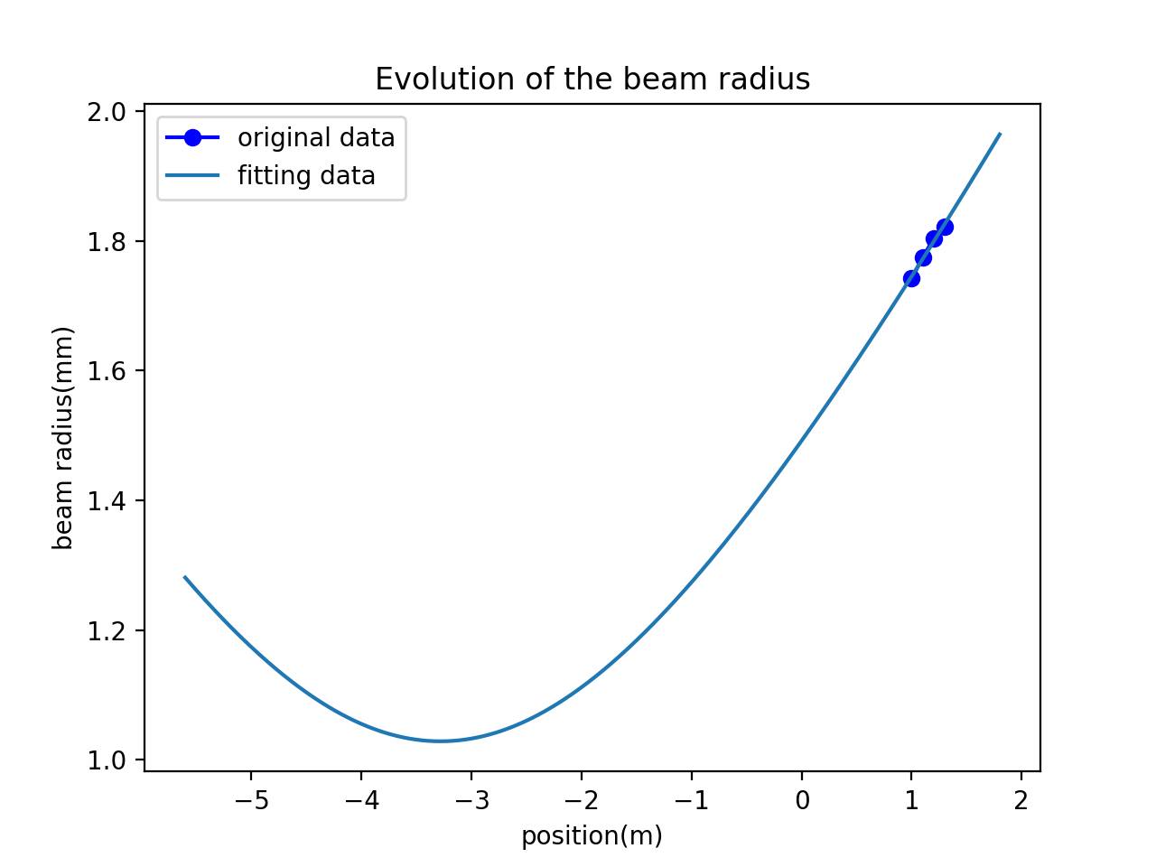
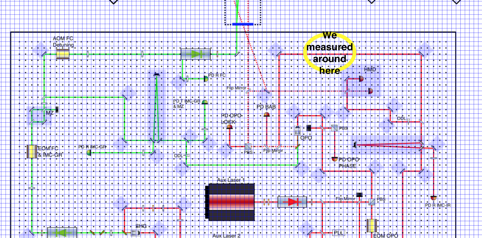
Because yesterday's measurement doesn't match previous result. I decided to do the simulation for the infrared. However, I found there is a lens without label on it. So Eleonora suggested me to consult yuefan about this. And yuefan said it is used for the test of mode cleaner. So we decide to remove it. After removing it, we want to check the beam waist again.
See attached figure 1, we found the beam waist was very far from where we did the measurement.(The measurement position is shown on the attached figure 2) And the beam waist is about 1mm. The beam waist fit the result of OptoCad. However the beam waist position doesn't fit the result of OptoCad. As you can see the attached figure 3, the highlight part show that the beam waist is around 8 meters ahead of R1. This R1 is the dichroic mirror which is used to combine green and infrared. But the measurement of beam waist tells us the distance between them is around 6 meters.
According to attached figure1, the beam size at Faraday Isolator should be around 2mm in radius. This measurement is totally different from the requirement of e-log 441. E-log 441 gave us the beam size around Faraday Isolator should be 1.368mm. No matter it is diameter or radius, it doesn't agree what we measured today.
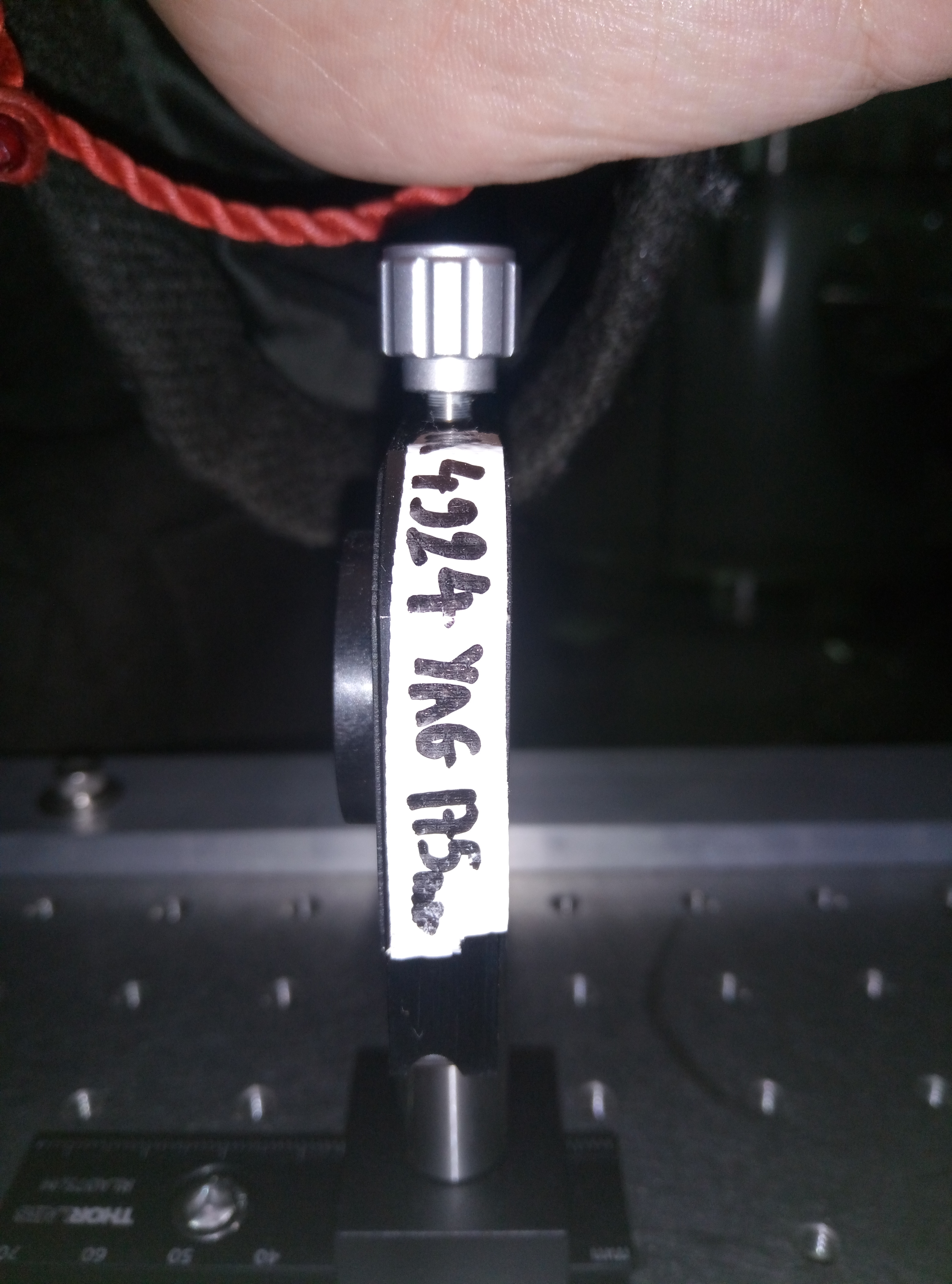
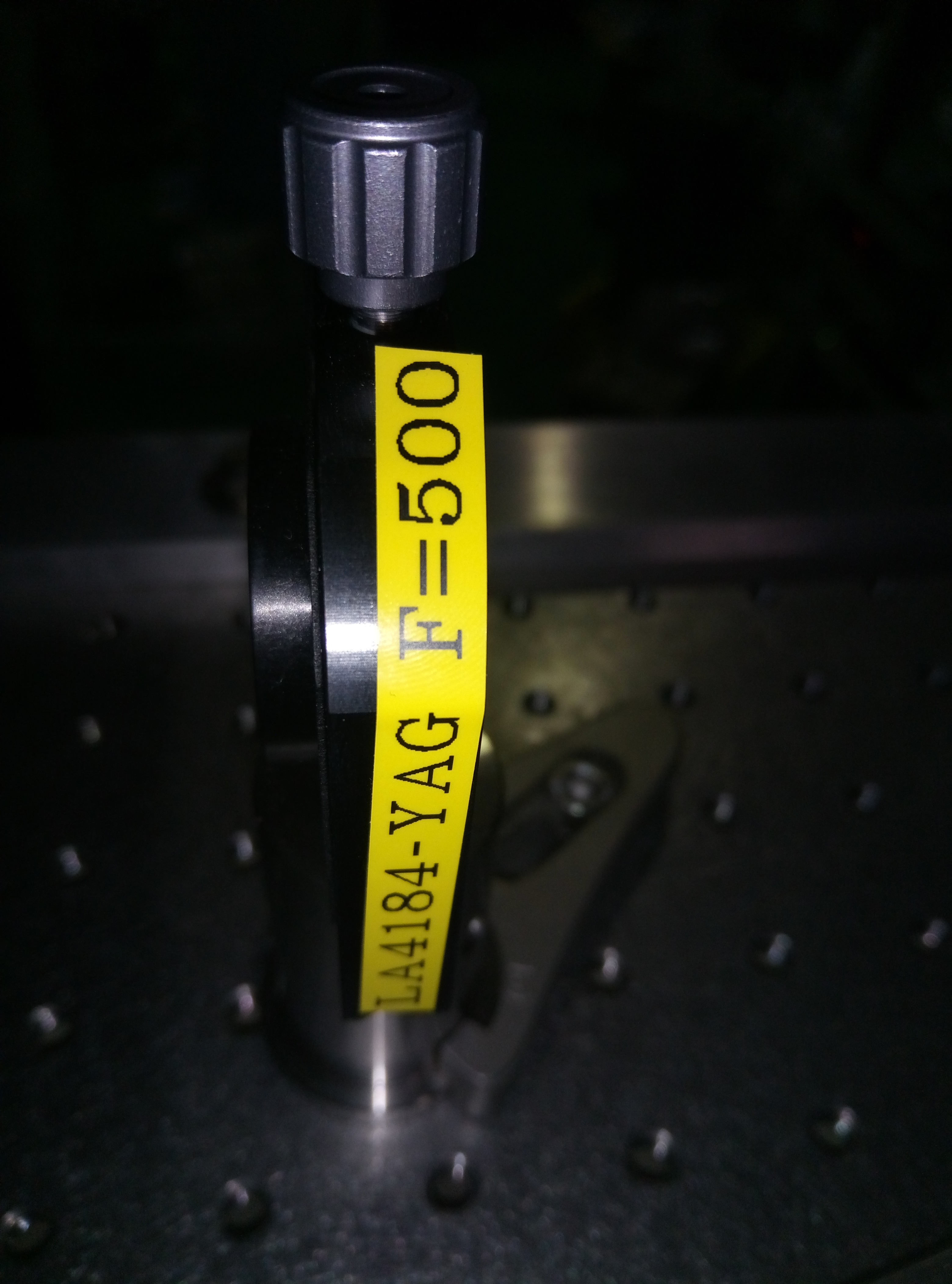
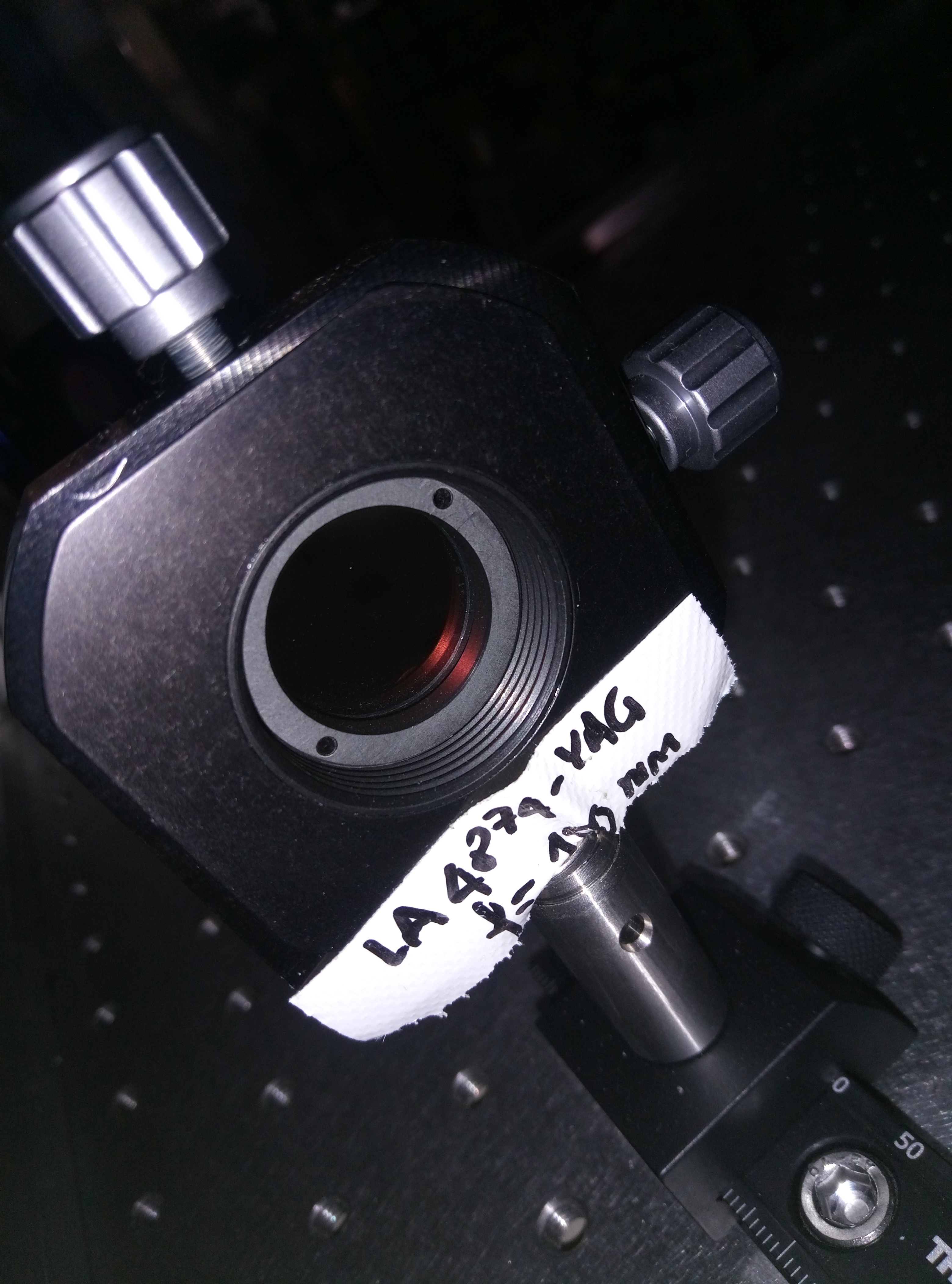
Besides, I just found there is e-log 442 which tells us the setting of infrared telescope. We can see from there, the design is using leses f500, f300 and f350. However I found the actual lenses we are using is f500, f150 and f175. See attached last three pictures to check this.
Today I measured it again. Since the last measurement seems to be limited in a small region, I tried to expend the region this time. The result is shown here.
And now, we have four lenses on the infrared path. They are f500, f150, f175 and one without lable. Is this the same with previous situation?