NAOJ GW Elog Logbook 3.2

The KAGRA QPDs will be used for the TAMA OpLev.
In order to prepare their installation, I checked the available space for these QPDs.
The most critical one is the Input Mirror ones : there is only a lateral space of 70 mm between the various beams. Also, the longitudinal space between the first QPD and the end of the window optical table is 60 mm.
As the KAGRA QPDs have horizontal size at the order of 62 mm (and vertical 73 mm) , it will be required to design our own cover box.
For all the others OpLev there sould not be any critical space constraints
We also took some measurement of PD spectrum.
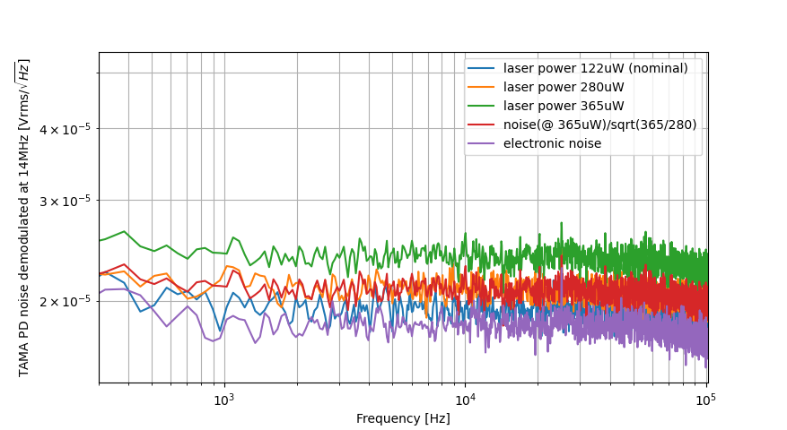
Attached figure 1 shows the measurement of CC1 PD noise after demodulation for different incident power. In this figure, op-amp LMH6624, R1 1.1kOhm, R2 13kOhm are used.
We could see that noise becomes to be shot noise limited when laser power reaches around 300uW. Therefore, I confirmed that electronic noise was still limiting in this case. Then I checked again the simulation, which shows the noise is limited by the resistor. However, according to the simulation, shot noise should start to limit after laser power reaching 3mW.
360mV pk-pk corresponds to -4dBm, after a 21dB amplifier, it becomes 17dBm (50mW). According to the specification of frequency mixer (ZX05-1L-S+), it may have permanent damage if the RF power is more than 50mW. Therefore, we have been already reaching this threshold due to this 160~180MHz oscillation. This seems to be the reason of demodulation problem when (R1=11Ohm, R2=130 Ohm) are used. A filter to remove this oscillation may help to solve this problem.
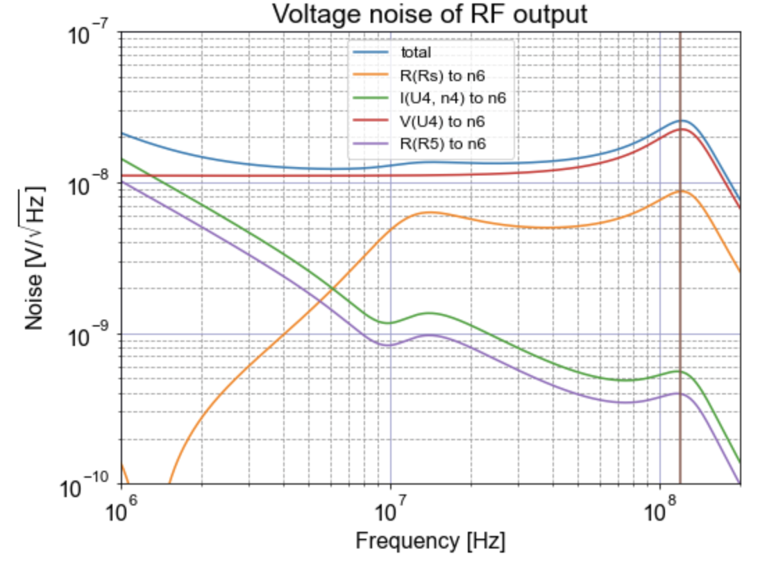
We checked again the simulation of this PD up to 200MHz (see attached figure 1). It has voltage noise increase around 120MHz, but this peak is not very sharp. Therefore, we still don't quite understand why we have such large oscillation when (R1=11Ohm, R2=130 Ohm) are used.
Marc, Yuhang
Today we pursued the investigation of this photodiode. Especially, we investigated if there is some offset present that could saturate the mixer used for the demodulation.
First (with high resistors of previous entry) we measured an offset of -1.68V.
Adding a DC block reduces it below 2mV.
Then, we replaced the resistors (low in previous entry) :
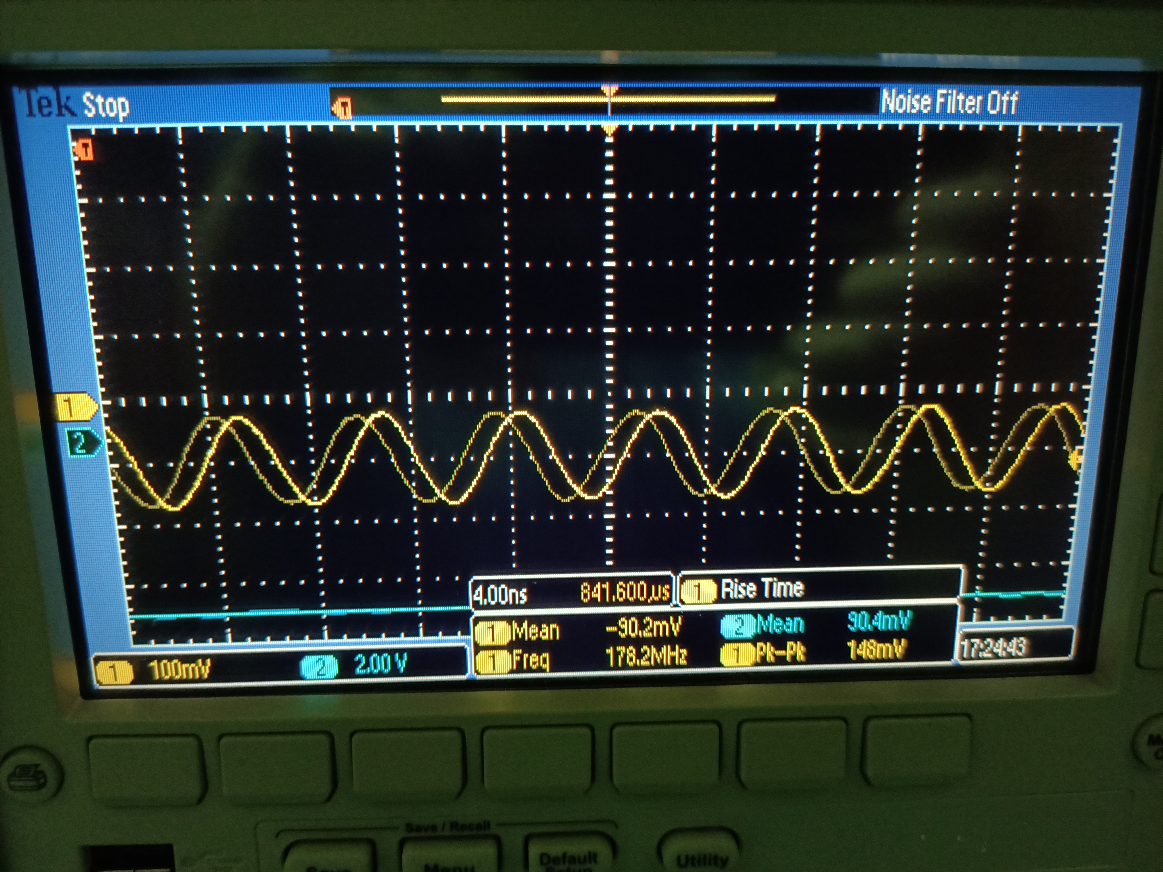
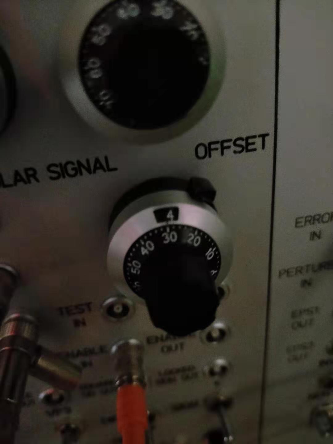
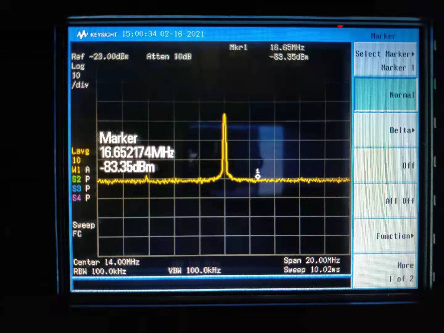
We measured an offset with mean value -90mV and also a clear frequency modulation around 180MHz and peak to peak around 148 mV (Fig 1)
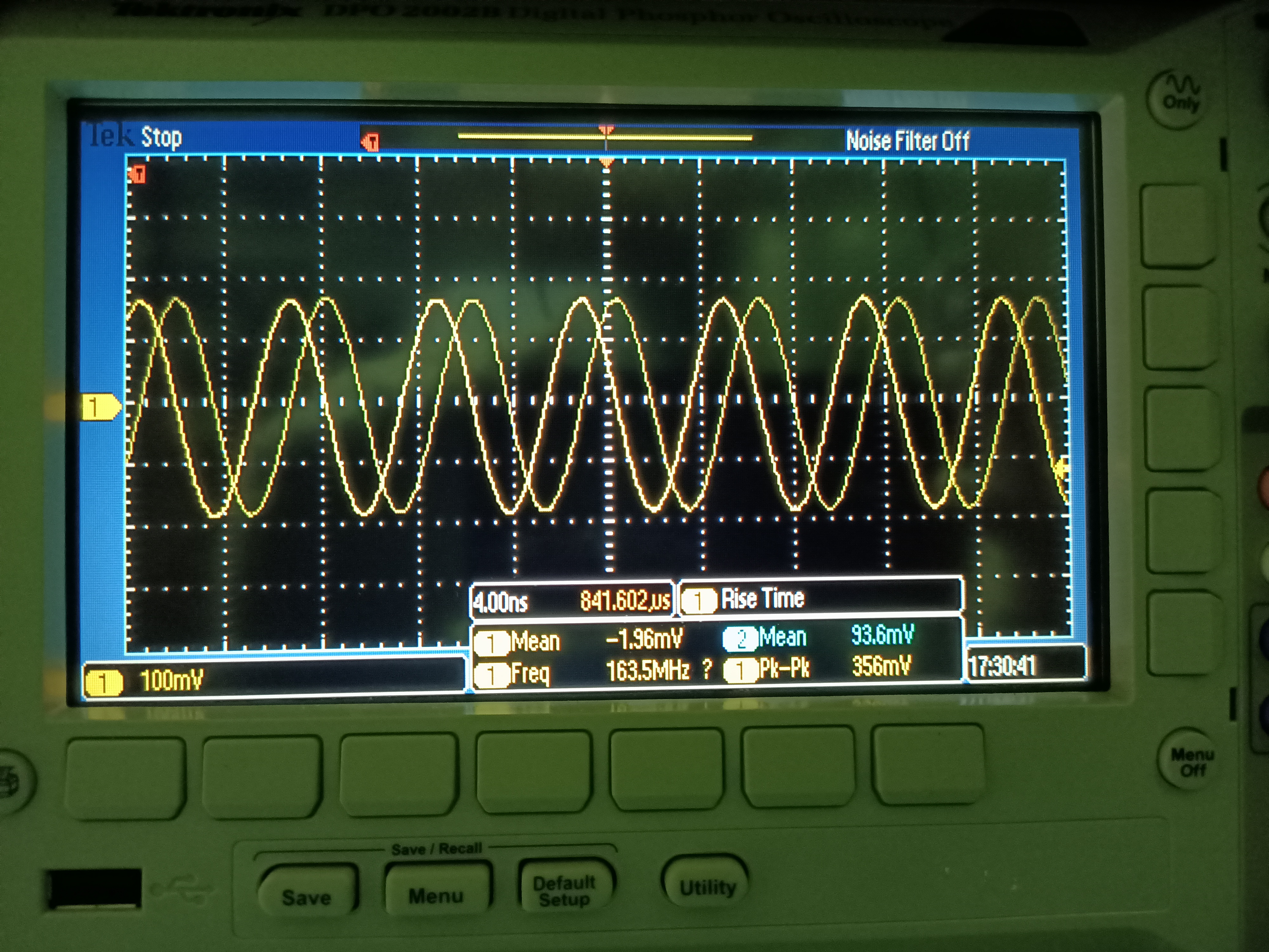
Adding a DC block reduced the offset mean value to -2mV but the signal around 160MHz had an increased peak to peak amplitude around 360mV (Fig 2)
As there is a 20dBm amplification after the mixer, this high frequency signal is larger than the 14MHz one (at -10dBm) and is close to saturation of the mixer.
We'll try to compare this result with simulation (performed up to 100 MHz for now)
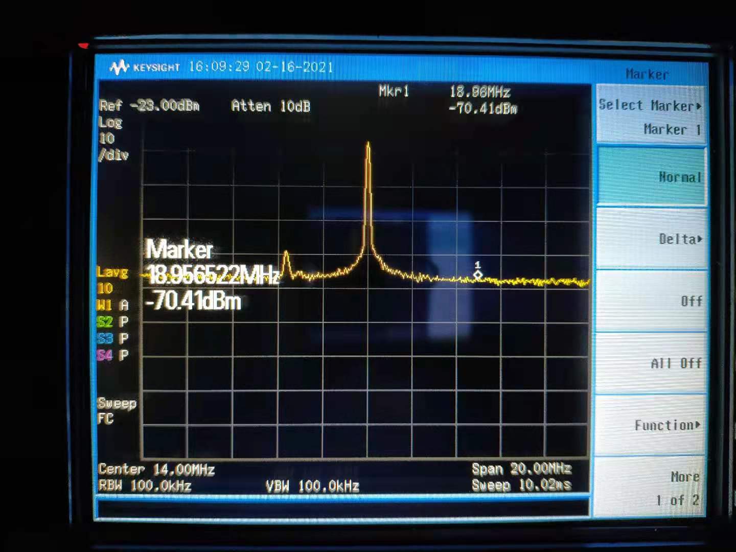
Today, we checked again this moving peak. At the beginning, this moving peak appears to be very close to 14MHz again. But after 10min, on spectrum analyzer, it goes away from 14MHz peak and stay there until almost 30min.
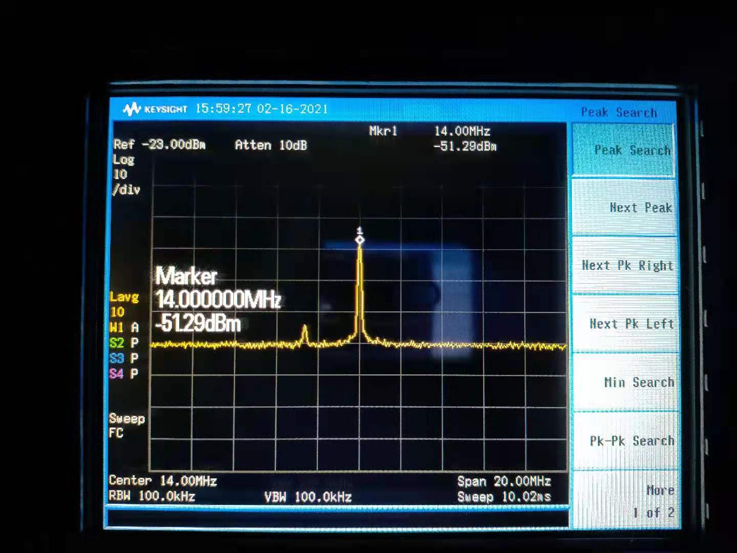
The CC1 PD is used to detect RF signal at 14MHz. While checking this 14MHz signal peak on the spectrum analyzer, I found another peak that is moving in the frequency domain, and its peak height also changes.
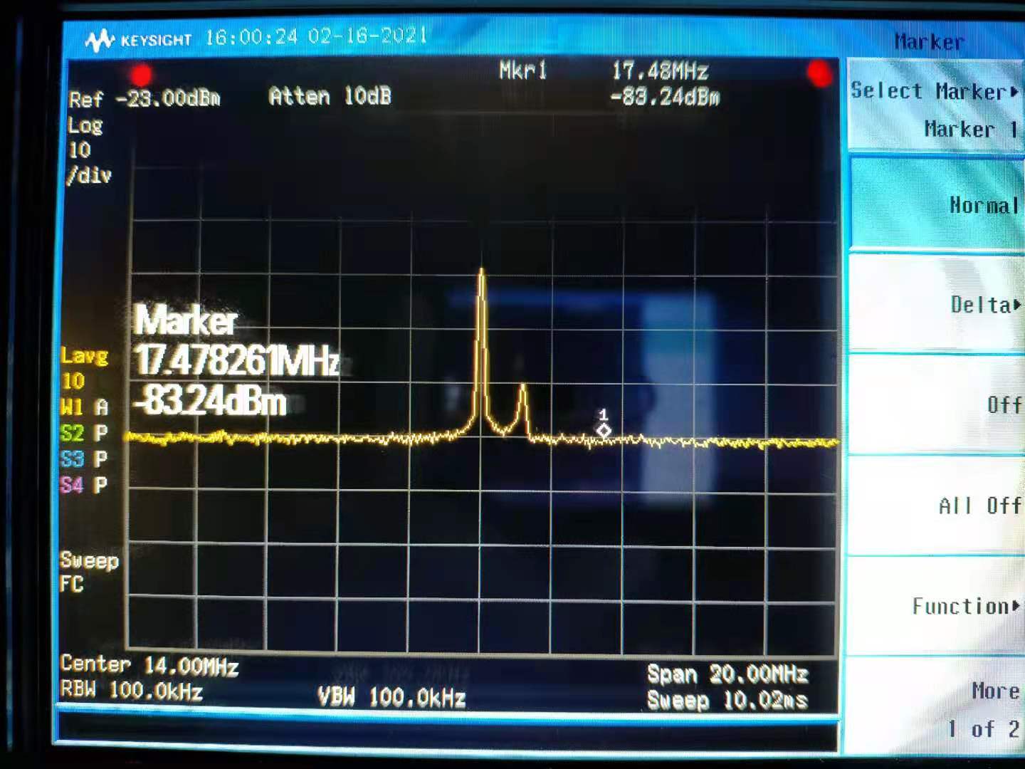
This moving peak can reach a level of almost about -63dBm (before amplification). The frequency of this moving peak seems to be +/- 10MHz around 14MHz. Besides, it seems to become even larger when it approaches the 14MHz peak. More importantly, the RF signal from CC1 PD is only -51.3dBm (before amplification), which means that this moving peak may introduce non-negligible noise into the CC1 loop. There is a movie in this link shows the situation.
I also found this peak still exists even when all optical cavities are unlocked. This situation is in the movie in this link (after 20dB amplification). At around 8 second, I switched off CC PLL, the moving peak disappeares. So it seems this moving peak is related with PLL loop.
I also confirmed that this peak is not RF signal cross talk. Because when I block the light incident on CC1 PD, this moving peak disappears.
Today, we checked again this moving peak. At the beginning, this moving peak appears to be very close to 14MHz again. But after 10min, on spectrum analyzer, it goes away from 14MHz peak and stay there until almost 30min.
In the CC1 PD (TAMA 14MHz resonant PD), LMH6624 is being used (this modification was done in 2019). However, a relative large resistor (1.1kOhm) is being used to connect + of LMH6624 and ground. This connection should introduce lots of thermal noise. Therefore, I would like to replace it with a 10Ohm resistor. Accordingly, the other resistor which is used to amplify signal is changed from 13kOhm to 130Ohm.
Before this resistor replacement, I made several measurements as a benchmark. The green pump power used in this test is always 30mW.
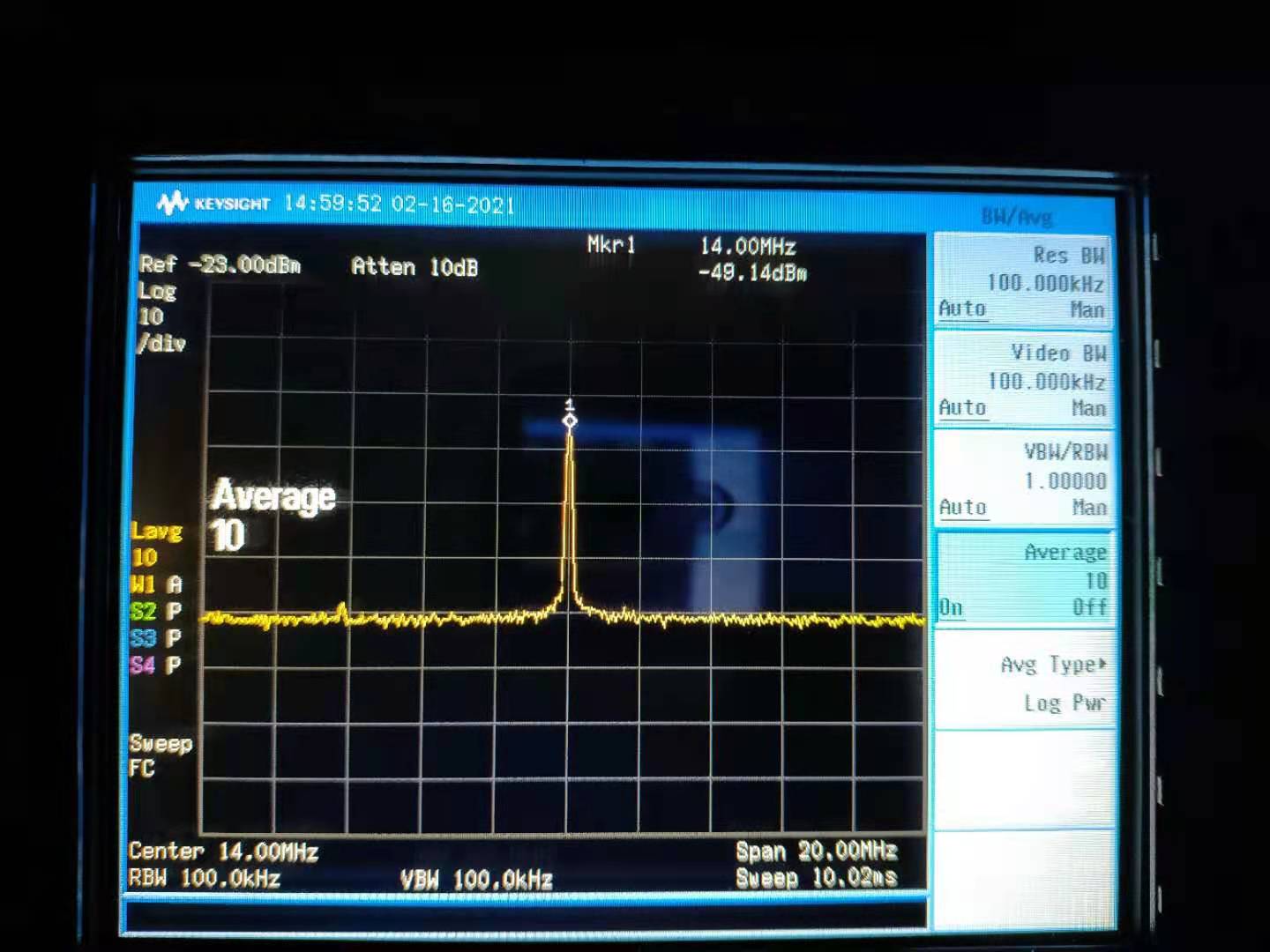
Signal from PD: -51.3dBm. Noise from PD: -83.2dBm (SNR: 31.9dB)
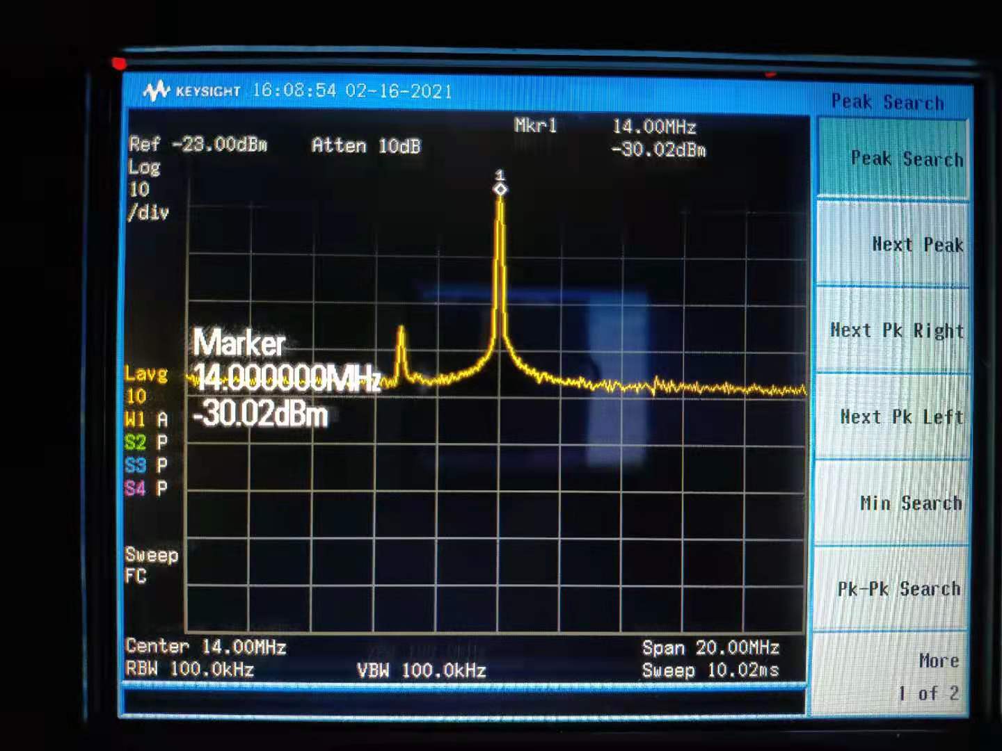
SIgnal after amp: -30.0dBm. Noise after amp: -70.4dBm (SNR: 40.4dB)
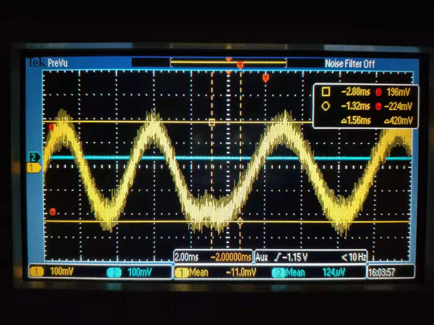
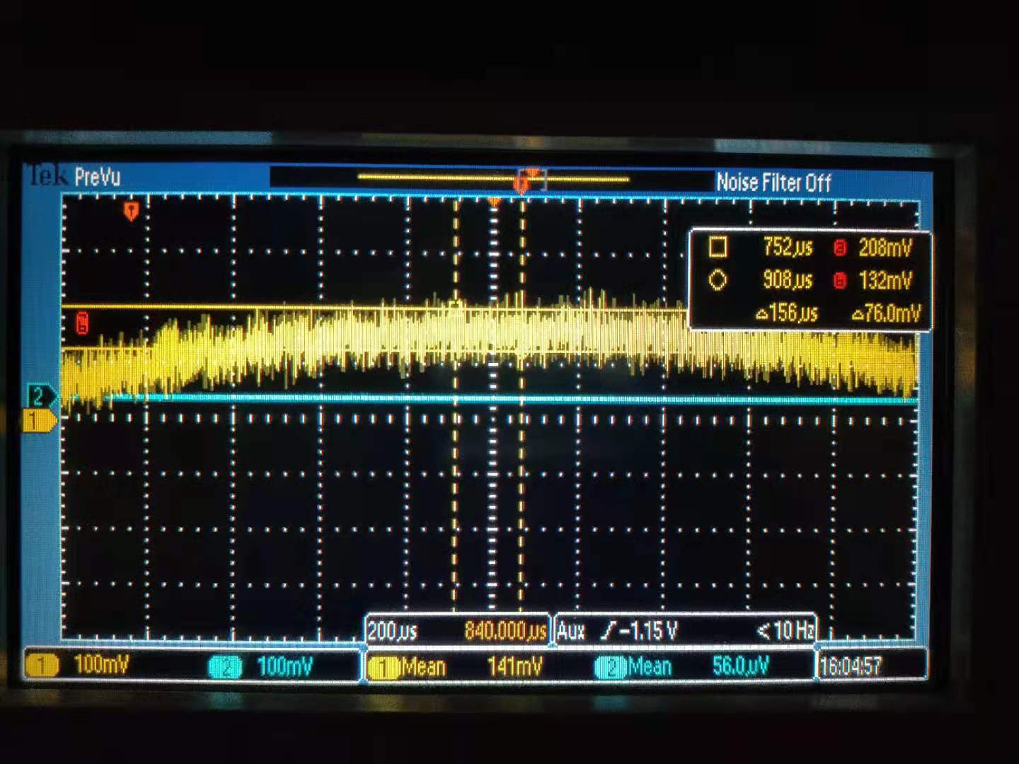
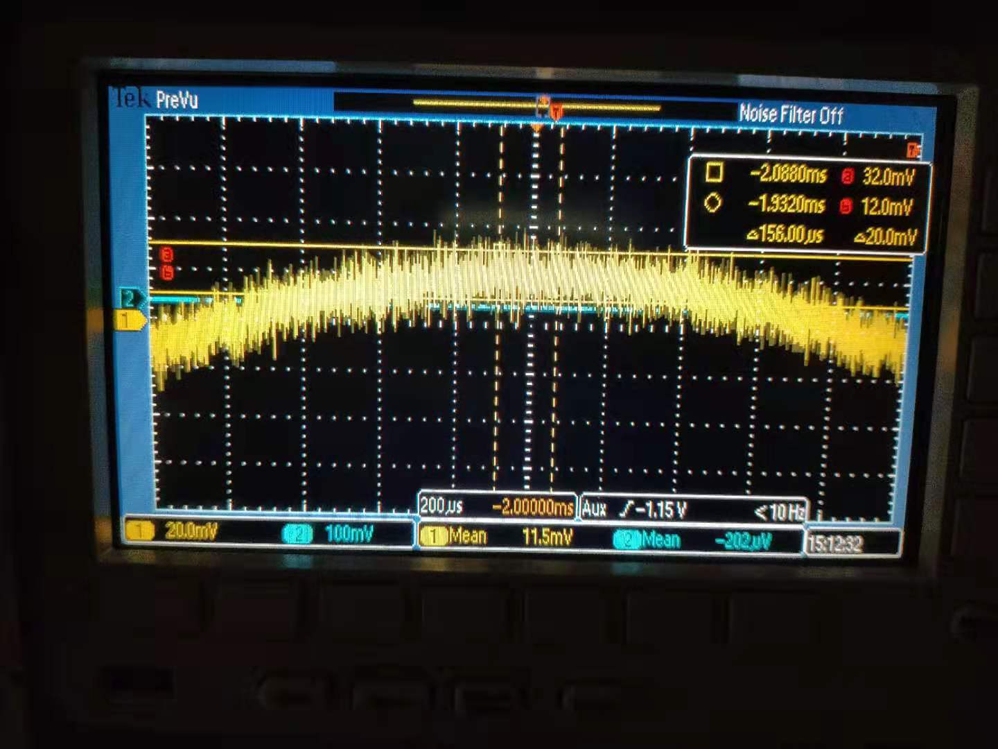
After demodulation, the signal time-series is measured by oscilloscope. Its pk-pk is 420mV. Thickness of singal line is 76mV. (SNR: 5.5)
After resistor replacement, the same measurements were also performed. And I got:
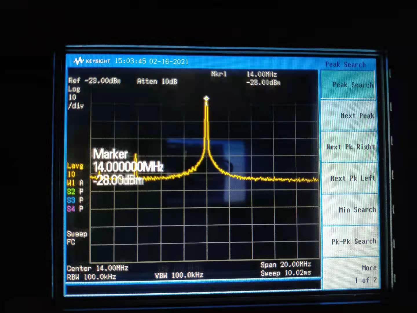
Signal from PD: -49.1dBm. Noise from PD: -83.4dBm (SNR: 34.3dB)
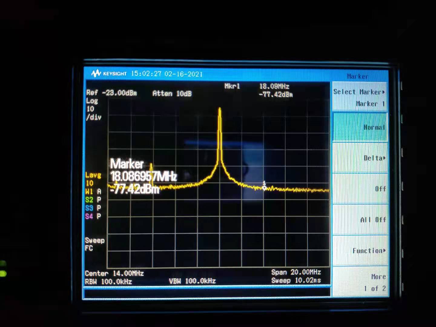
SIgnal after amp: -28.0dBm. Noise after amp: -77.4dBm (SNR: 49.4dB)
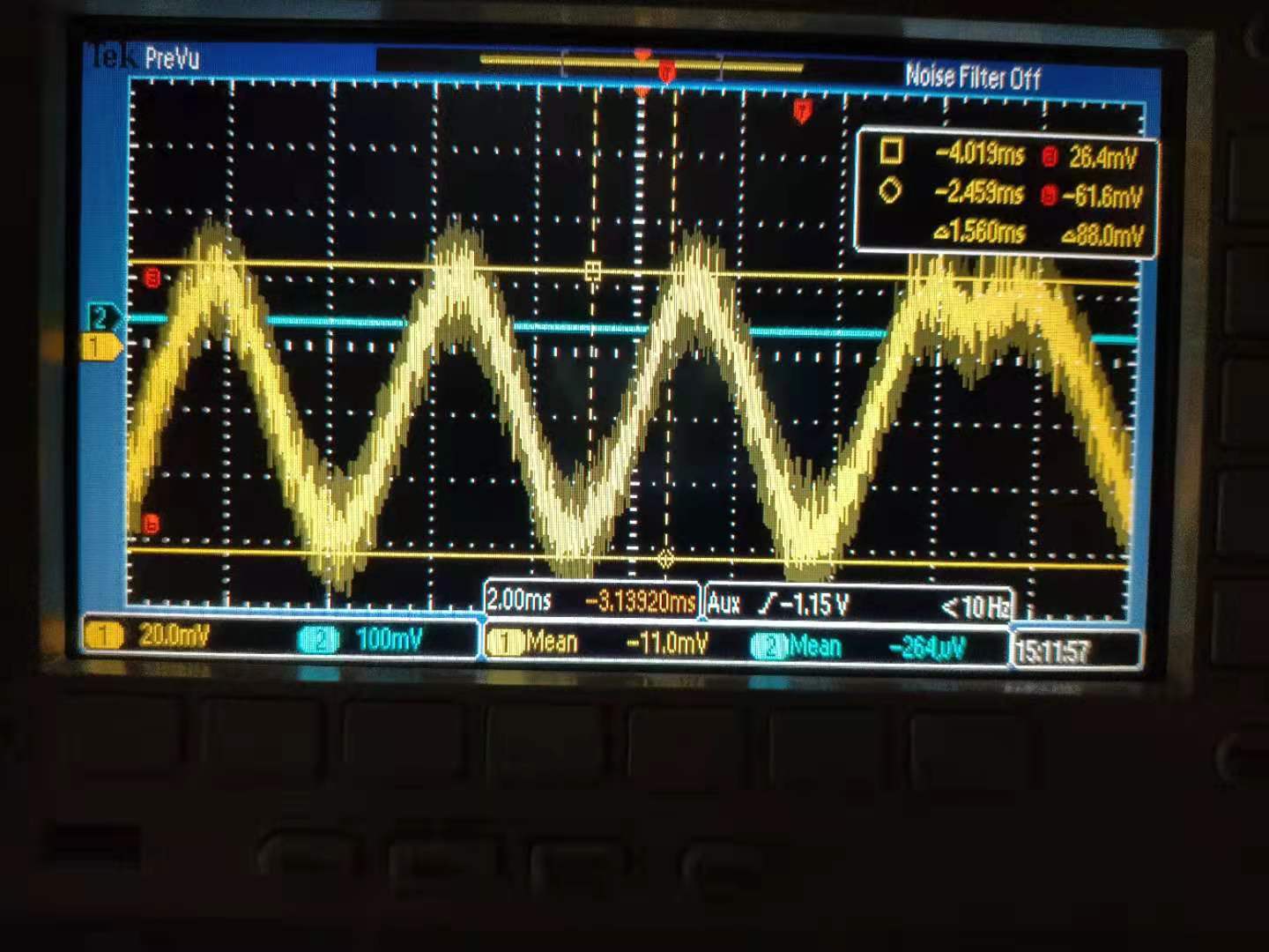
After demodulation, the signal time-series is measured by oscilloscope. Its pk-pk is 88mV. Thickness of singal line is 20mV. (SNR: 4.4)
(The demodulated signal is a bit strange. Although the 14MHz peak becomes larger but the demodulated signal is smaller.)
It seems the SNR improvement is obvious by replacing resistor. However this improvement is only visible before demodulation. The demodulated signal (checked from oscilloscope) even becomes worse. For demodulation, we upgraded DDS to provide saturated LO for each demodulator/mixer. But maybe we still have some issues about signal demodulation.
I have already changed resistor back to the original situation. And put CC1 PD back.
Marc, Yuhang
Today we pursued the investigation of this photodiode. Especially, we investigated if there is some offset present that could saturate the mixer used for the demodulation.
First (with high resistors of previous entry) we measured an offset of -1.68V.
Adding a DC block reduces it below 2mV.
Then, we replaced the resistors (low in previous entry) :
We measured an offset with mean value -90mV and also a clear frequency modulation around 180MHz and peak to peak around 148 mV (Fig 1)
Adding a DC block reduced the offset mean value to -2mV but the signal around 160MHz had an increased peak to peak amplitude around 360mV (Fig 2)
As there is a 20dBm amplification after the mixer, this high frequency signal is larger than the 14MHz one (at -10dBm) and is close to saturation of the mixer.
We'll try to compare this result with simulation (performed up to 100 MHz for now)
360mV pk-pk corresponds to -4dBm, after a 21dB amplifier, it becomes 17dBm (50mW). According to the specification of frequency mixer (ZX05-1L-S+), it may have permanent damage if the RF power is more than 50mW. Therefore, we have been already reaching this threshold due to this 160~180MHz oscillation. This seems to be the reason of demodulation problem when (R1=11Ohm, R2=130 Ohm) are used. A filter to remove this oscillation may help to solve this problem.
We checked again the simulation of this PD up to 200MHz (see attached figure 1). It has voltage noise increase around 120MHz, but this peak is not very sharp. Therefore, we still don't quite understand why we have such large oscillation when (R1=11Ohm, R2=130 Ohm) are used.
We also took some measurement of PD spectrum.
Attached figure 1 shows the measurement of CC1 PD noise after demodulation for different incident power. In this figure, op-amp LMH6624, R1 1.1kOhm, R2 13kOhm are used.
We could see that noise becomes to be shot noise limited when laser power reaches around 300uW. Therefore, I confirmed that electronic noise was still limiting in this case. Then I checked again the simulation, which shows the noise is limited by the resistor. However, according to the simulation, shot noise should start to limit after laser power reaching 3mW.
Marc, Yuhang
We tried to recover the filter cavity following the earthquake of Friday night.
We used pico-motors to move back the mirrors to a good position.
However, we found out that the BS mirror can not be moved enough using only pico-motors.
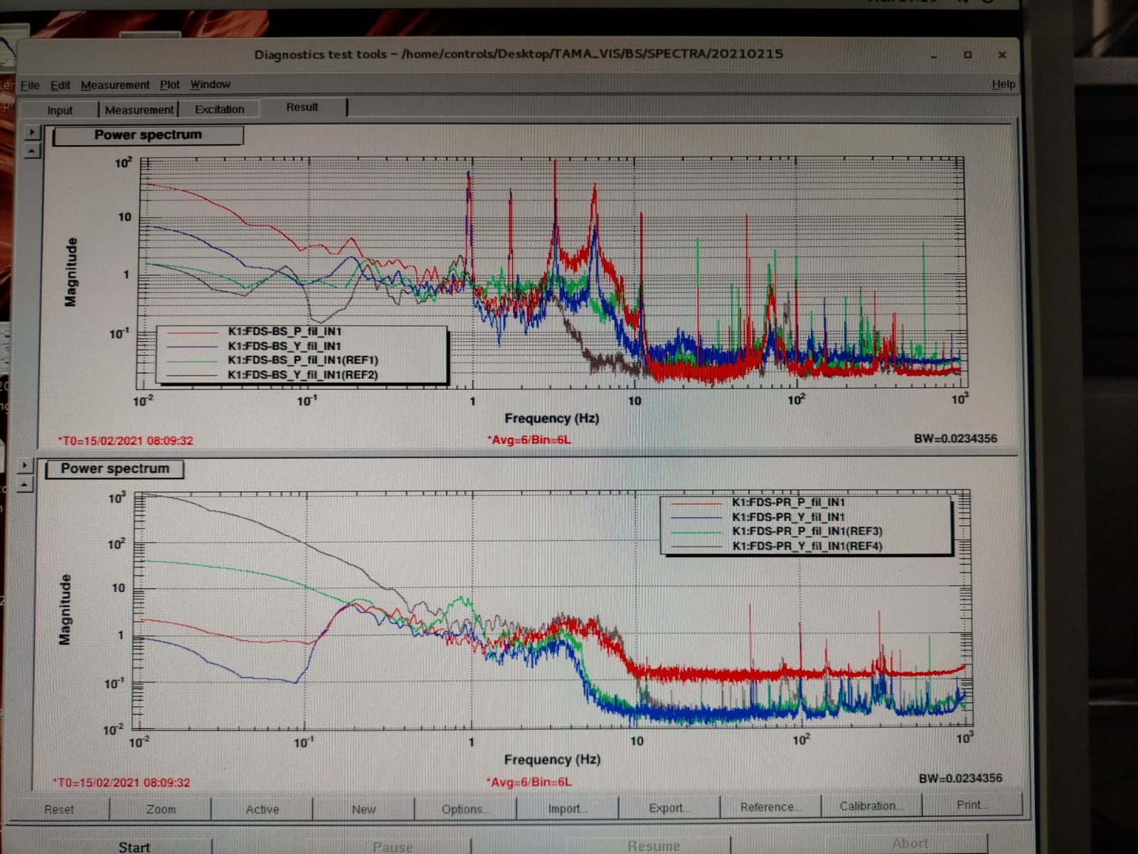
The attached figure shows the BS pitch and yaw from the OpLev with the brown and green corresponding to reference spectra and red and blue the current situation.
We can see the appearances of several peaks that hint that the BS magnets are touching the coils.
It means that we will have to open this chamber.
Marc, Michael and Yuhang
We were guessing that back scattered noise is not from suspended mirror motion in elog2366. To further understand where the low frequency noise comes from, we did more checks. I think the understandling is much more clear now.
From the check we did in last few days, in conclusion, the low frequency noise has two components: back scattered noise from lens inside homodyne, local oscillator amplitude noise (or lo jittering).
In detail:
Last week, we tilted the lenses inside homodyne as what I did together with Eleonora. We found low frequency noise was reduced inside squeezing spectrum. But there were still residual noise. To understand where the residual noise from, we checked many noise spectrums and we found the IRMC reflection has some peaks very similar with some peaks inside squeezing spectrum. Besides, we also tried again to cover homodyne better from potential scattered light, which didn't improve the situation. Since the IRMC reflection indicates the amplitude noise of local oscillator, we start to suspect this amplitude noise to be the reason of part of low frequency noise inside squeezing spectrum.
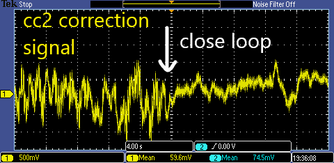
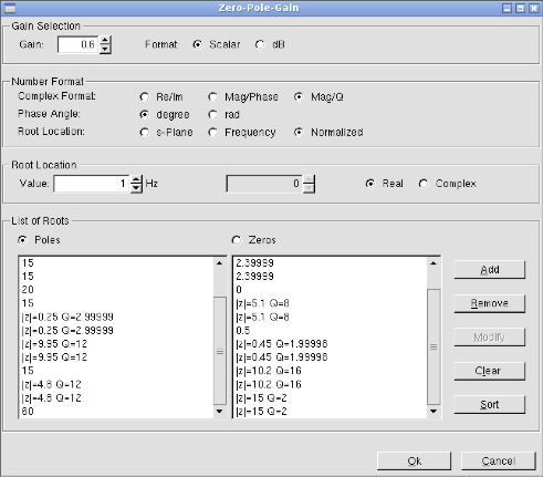
The local oscillator amplitude noise (jittering) has been preliminarily investigated together with Yaochin (elog 1904). We found it to come from the large correction signal sent to CC2 phase shifter. Besides, we have tried to offload this correction by sending part of this signal to filter cavity input mirror. However, it was not successful at that time. To improve this situation, I had a look of the filter design for filter cavity AC local control. Especially, I investigated the fitlers designed by Eleonora and Ettore. I copied this filter, modified it, and used it for feeding back CC2 correction signal to filter cavity input mirror. In the end, we could offload quite a lot of correction signal sent to CC2 phase shifter. Attached figure 1 shows the difference of CC2 correction signal when the loop (CC2 correction send to filter cavity input mirror) engaged.
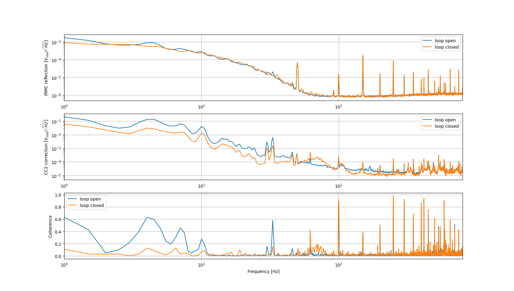
After that, we compared again the CC2 correction signal and IRMC reflection with and without this control loop (CC2 correction send to filter cavity input mirror). Attached figure 2 shows their spectrums and coherence. We found the IRMC reflection has smaller peaks at low frequency (smaller than 10Hz). But there were not much difference above 10Hz. Besides, It is diffcult to tell if the amplitude noise is reduced or not in this measurement because IRMC reflection should be mostly limited by shot noise. We can also notice an increase of coherence between 60 and 80Hz. This proves the effect of control loop for local oscillator amplitude noise at high frequency (tens of Hz).
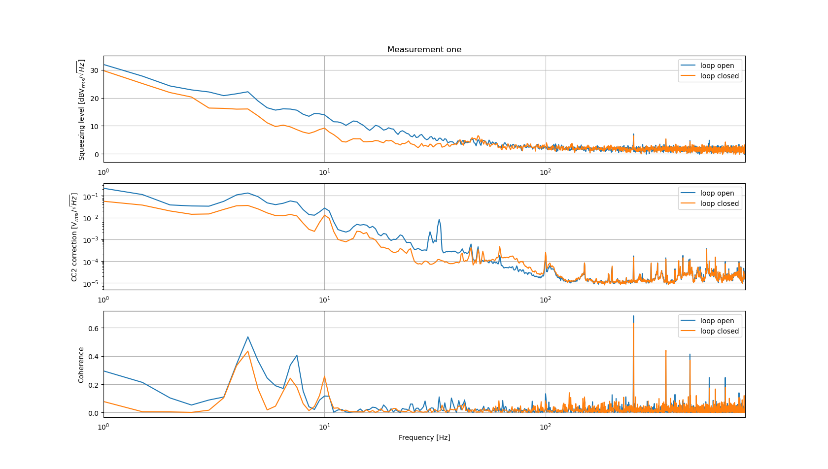
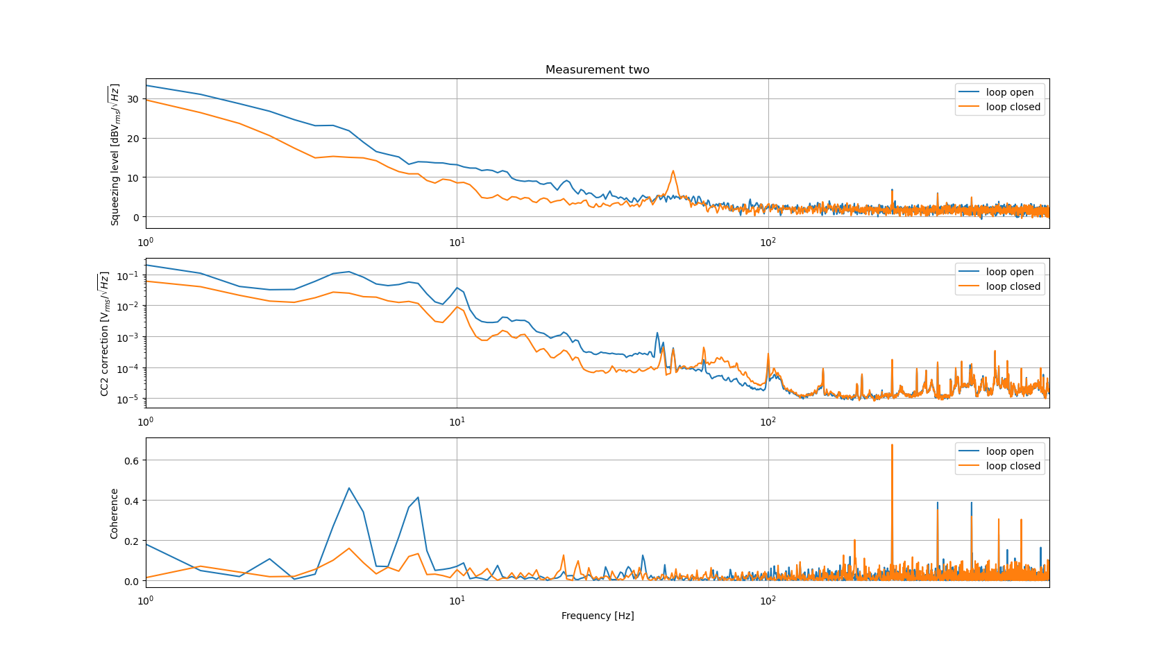
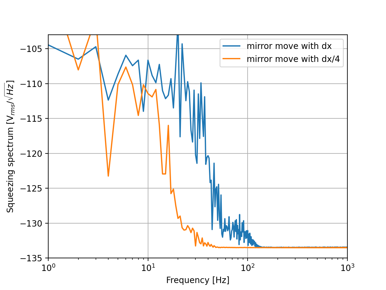
Most importantly, we checked twice the squeezing spectrum and CC2 correction signal with and without this control loop (CC2 correction send to filter cavity input mirror). Attached figure 3 and 4 shows the two measurements of their spectrums and coherence. In the squeezing spectrum, a clear decrease of low frequency noise is visible when the loop is engaged. The decrease of squeezing low frequency noise is very similar with the decrease of cc2 correction signal. So we suppose, in this configuration, the local oscillator amplitude noise is dominating. There are still test to be done to validate this guess. But I made a simulation of this back scattered noise (formula from Irene Fiori or many other papers). From this simulation, the reduction of total motion will just make the whole shoulder of back scattered noise move to lower frequency. At the same time, the low frequency shoulder height should be kept the same level. (see figure 5) And this is not the case of our measurement. So we could also conclude, in the current experimental configuration, low frequency noise behaves more to be local oscillator amplitude noise.
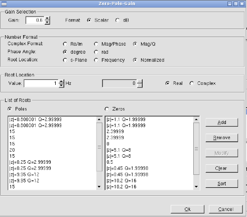
The control filter configuration is in figure 6 and 7. Note that we could see from the spectrum of CC2 correction signal that, the unity gain frequency should be around 50Hz. We are introducing an obvious peak around UGF. So the filters still have room to be improved.
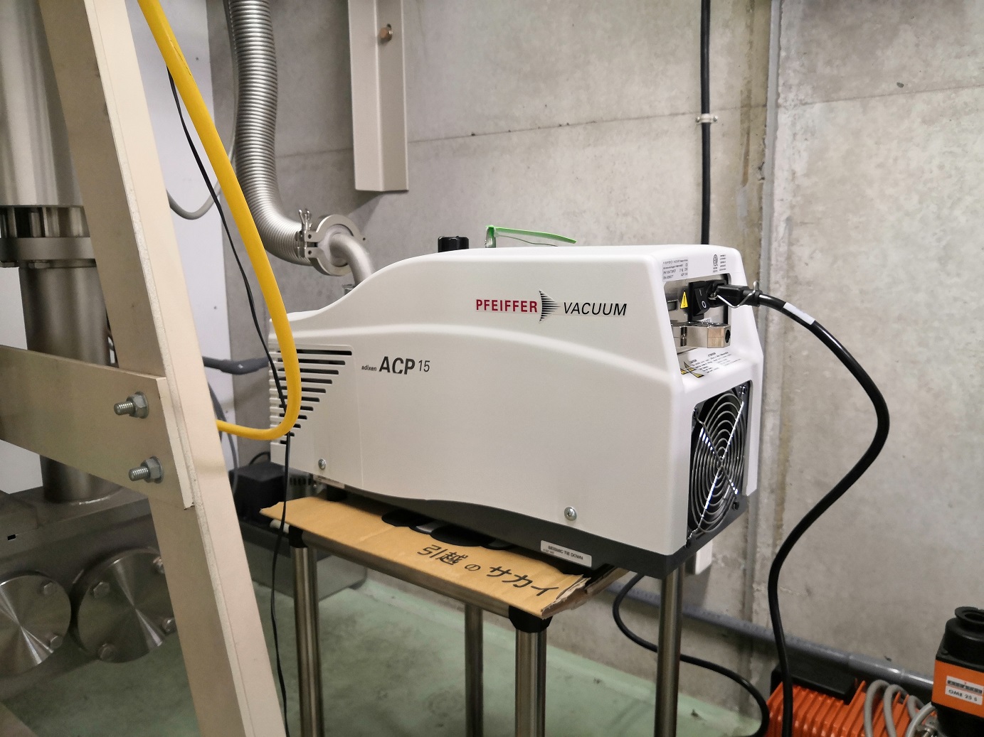
I confirmed the status of vacuum pumps in the south end (see klog).
- The DRY pump DSP500 was broken with the alarm #05 "MP STEP". It is necessary to repair by the company.
- The pump was replaced to a new DRY pump ACP15.
- The TMP was recovered with the new pump. The gate valves to the tube were opened.
You mean you couldn't find a 20 Hz line in the backscattering spectrum?
Marc and Yuhang
Recently, it was realized that back scattered noise is more than what we had (elog2350). According to the fact that back scattered noise is almost the same when end mirror is misaligned, also it can be reduced when lens (inside arm of homodyne) are misaligned, we suppose the reason of this back scattered noise as following. Firstly, homodyne's LO hits on two lens in the two arms. After that, some power is back reflected and propagates to many optics (such as PR, BS, INPUT...)
To understand better how the mirror motion is causing back scattered noise, a line (for example, 20Hz sine wave) is sent to input mirror to excite a fixed frequency back scattered noise. When sending this line to INPUT, we would like to know how much we are moving INPUT mirror. But we couldn't find this information, so we did the following calibration.
1. We use diagui to send amplitude 100 to input mirror channel: INPUT_ZCORR_fil_exc.
2. Since FC is locked, we check correction signal sent to main laser. The correction signal is 103uV.
3. The calibration factor is 100*1e6*2/1e12 [V/m]
4. We get 20.6nm, which is less than half wavelength.
Since we could see the injected line in correction signal, this means we are exciting INPUT more than its residual motion. If the motion of input mirror is dominating back scattered noise, we should be able to see a peak at the same frequency with the line sent to INPUT.
Therefore, we think the back scattered noise is limited by motion of in-air bench.
You mean you couldn't find a 20 Hz line in the backscattering spectrum?
Yes, I checked this voltage. With current power, it is 2.8V. This is already quite close to 4V, so we don't have much space for improvement.
Anyway, I tried to remove one ND filter to have 4V, but the spectrum is quite similar with the 2.8V one.
PR and BS can accpet more power, but most of the light was lost since the suspended mirror surface is not HR for 635nm. So we couldn't have more power.
According to the manual, thorlabs PSD (which are installed on the input and on the end mirror) should have a power level so that the SUM output voltage is ≤ 4 V.
Is this the case?
BS and PR are equipped with different PSD (TAMA ones) which can accept higher power.
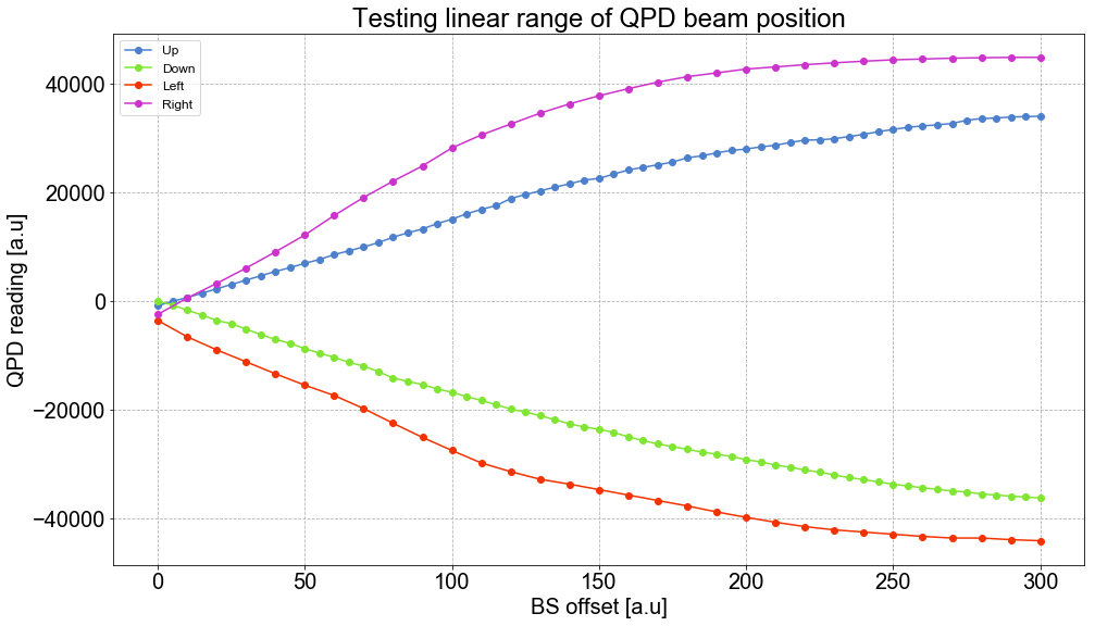
After the measurement of the QPD spectrum with BS oplev in elog2532, we then measured the QPD linear range. We centered the beam on the QPD and checked the linear range while offsetting the beam position up, down, left and right.
When returning the beam position to "zero", the QPD reading didn't return to the zero value measured at the start of each run. So there is a bit of effect from suspended optics drift. This is why I split the data into 4 directions rather than just pitch and yaw.
Also, the QPD readings have a variation of about +/- 200 in pitch and ~+/- 300 in yaw.
I made a measurement of oplev laser power for PR/BS/INPUT/END.
They are 270uW (PR), 320uW(BS), 70uW(input) and 107uW(end).
According to the datasheet of thorlabs PSD, the maximum power should be around 66uW.
Oplev laser power has been set in order to be compliant with PSD specs. Since the laser diode that we use doesn't have the possibility to control the power, ND filter were added to this purpose.
User manual of the PSD can be found here: http://www2.nao.ac.jp/~gw-elog/osl/uploads/278_20160721110810_pdp90a.pdf
Michael and Yuhang
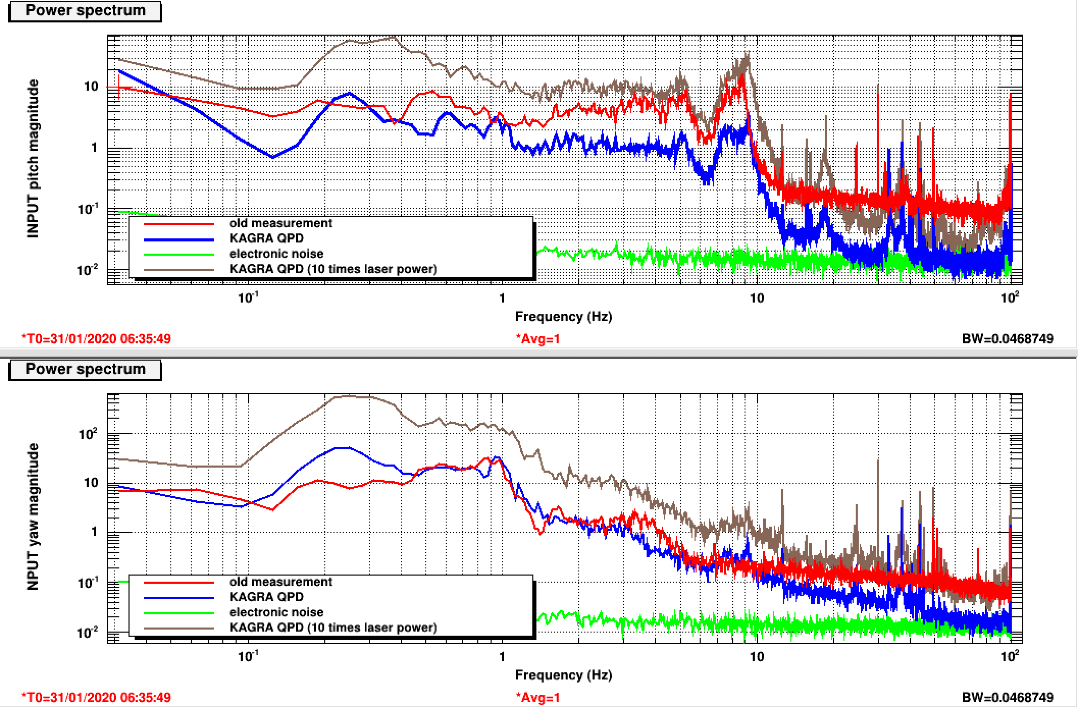
To test the available space and compare the performance of KAGRA QPD with thorlabs PSD, we did the test for INPUT.
1. We found all mirrors are not fixed well inside the mirror mounts. For example, we could easily push them out by hand.
2. We found several ND filters were used to reduce oplev light power. We took measurement with all ND filters or none of them.
The comparison is in figure 1. We could see that KAGRA QPD has a better SNR while the same oplev laser power is used. By increasing oplev laser power, an even better SNR could be achieved. The spectrum below 10Hz is quite similar but some new peaks appear at high frequency.
Apart from these, I have some questions.
0. Are we aiming for a better SNR with KAGRA QPD? If so, why don't we just increase oplev laser power?
1. Why we use ND filters to reduce oplev laser power? Is there any limitation for oplev laser power?
2. Are the screws to fix mirror inside mirror mount easily loosen by themselves? If so, we should check for other oplevs and mirrors on bench.
Note: after this test, we have bring system (simulink files and oplev set-up) back to the original situation.
Oplev laser power has been set in order to be compliant with PSD specs. Since the laser diode that we use doesn't have the possibility to control the power, ND filter were added to this purpose.
User manual of the PSD can be found here: http://www2.nao.ac.jp/~gw-elog/osl/uploads/278_20160721110810_pdp90a.pdf
I made a measurement of oplev laser power for PR/BS/INPUT/END.
They are 270uW (PR), 320uW(BS), 70uW(input) and 107uW(end).
According to the datasheet of thorlabs PSD, the maximum power should be around 66uW.
According to the manual, thorlabs PSD (which are installed on the input and on the end mirror) should have a power level so that the SUM output voltage is ≤ 4 V.
Is this the case?
BS and PR are equipped with different PSD (TAMA ones) which can accept higher power.
Yes, I checked this voltage. With current power, it is 2.8V. This is already quite close to 4V, so we don't have much space for improvement.
Anyway, I tried to remove one ND filter to have 4V, but the spectrum is quite similar with the 2.8V one.
PR and BS can accpet more power, but most of the light was lost since the suspended mirror surface is not HR for 635nm. So we couldn't have more power.
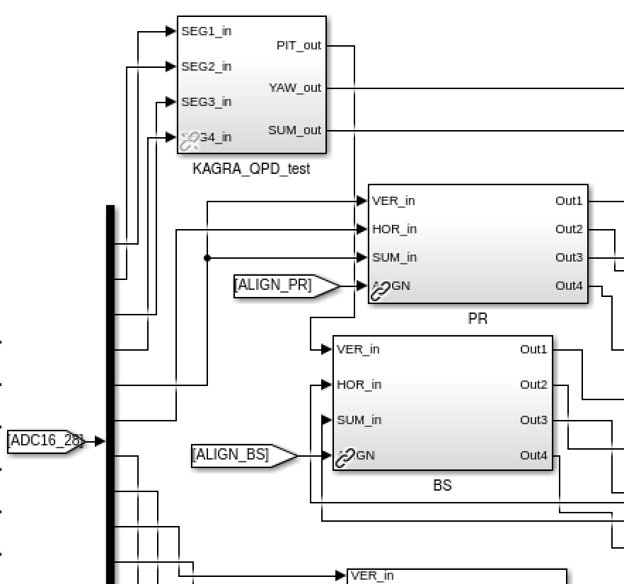
We have used channel 17-20 of the lower AA chassis, which was originally PR p/y/s and BS p. The four signals from four segments of KAGRA QPD are using them.
A marix was designed to convert them into p/y/s. And then it is connected to BS block.
Accordingly, channel 21 and 22 were changed to be connected to PR block (as in the attached figure).
The whole modification is shown in the attached figure, will be changed back after QPD test.
Matteo, Yuhang, Marc, Aritomi
Today the TAMA vacuum system has been partially recovered.
The vacuum level before starting the recovery was 22mbar both in the arm as well as in the central area and in the South end tower.
The status of the vacuum pumps was as follow:
- BS: rotary and turbo fine and working
- South near: scroll and turbo fine and working
- South mid: scroll and turbo fine and working
- South end: scroll fail and turbo off
All the pumps were isolated by gate valves. The gate valve at South near between arm and central area was closed and the arm+South end was evacuated using the big movable rotary pump.
After reaching a pressure of about 1e-2 mbar, the movable rotary pump was removed and the gate valve between the arm and the South near was opened, as well as the South mid gate valve between the arm and the turbo pump. After performing this operation the pressure in the arm reached 2e-5mbar at South near and 1e-4mbar at South end.
After this also the central area was evacuated using the movable rotary pump and using the same procedure just described, the central area was evacuated to a level of 1e-3mbar. At that time, since the pressure in the central area and in South near was almost the same, the big gate valve between central area and south arm was opened.
Before leaving the vacuum level was about 1e-5mbar in the central area and 8e-5 in South end.
All the vacuum pump are working properly with the exception of the South end dry pump which is still giving error message. The turbo pump at South end is off and isolated from the arm.