NAOJ GW Elog Logbook 3.2

Then I checked the infrared power at different position with less output power of laser.The result:
Laser-(808.3mW)-waveplate-(795.5)-waveplate-(794)-Faraday Isolator-(728.4)-waveplate-(650)-EOM-(517)-BS mirror-\(429.4)-(399,6)-lens1-(331.9)
-mirror/-(323.2)-lens2-(307.9)-waveplate-(303.0)-lens3-(299.2)-mirror\-(293.7)-dichoric mirror-/-(292.8)-SHG
Between the BS mirror and the lens1, the power seems reduce with the distance.
And after checked the power, I found out I lost the alignment seriously. No matter how I change, the TEM00 cannot get larger. I think I did not move the cavity, but I cannot find other reason for this situation.
So until now I only checked power of half beam path. But it does not seems very reasonable, so I will reduce the power and do it again to check.
I checked the polarization, we are using the S polarization in infrared and get P polarization in green. The dichoric mirror we are using now is HBSY21 from Thorlab, which has a better performance in S polarization in reflection and better in P in transmission. Below is the website for more information:
https://www.thorlabs.com/newgrouppage9.cfm?objectgroup_id=7035&pn=HBSY21
The green power now is about 46mW which measured after the dichoric mirror, and since I cannot put a power meter in the beam path, so I tried to measure the green beam which is reflected by the back surface of the dichoric mirror, and it is separated from the input beam,so I could measure it without block the infrared. And the power of this beam is aobut 4mW. But I need to check about other information of the back surface of the mirror.
Out of the resonance is very close to zero as it should. So there is no large electronic offset.
On one side of the resonance the signal is positive and looks relatively normal.
But on the other side of the resonance it's only slightly negative and when the cavity is at
resonance the signal is positive. A picture would have helped this explanation.
- When the cavity is at resonance we measured about 65 mW on the green beam coming
from the SHG and transmitted through the dichroich mirror. It would be nice to see how much
IR power we are injecting into the SHG cavity. It would also be interesting to see how much
green light is not transmitted by the dichroic mirror to have a full picture.
After the readjustment of the beam, we got a better error signal than before, about 100mV peak to peak and also the positive and the negative part are almost the same.
With this error signal, we try to lock the cavity but it seems the signal is wrong. After changing the modulation phase, we locked the cavity and it last longer time.
But even with the new PD,there is still the 'jump' when goes near the resonance, so we get rid of another possible reason.
The next step is try to get the transfer function of the loop to see more details.
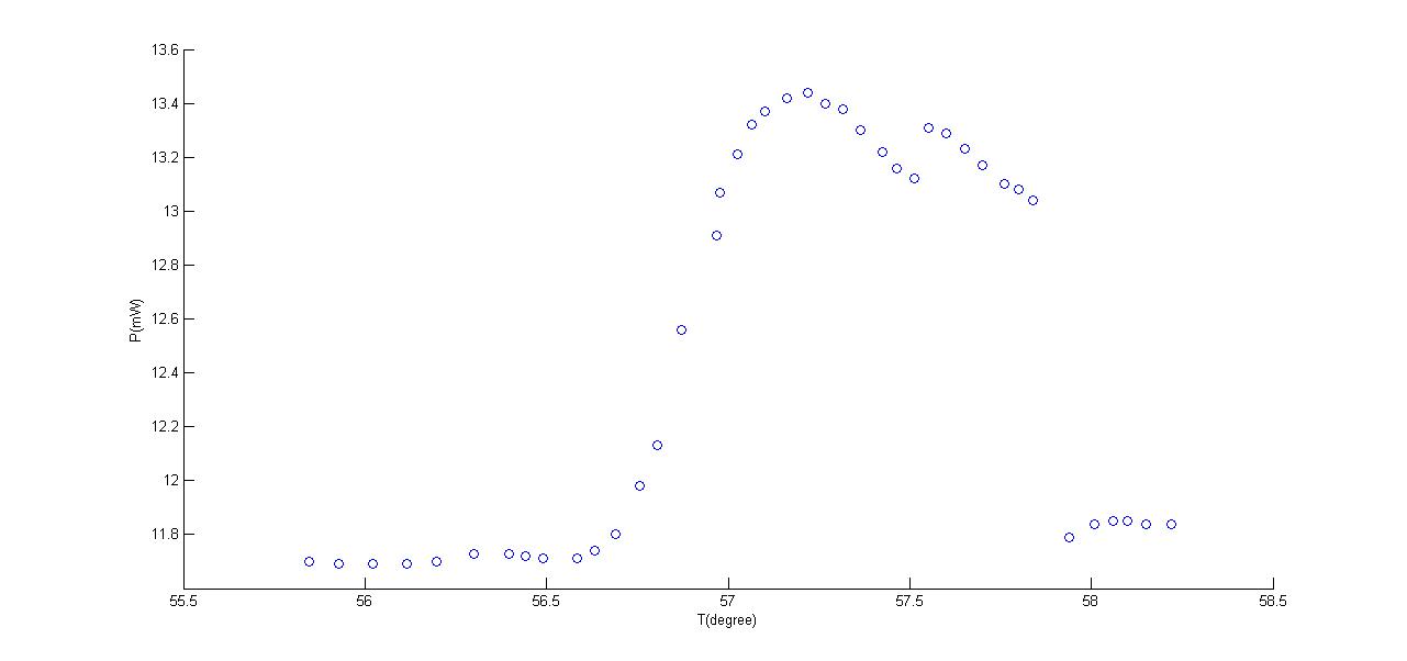
Since directly we cannot see the temperature, the peak of the figure has the resistance of 3.265 kiloohm.
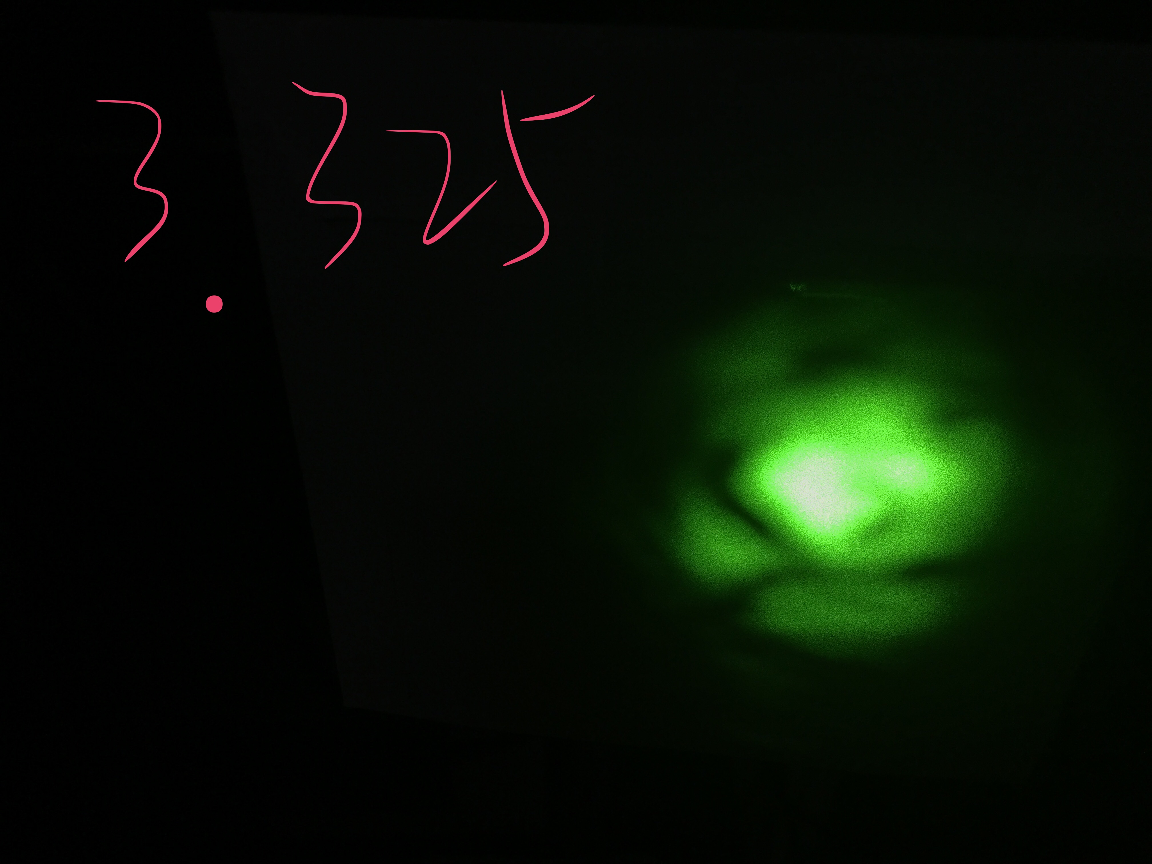
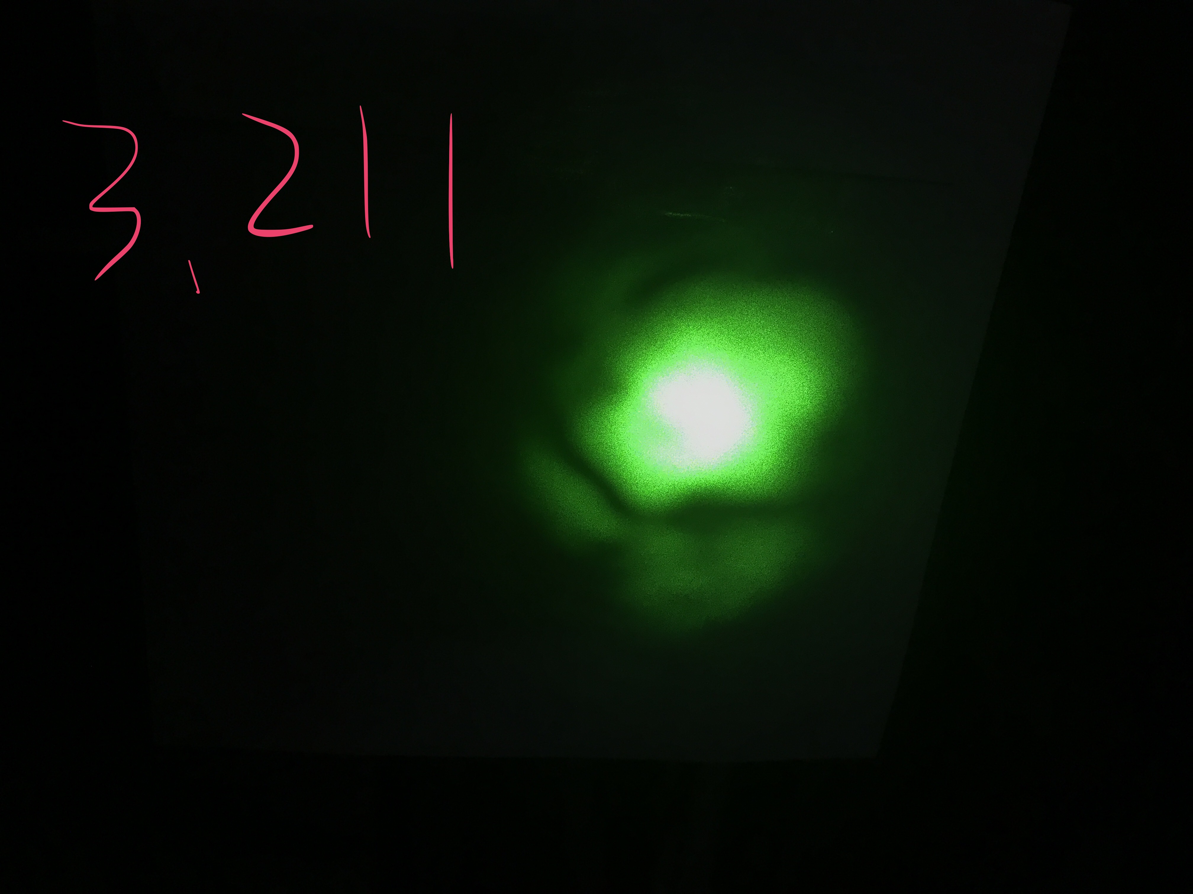
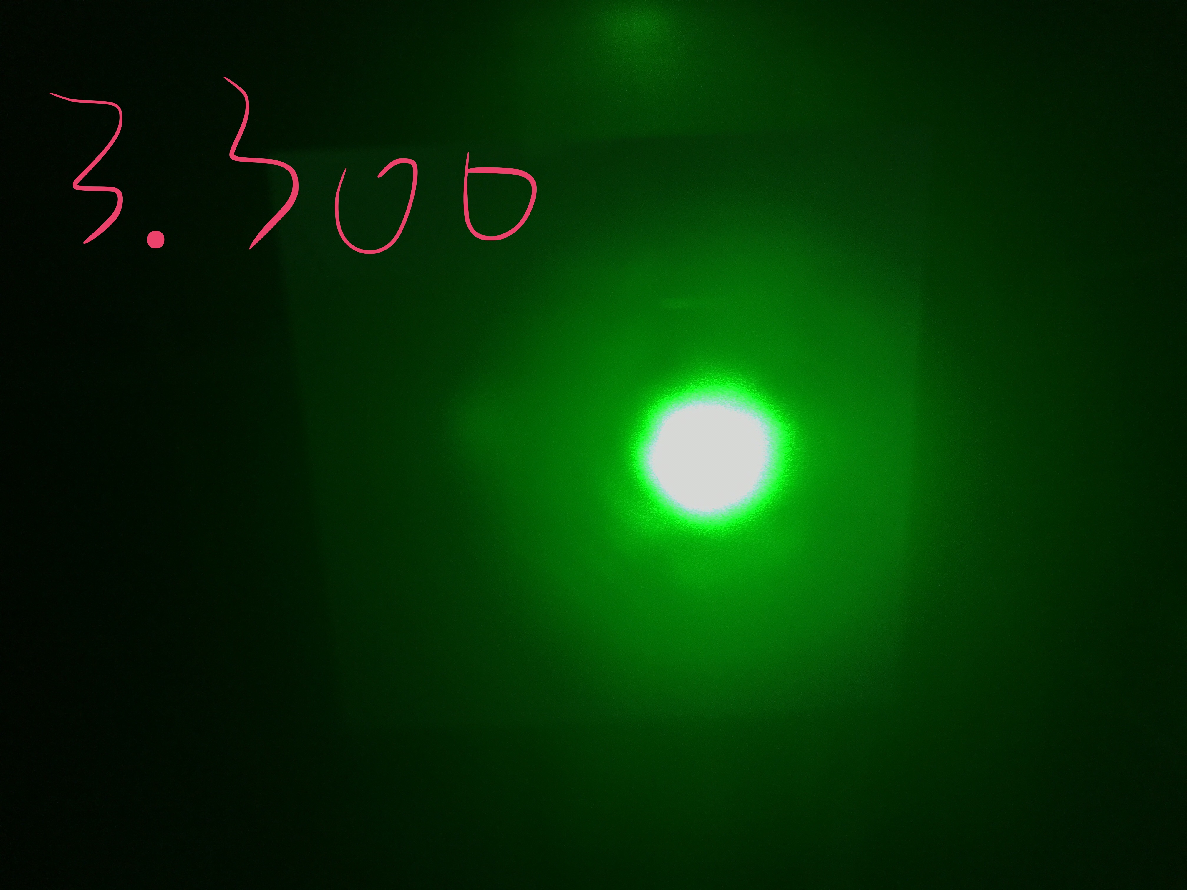
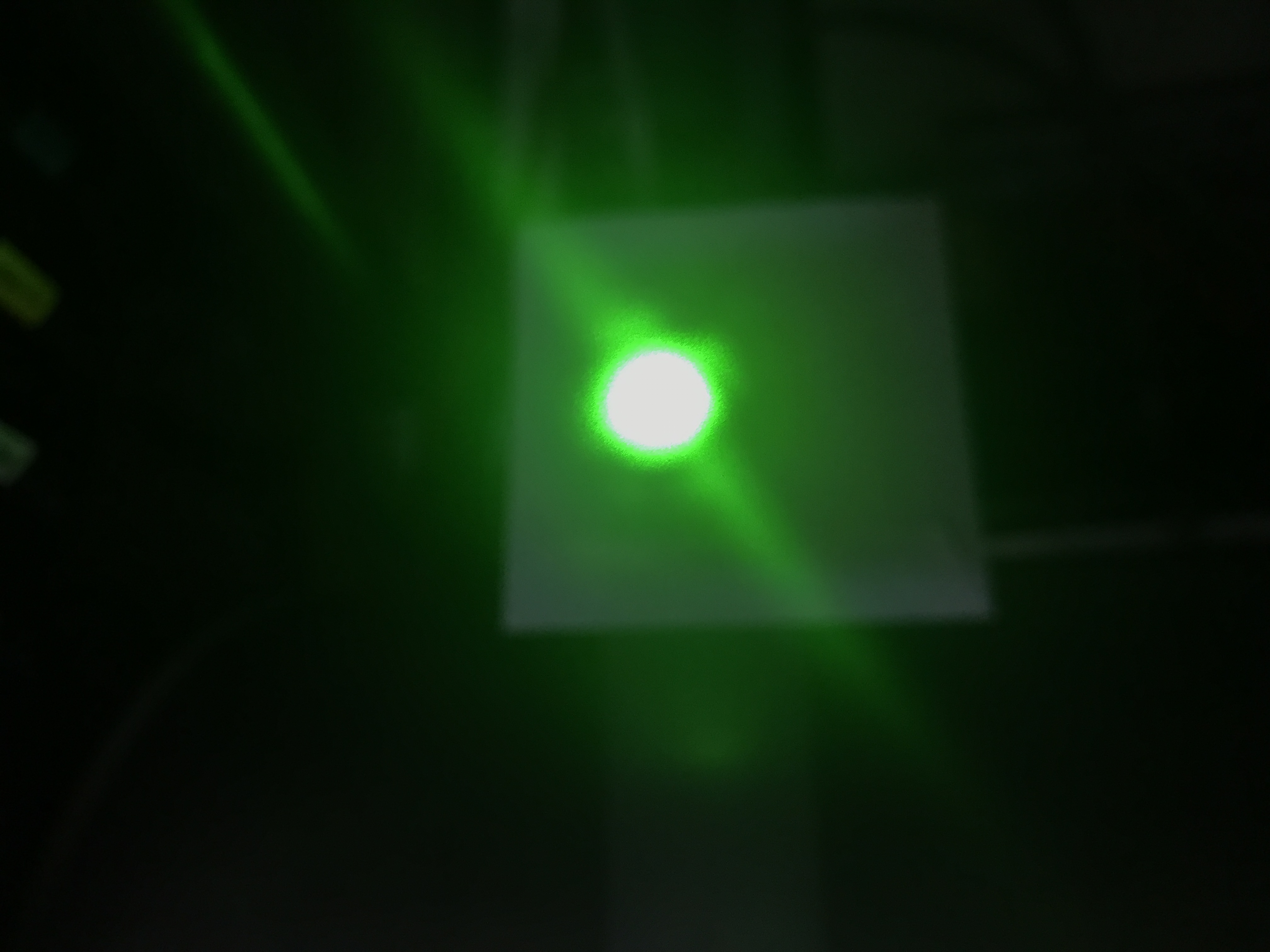
And in the following three pictures, the beam shape changes while the temperature change.
The second and the third pictures show that the beam start to get strange, inside this range, the beam basically is a spot, but as the temperature goes away from the maximum, there are more things around the spot.
We did some test today find out the reason why there is asymmetric of the resonance peak.
1.Set the temperature back to near room temperature, when there is no green light produced. In this way, we get rid of the effect of the green beam. But the asymmetric does not change much.
2. Change the laser crystal temperature, still nothing change.
We did not find the reason for the asymmetric, and also from the error signal, it seems there is some offset, but did not very clear where it comes from. I will change the PD to the one more sensitive to the infrared and with the 15MHz tuned.
Out of the resonance is very close to zero as it should. So there is no large electronic offset.
On one side of the resonance the signal is positive and looks relatively normal.
But on the other side of the resonance it's only slightly negative and when the cavity is at
resonance the signal is positive. A picture would have helped this explanation.
- When the cavity is at resonance we measured about 65 mW on the green beam coming
from the SHG and transmitted through the dichroich mirror. It would be nice to see how much
IR power we are injecting into the SHG cavity. It would also be interesting to see how much
green light is not transmitted by the dichroic mirror to have a full picture.
I attach some slides where I have summarized the work done to prepare the filter cavity servo.
In the second attachement there is a computation of the optical gain of the cavity.

Before when we tried to get the relationship between the temperature(resistance) and the green beam power we did not install the miniscope ,so that's maybe the reason why now we need to change the temperature a little bit to get better phase matching.
I will take some data points to get the exact new best temperature.
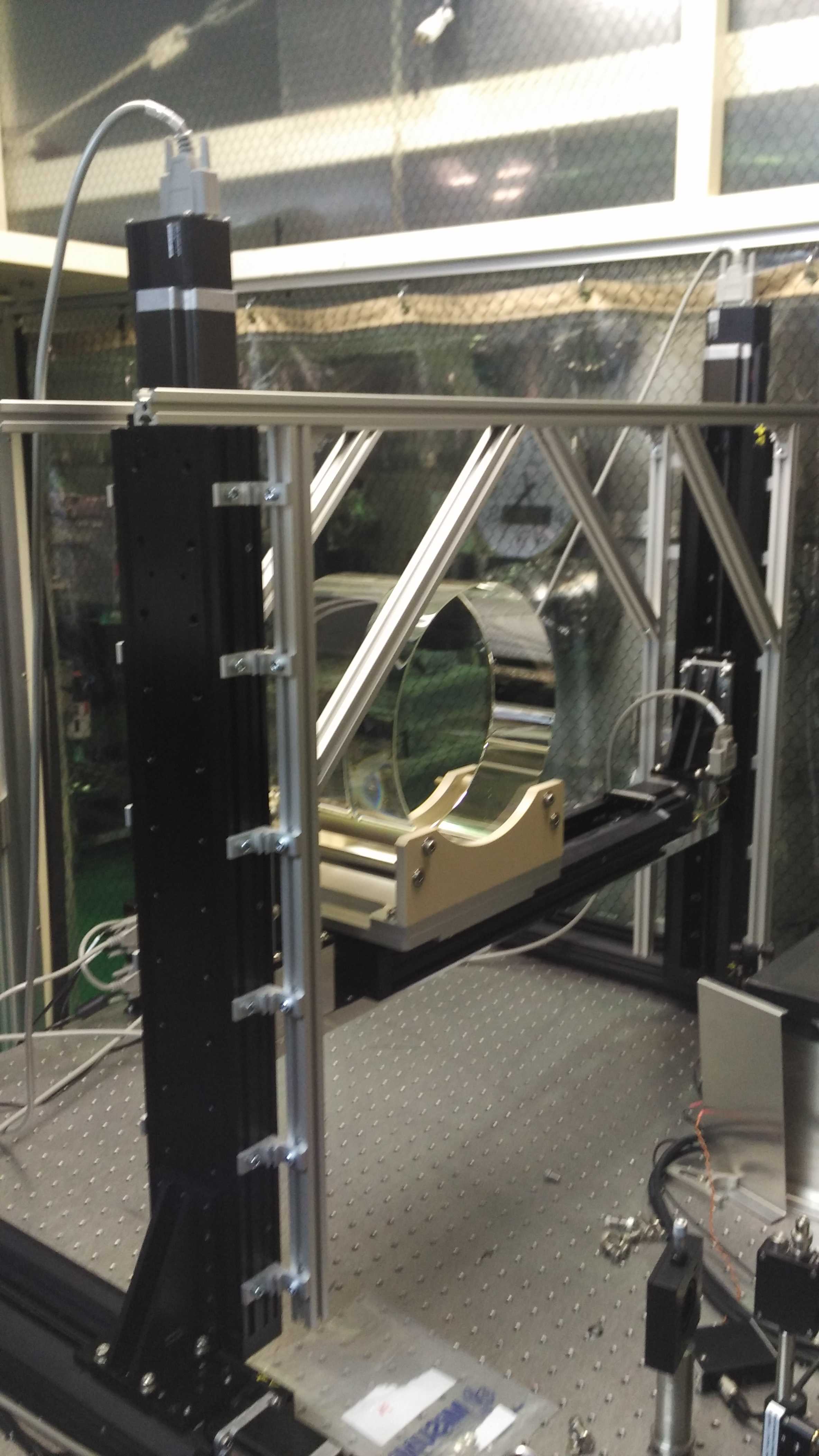
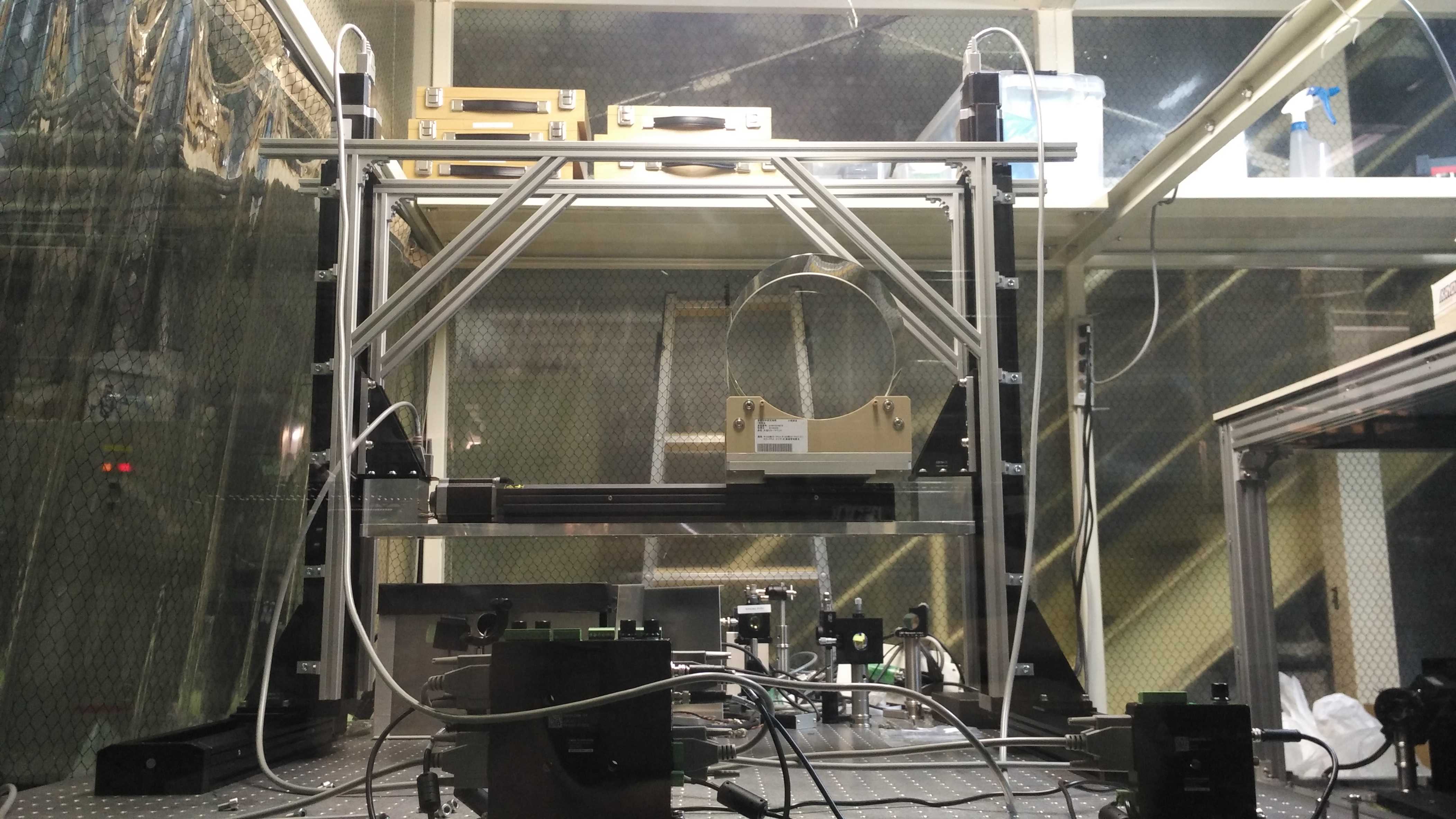
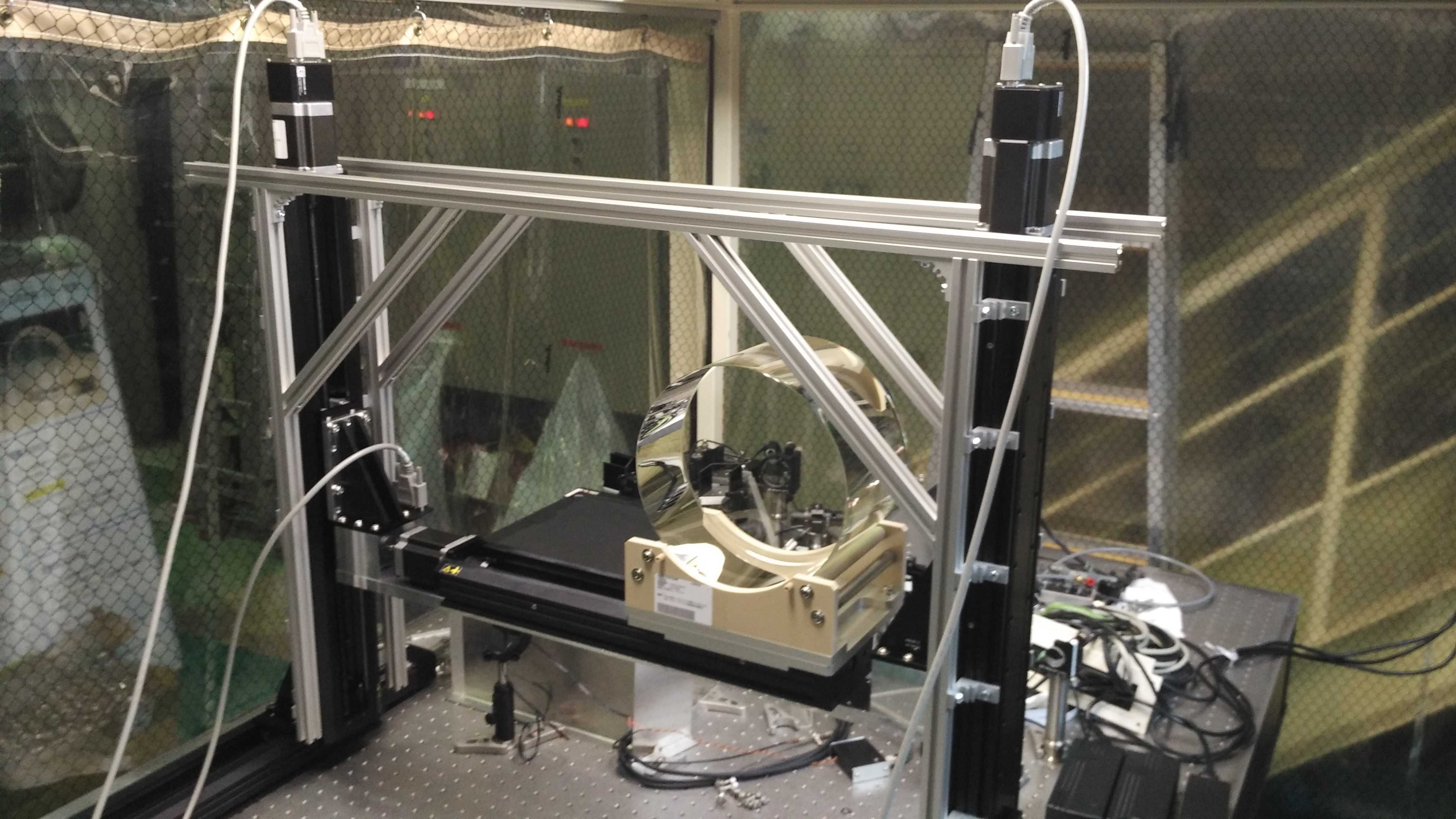
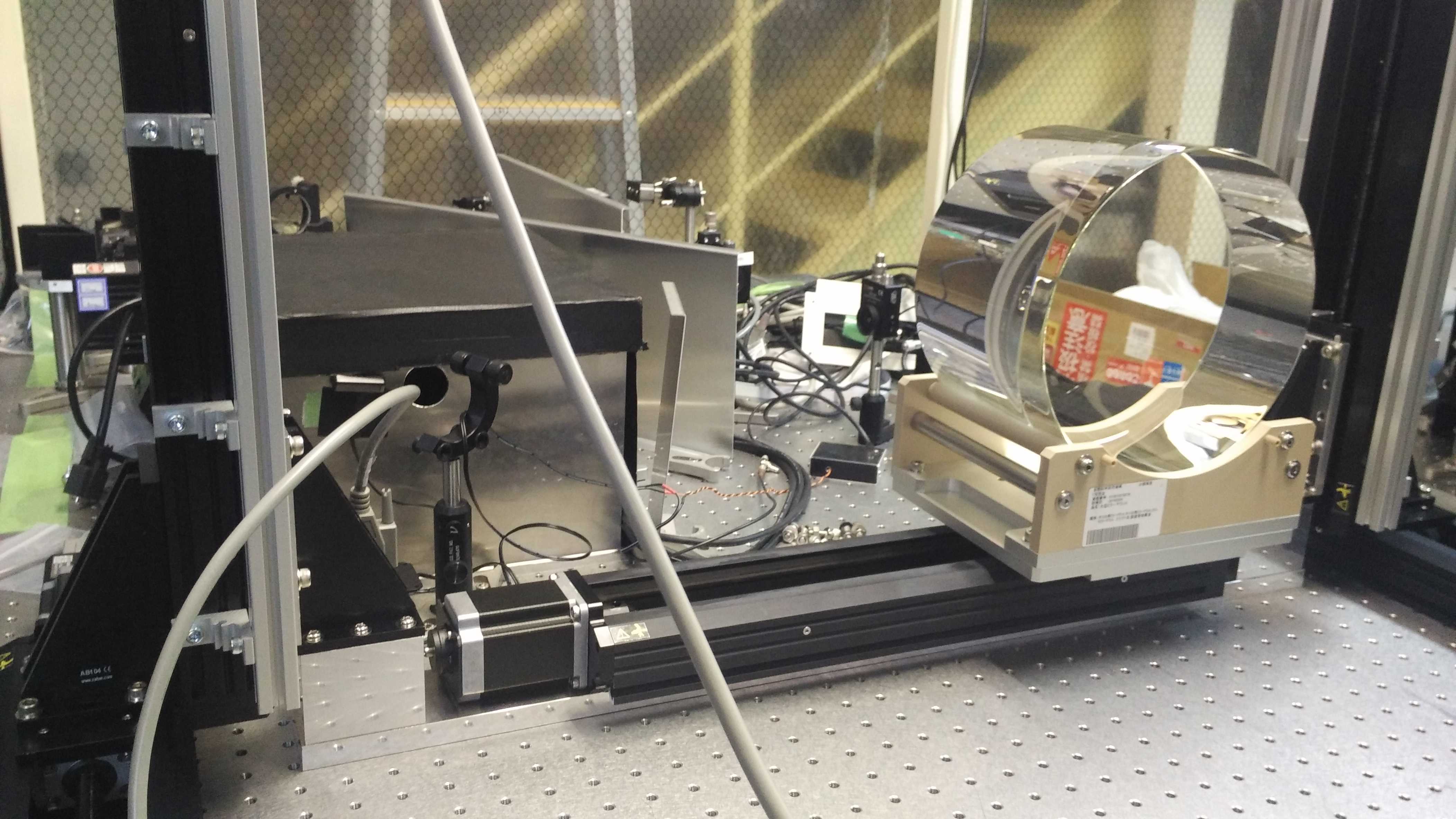
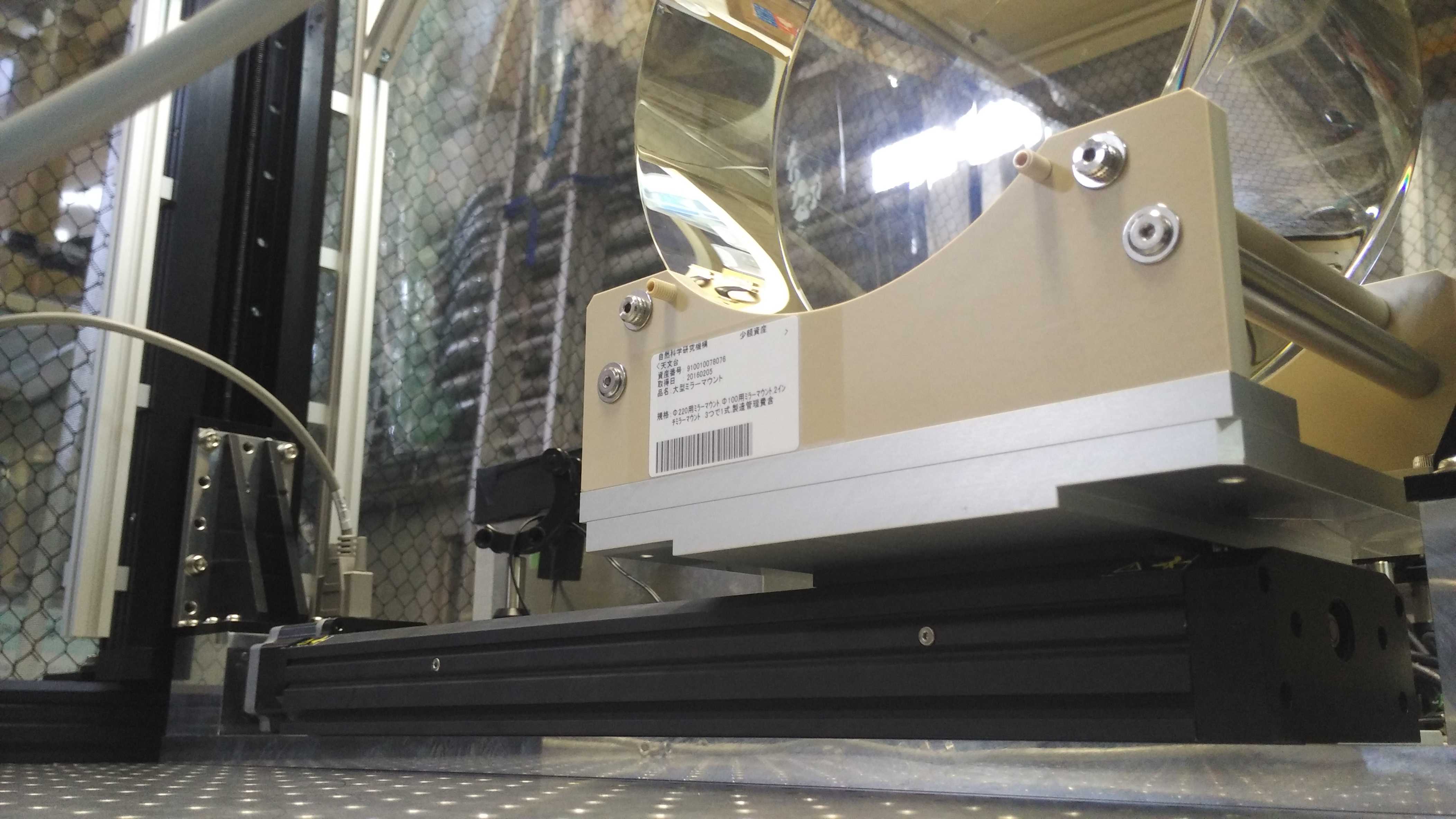
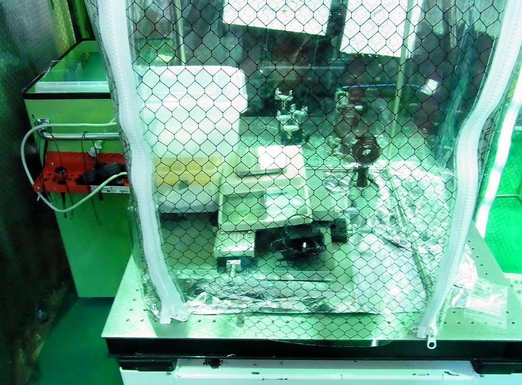
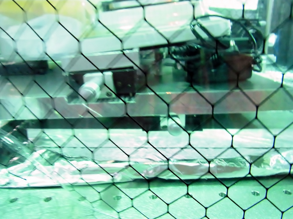
I got the parts I draw (elog entry 359) from ATC machining shop. Hirata-san washed them and I assembled the translation stage putting the parts to make the mirror height as low as possible.
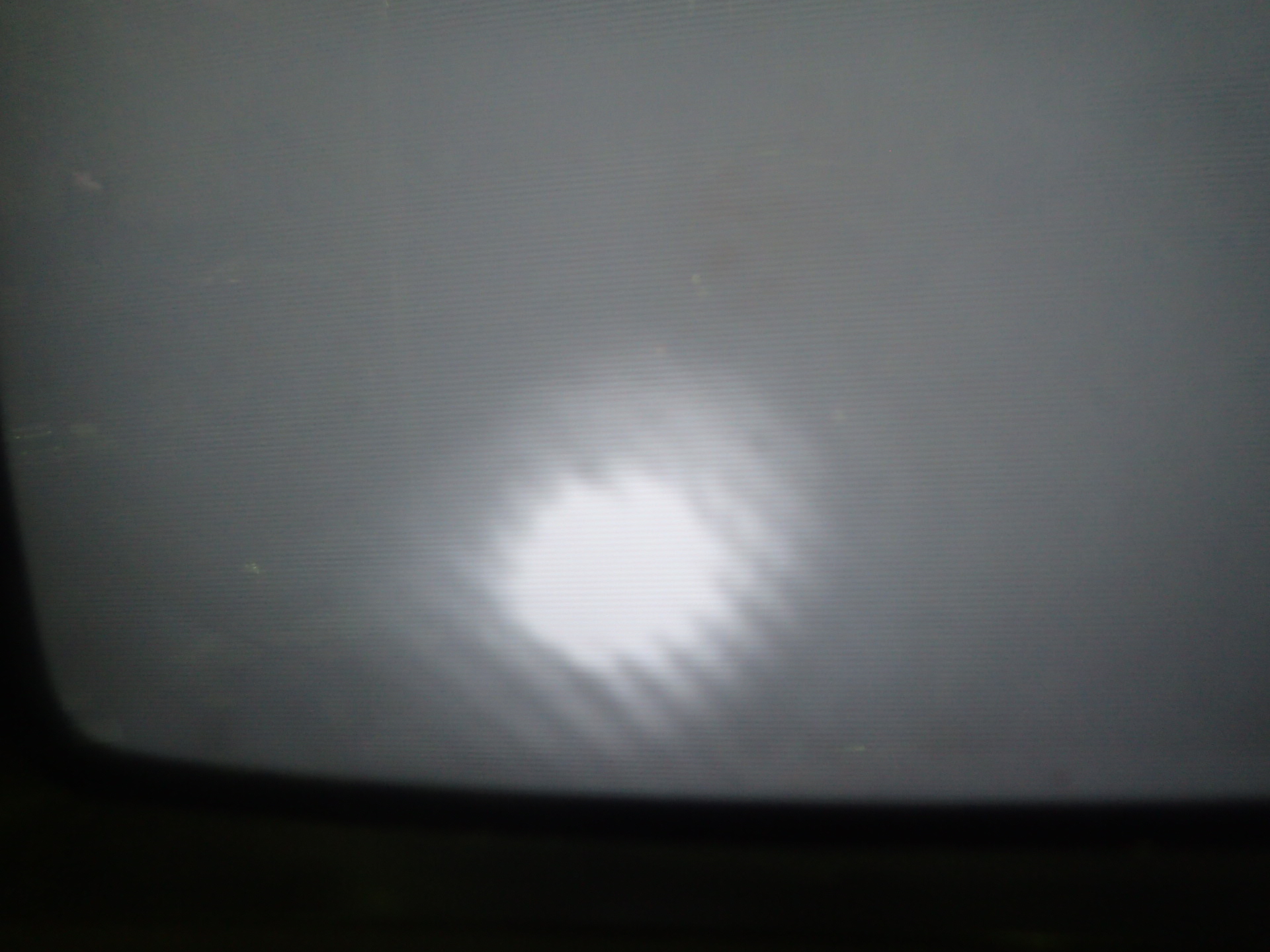
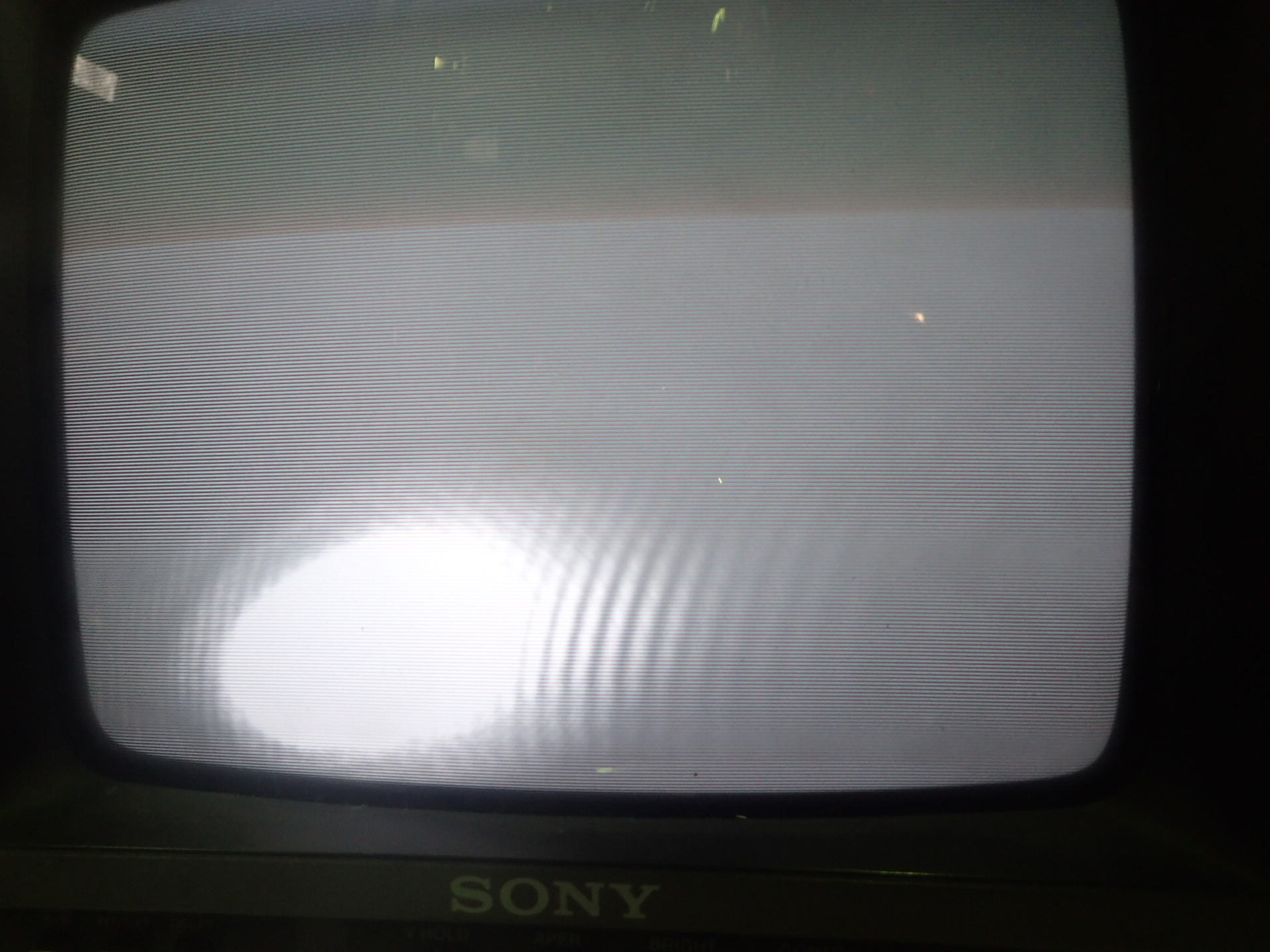
The first picture is set to check the beam in front of the dichoric mirror, and the second picture is what I got. It seems a really normal beam.
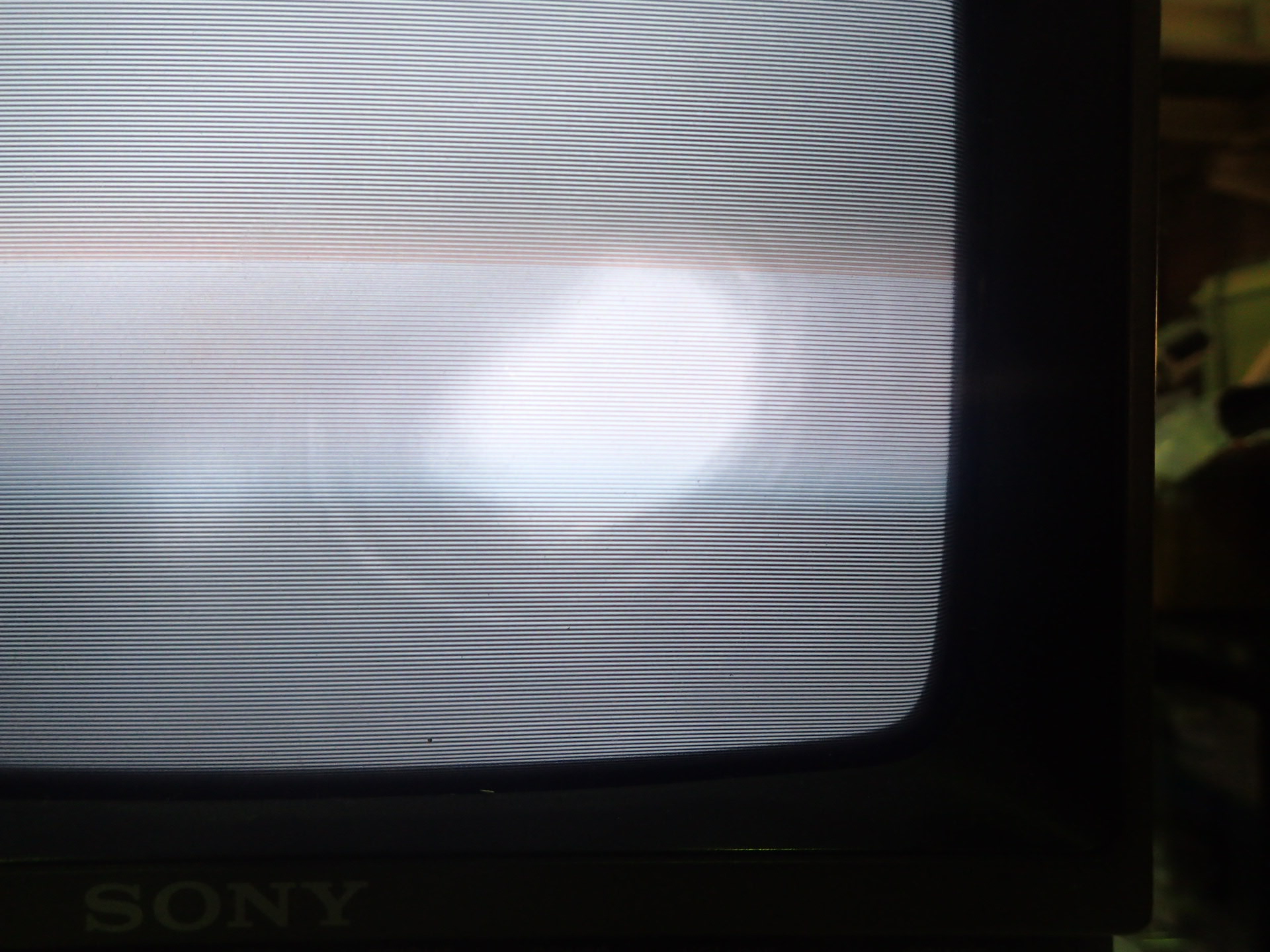
The third picture is set to check before the cavity, since I tried many different ways but cannot put another mirror in the middle of the dichoric mirror and the cavity without moving them, so I used the filter to reflect the beam. The fourth is what I got, it does not look like a round one.
So I change the mirror in first picture to filter to see if it is the reason of beam shape change, and I got the fifth picture.After checking the infrared beam many many times, I think the strange green beam probably not caused by the infrared beam.
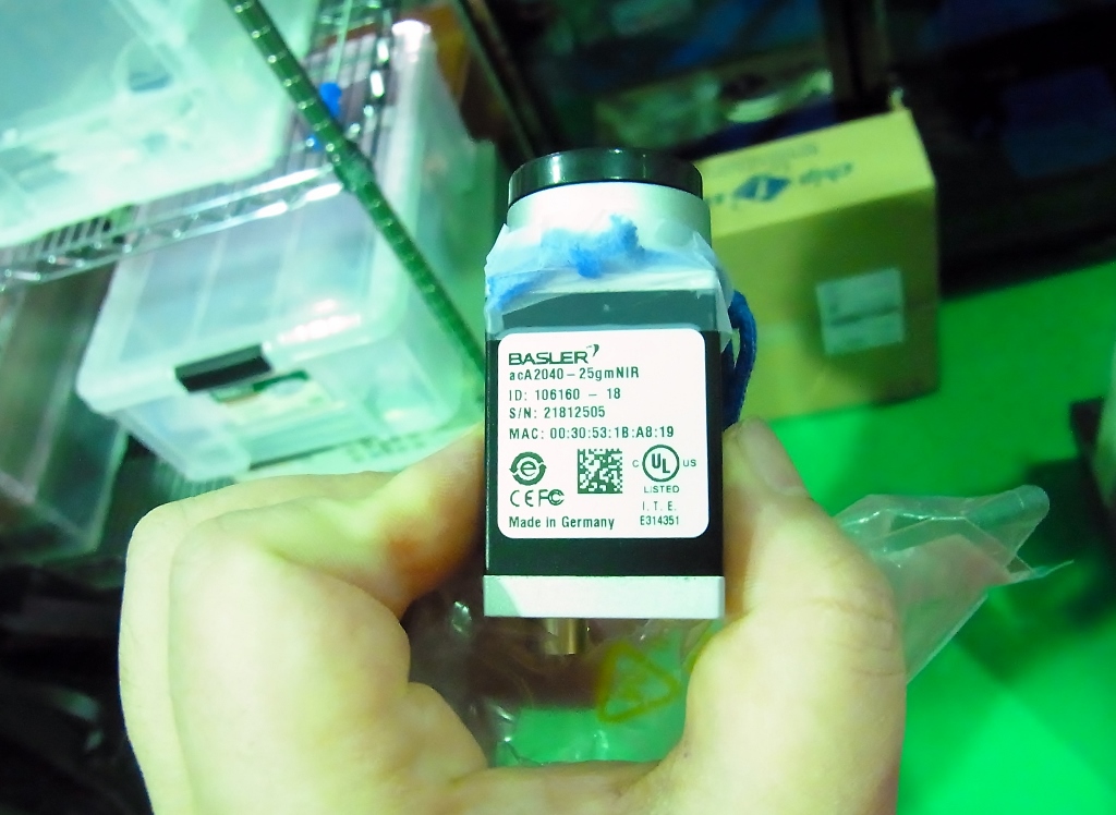
I bought a GigE camera.
http://www.baslerweb.com/en/products/cameras/area-scan-cameras/ace/aca2040-25gmnir
You can find information on KAGRA camera system.
http://gwdoc.icrr.u-tokyo.ac.jp/cgi-bin/private/DocDB/ShowDocument?docid=4237
To use this camera, we need
* Giga-bit Ethernet cable
* Power supply : http://www.baslerweb.com/en/products/accessories/ios-power/power-supply-12v-hrs-6pin
* PoE (Power over Ethernet) Injector: http://www2.elecom.co.jp/network/injector/lan-gsw01es1/
and
* Pylon software: http://www.baslerweb.com/en/support/downloads/software-downloads
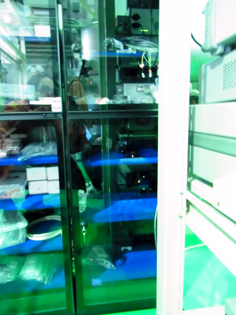
Together with Yuefan and Manuel,
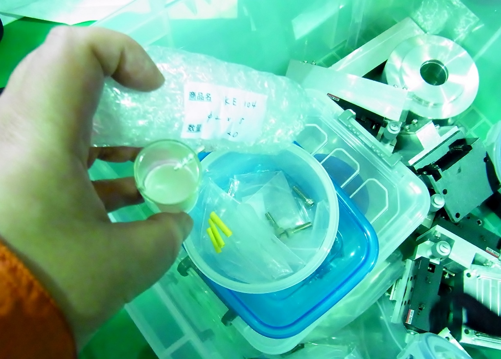
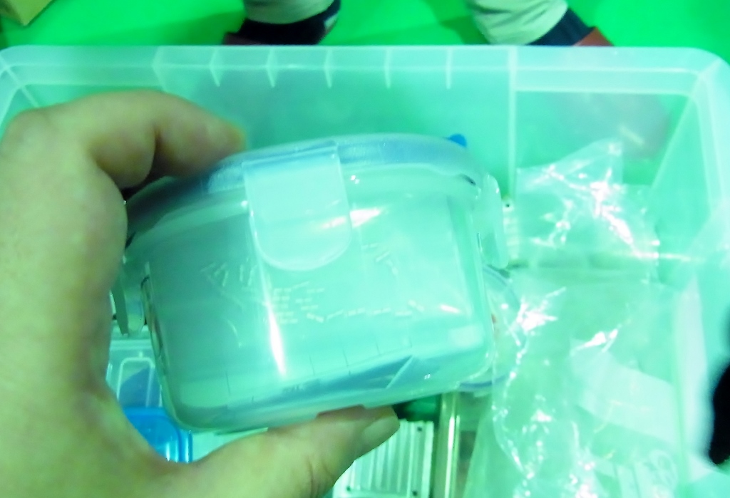
I confirmed that two mirror glueing jigs are storaged in small clean booth.
One is for 100mm diameter mirrror, and the other is for 150mm diameter mirror.
Related parts are packed into one large container box.
This large box is placed at large shelf. It is around the desiccator.
Inside this large box, magnets (phi 2mm x 10 mm) and stand-off (wire breaker)
are storaged in each small containers.
The former two positions, I just put a mirror to reflect the beam and look at it at far field, since the space before the cavity is narrow, so I used the filter to reflect the beam.
For now, the infrared beam looks normal even in far field, but I cannot manage to look at with the CCD.
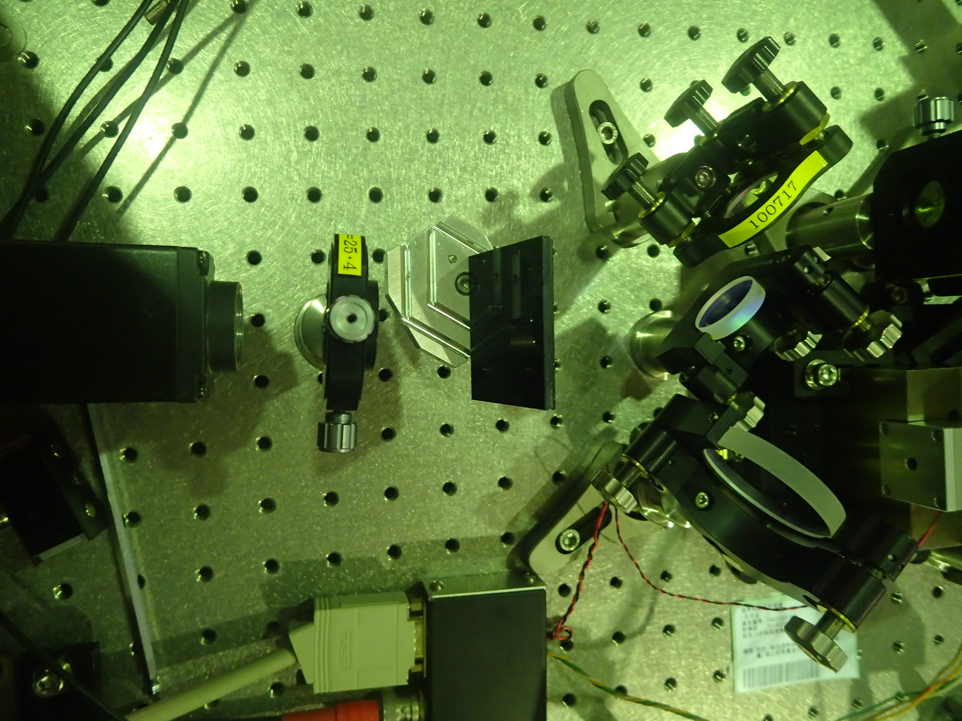
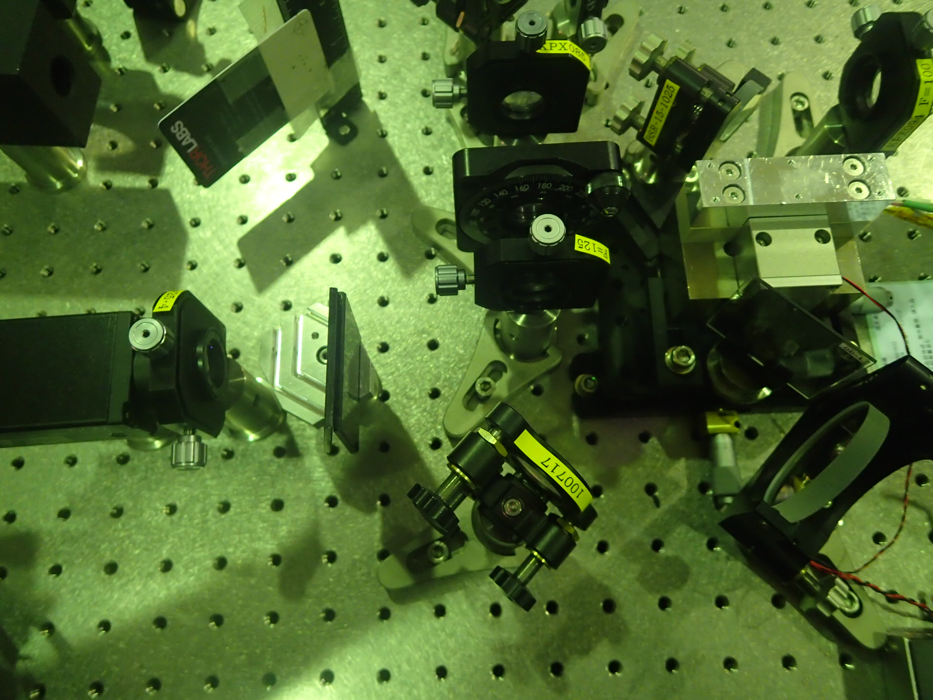
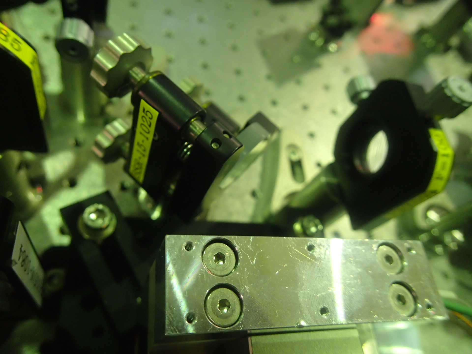
And I changed the BS mirror after the cavity to another dichoric mirror(CVI 1 inch one) as the picture shows, which reflect infrared and transmit green.
According to Raffaele's advice, I used the signal generator to send a sin wave at modulation frequency but with 100mV amplitude to the oscilloscope, and with a T shape lemo connector plug in and out the RF in port of the demodulation board to see the change of the amplitude. When the RF in port did not connect, the amplitude showed on the oscilloscope is A, when the RF in port plug in, it changes to nearly a quarter of A.
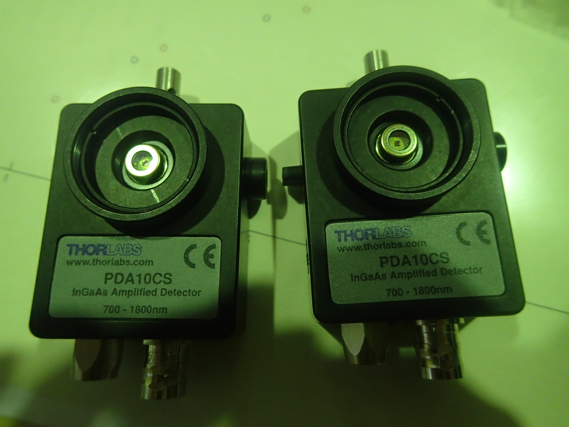
And Manuel found these two PD while clean-up, it can be used in infrared.
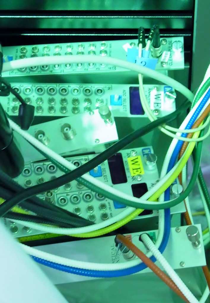
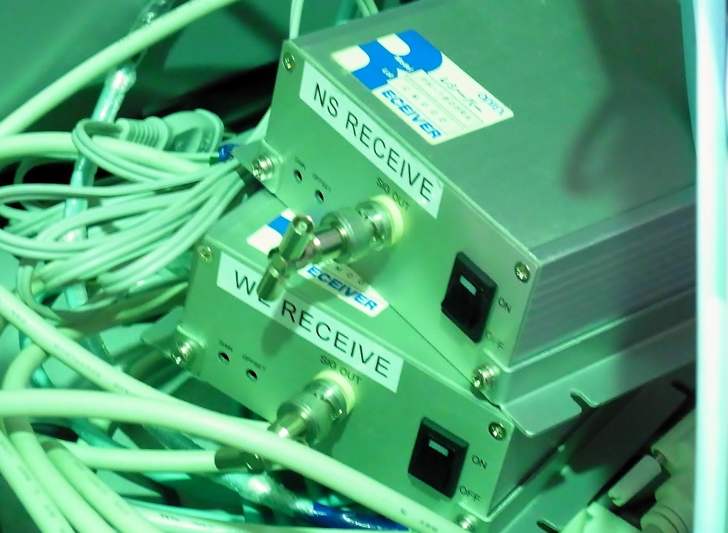
There is two systems.
When we replaced the system to new one, I wrote the attached report.
New signal transfer system has low latency for monitoring the transmitted light of 300 meter FP cavity.
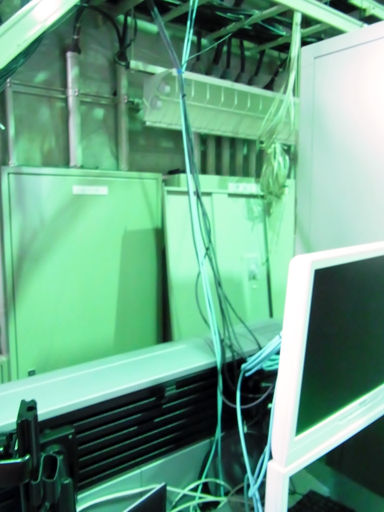
Today I found two receiver modules in the center-room.
Both of old and new system modules are placed behind a LCD monitor for digital control system of optical lever.
Maybe signal sender modules can be found at both end rooms.
Because optical cables are unplugged for new system, please check the cable assignments
by sending some signal from the end-room.
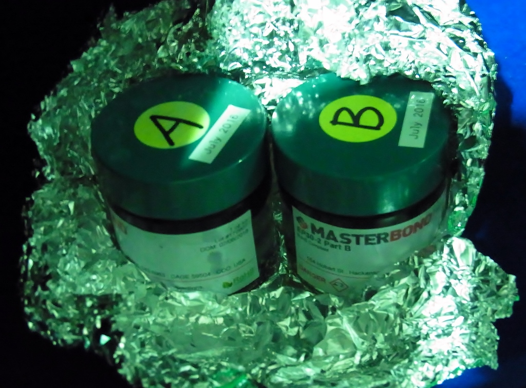
I confirmed that a set of MasterBond EP30-2 is storaged in desiccator (dehumidified storage shelf).
I started repairing the scatterometer in the JASMINE lab today.
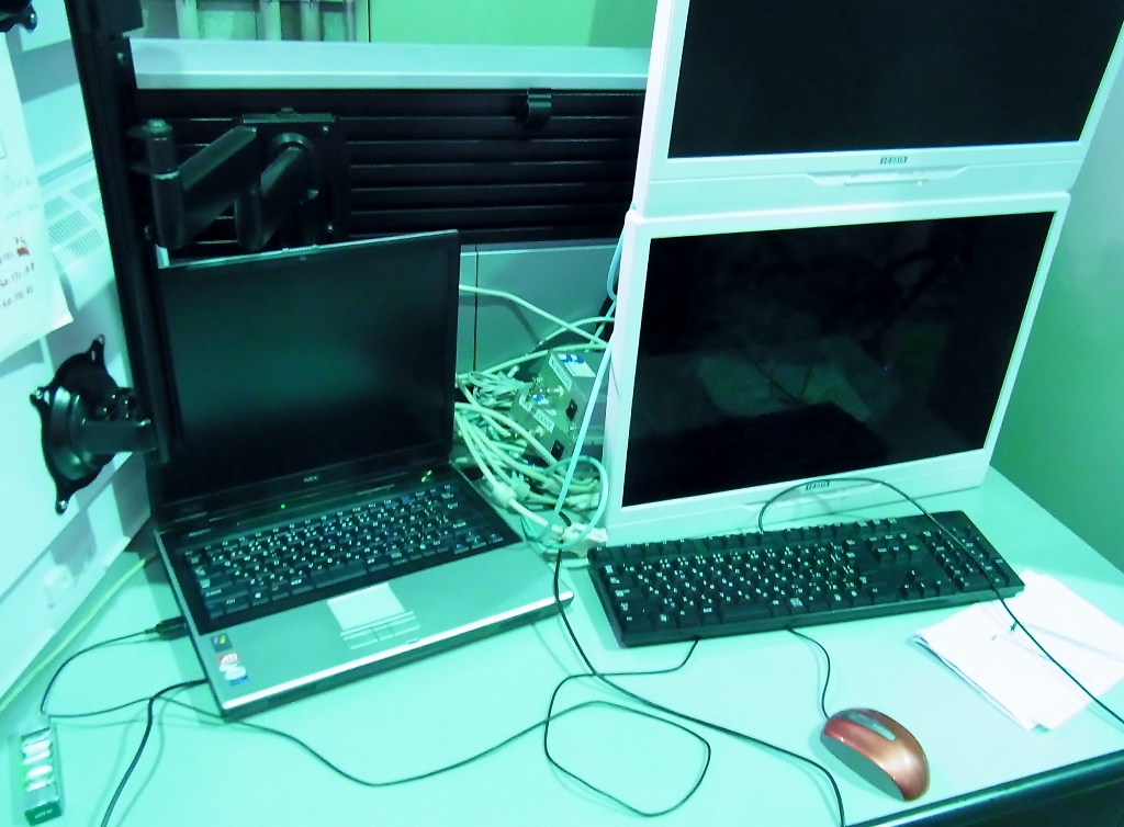
Before doing the actual setup of the new laser, I cleaned up the desk and put the PC, the lock-in, and the motor-power supply on the desk beside the optical table. This gives now much more space to anybody working there.
I also tested the switch-box that has been build by Tanioka-san with the new laser. So far, everything works well.
I added some aluminum beams, bought from Misumi company, to increase the rigidity of the translation stage
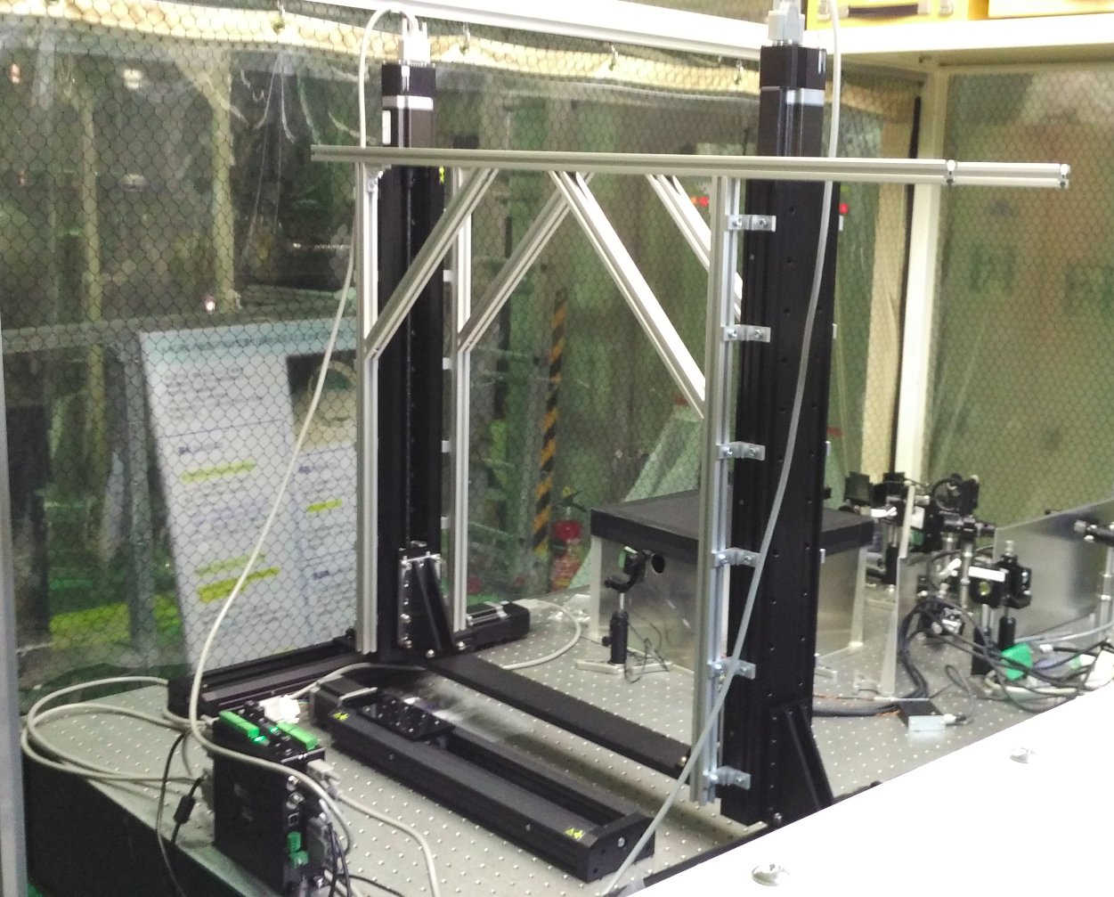
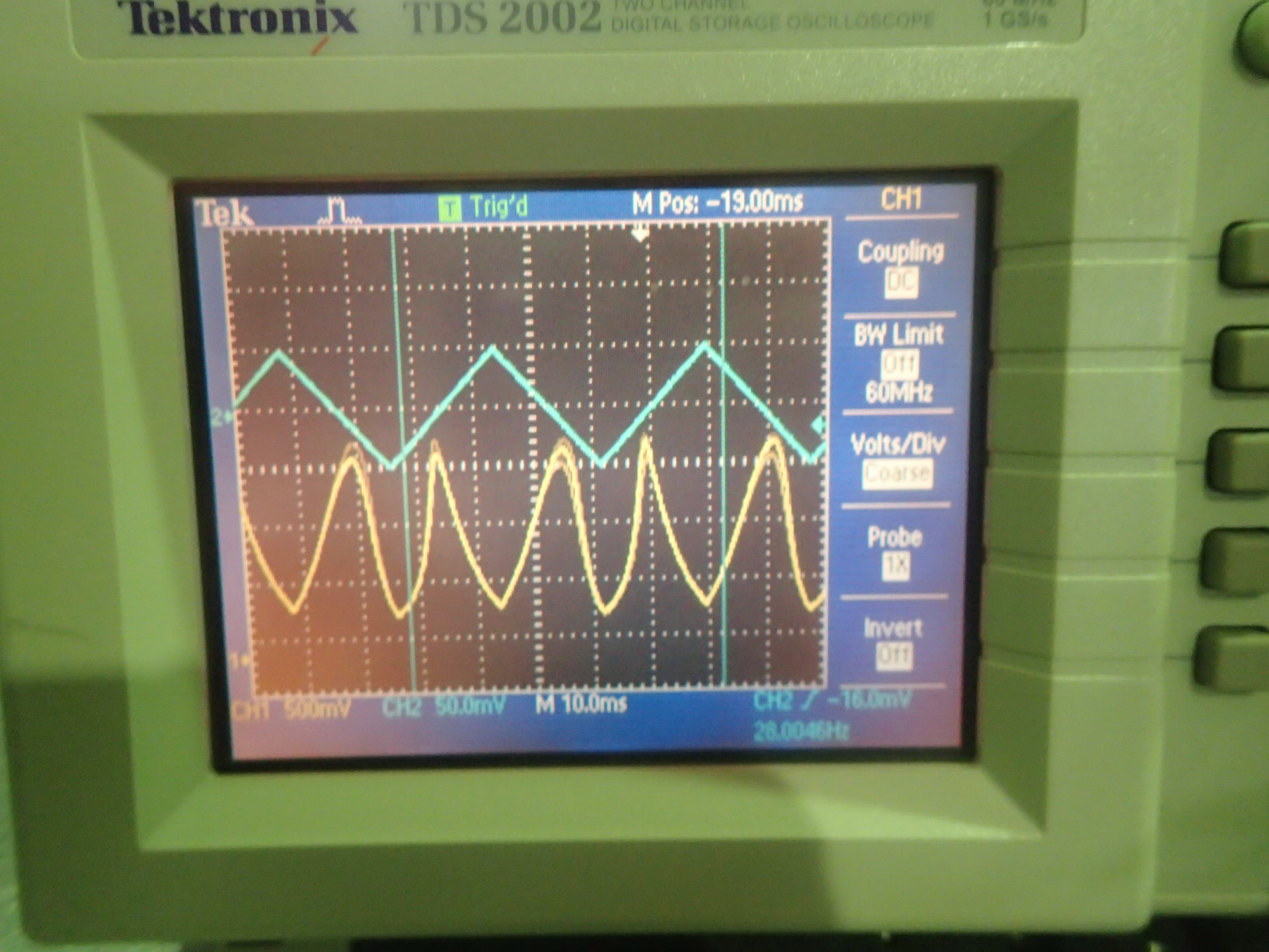
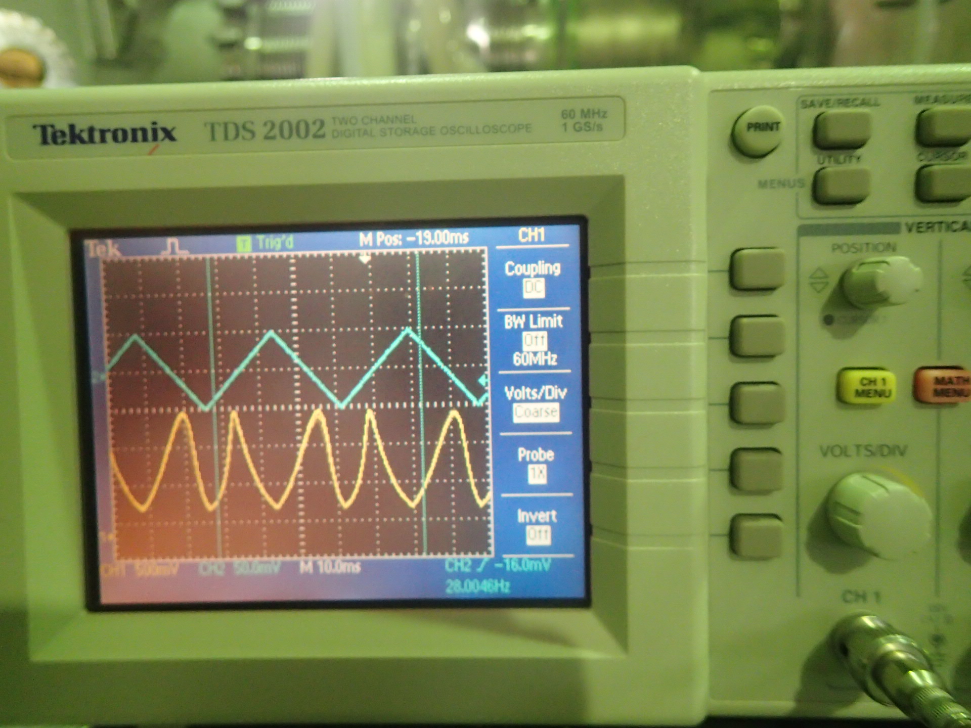
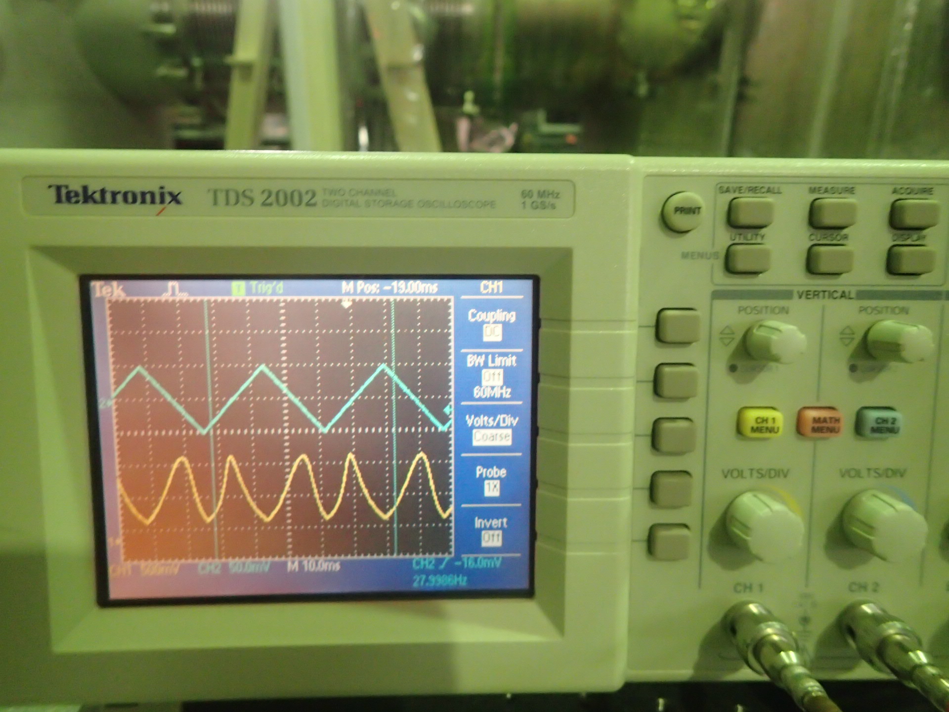
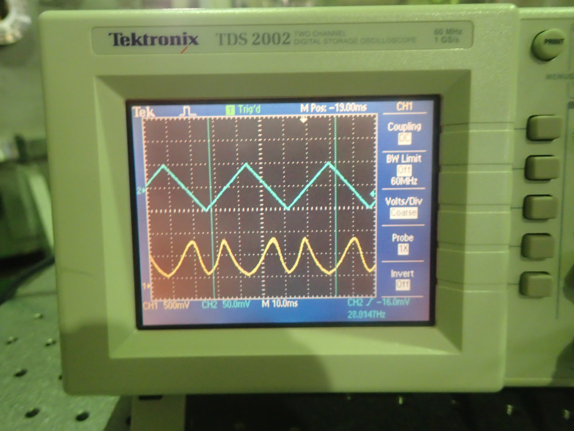
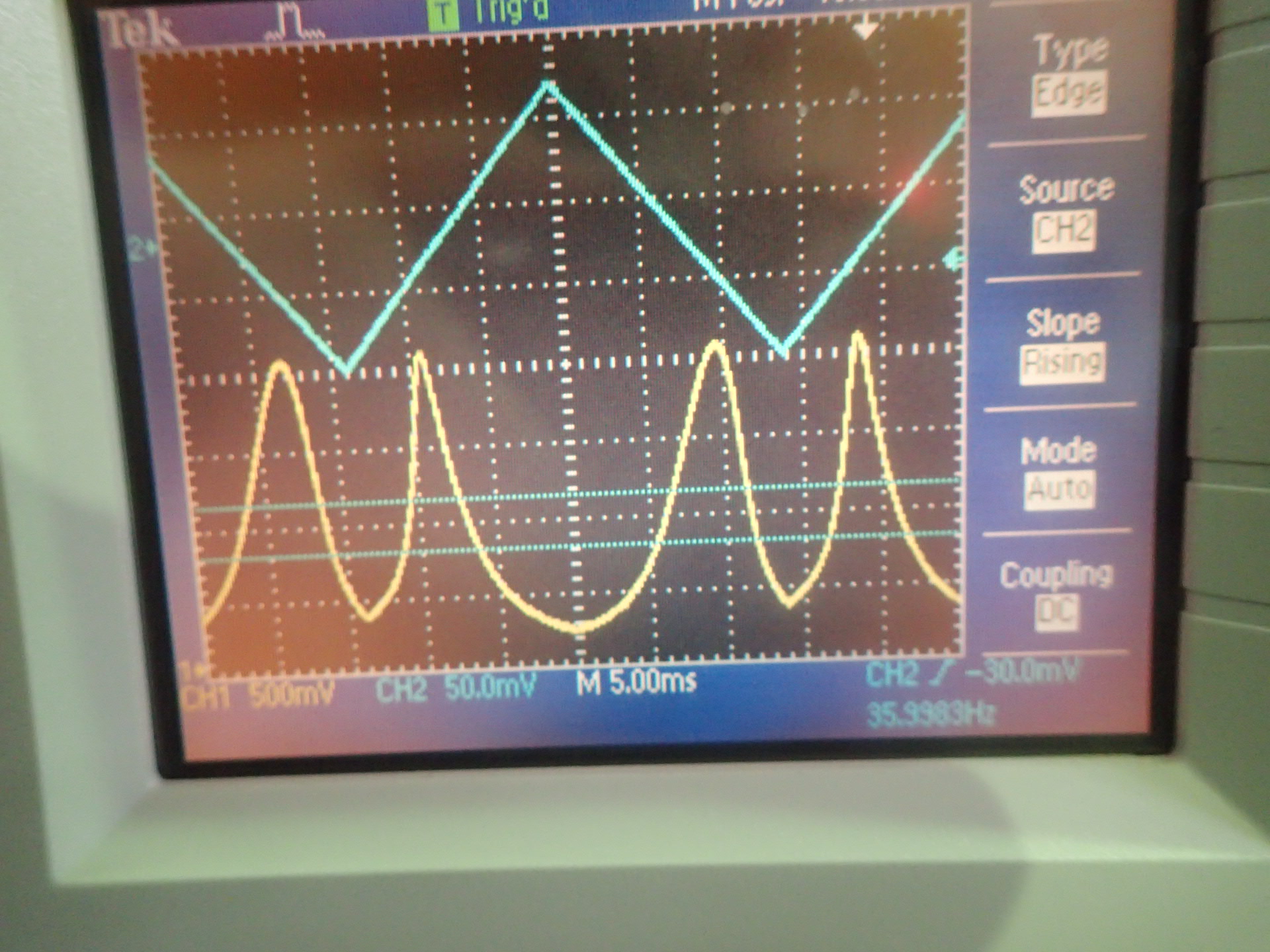
For the second picture, I tried to scan the cavity with pretty small amplitude triangle wave, and then change the PZT driver by hand to get near to the resonance.
From the picture, there are two problems:
The first one is the what I described before, the slopes from two side of the peak is different, take the first peak as an example, the reduce process is faster than the increase part.
The second is that the two different peaks are actually the same mode but they did not look the same. I discussed with Manuel and we thought it maybe because of the hysteresis, there are some loss in the PZT.
1.The power of the TEM00 transmission drops suddenly
When we try to scan the cavity by changing the output voltage of PZT driver by hands slowly, we can observe the slowly increasing part of the TEM00 power both in the PD and CCD, but then when it reaches its maximum(or near) it drops suddenly. On the oscilloscope connected to the PD, we can see that the power suddenly drop from several tens of mV to several mV, and from the CCD, the diameter of the beam and also the brightness suddenly get smaller.
When I try to lock the cavity, I did as what I will describe below, which I am not sure it's the right way or not. The power of the TEM00 will change from weak to strong and go back to weak when I scan the cavity, which means there is a range of the voltage that gives to the PZT, like from 15V to 17V, I tried to lock the cavity at different voltage. If I chose to lock the cavity at the maximum power, the lock will last for less than 5 mins, and from the CCD I can see it get weaker and move to next modes. And if I locked the cavity at the range where the power is slowly increasing, the lock will last longer, like more than one hour, but the power still slowly increase to the maximum and start to reduce, finally it moves to the same 'next' modes as in last situation. And if I start in the 'suddenly drop' range, it seems much more stable then the other situations, I wait for more than one hour, the power increase to some point at the first beginning then it stops there and does not have any obvious change after. I am not very clear about what this means, and I am also not sure about this result can be repeated since I tried the last situation only once. So maybe if it has some meaning,I can try to do it tomorrow again.
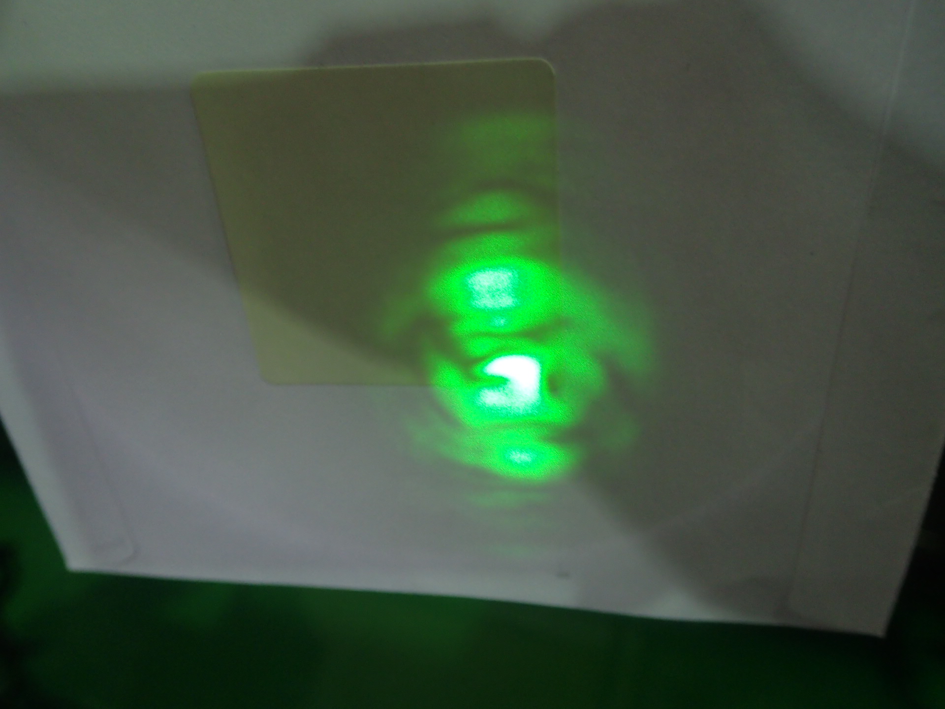
2.The strange shape of the green beam
If we look at the green beam when the cavity is locked(the green is much more powerful and easy to see the detail)and the temperature is at the 'good' temperature, the beam is not a spot, there are many irregular dark lines in it which cut the green like into many strange shape pieces. At the beginning of this week, when we see the green light under room temperature, it almost a spot with a circle which is caused by the Laguerre mode. But now even when we turn the temperature back to the room temperature, it is not as good as what we saw before, but because it's very weak so we can not see it very clearly what exactly the pattern is.
3.The TEM00 is 20 times less in cavity-locking compare to mode-matching-finding and the error signal is only several mV
In my Tuesday logbook entry I gave the picture how I lock the cavity, the PD is connected to the 'RF' port of the demodulation board and also the CH1 of oscilloscope. Also in this picture, from the small picture of the oscilloscope screen,(the yellow is from the PD), it shows that the magnitude of TEM00 (the highest peak of the CH1) is about 50mV. But when we did the mode matching(CH1: PD, CH2: the triangle wave), the TEM00 is more than 1V. Then we found out if disconnect the demodulation board 'RF' port and the PD, the TEM00 goes back to it used to be (>1V). It may caused by the input resistance of the demodulation board,so I will check the PD output resistance and the demodulation board input resistance, to make sure this problem is caused by them or not.
4. The output voltage of the PZT driver does not change
When the loop is closed, if there is some fluctuation, then the feedback should work and the PZT driver will give out the voltage to push or pull the PZT, make it back to the resonance. And in my situation there is a screen on the PZT driver shows the output voltage of it, but it does not change during any lock process until now. My guess is the error signal is too small (couple of mV), the magnification of the PZT driver is 30 times, so even after the signal is amplified, it's couple of tens mV, which cannot show on the display of PZT driver whose digit limit is 0.1V.
I will check the following things later:
1. The properties of the PD and the demodulation board (resistances, the cutting frequency of low pass filter on the demodulation board)
2. Which PD we used in last locking with Matteo
3. The properties of the dichroic mirror, since it should be reflect infrared and transmit green, and now the reflection green beam is really powerful.
4. The exact power sent to the cavity when using the maximum output of the laser
5. The polarization we are using now
But it seems if I call the two modes near TEM00 as the previous mode and the next mode, the unlock always happened when the TEM00 move to the next mode, I think this means the PZT only let the mirror goes to one direction but I am not sure.
The other problems, the screen on the PZT driver shows the voltage it gives to the PZT, but during the lock process, it does not change. I think it is strange, because when there is fluctuation and the PZT will move to recover it, at this time,the number should change somehow.