NAOJ GW Elog Logbook 3.2

Aritomi and Yuhang
After the simulation, we implemented the filter cavity reflection telescope. It was quite strange that I moved a lot to match this beam into AMC. Maybe this is because of the injection is not well mode matched, so the reflection is also not in good shape. But anyway, we put this telescope and tried a lot to improve the matching.
The preliminary result is as the attached figures.
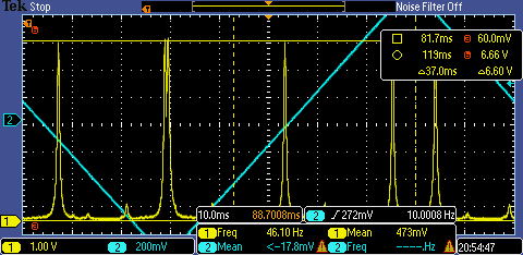
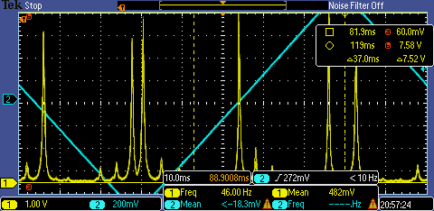
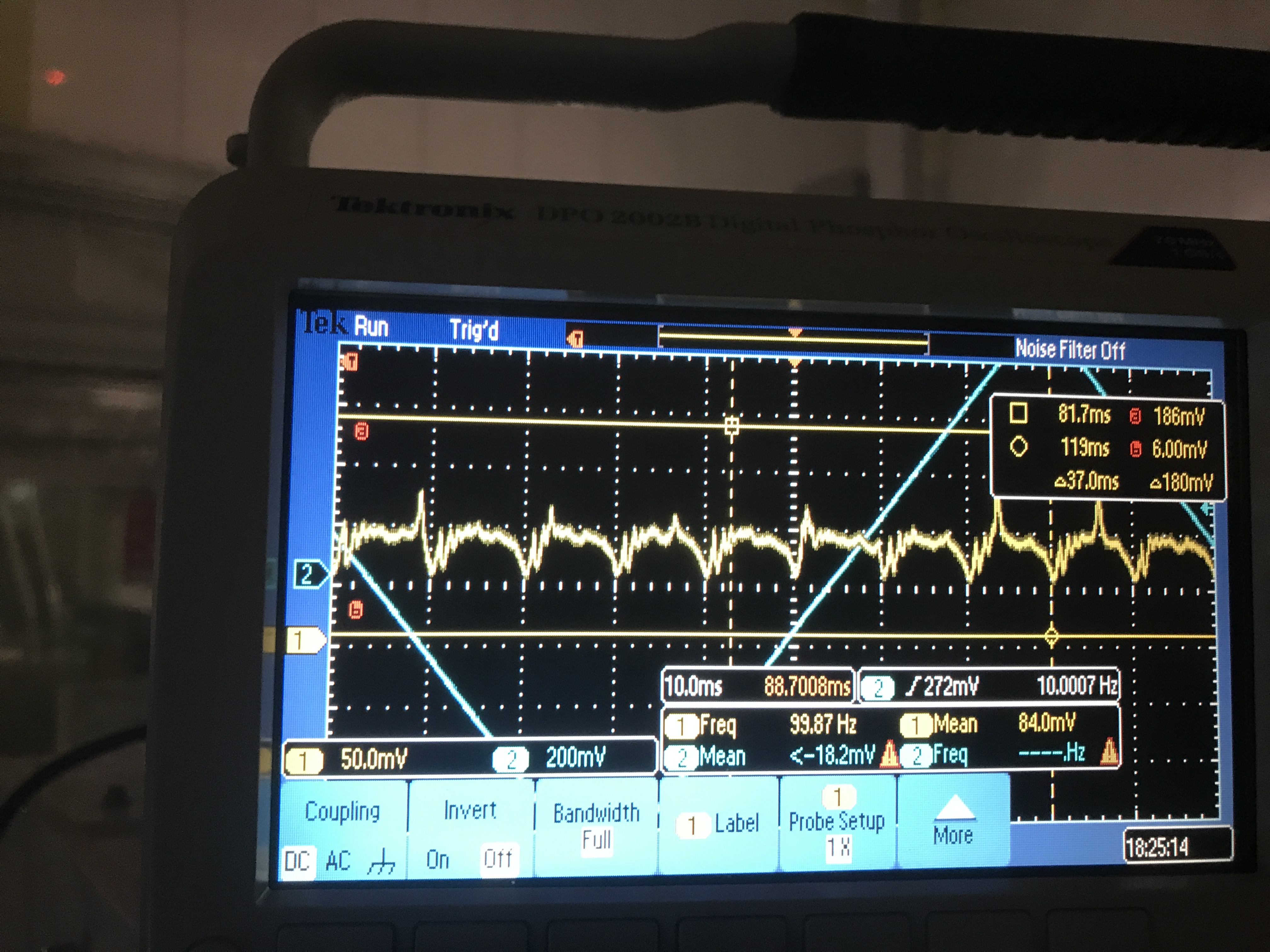
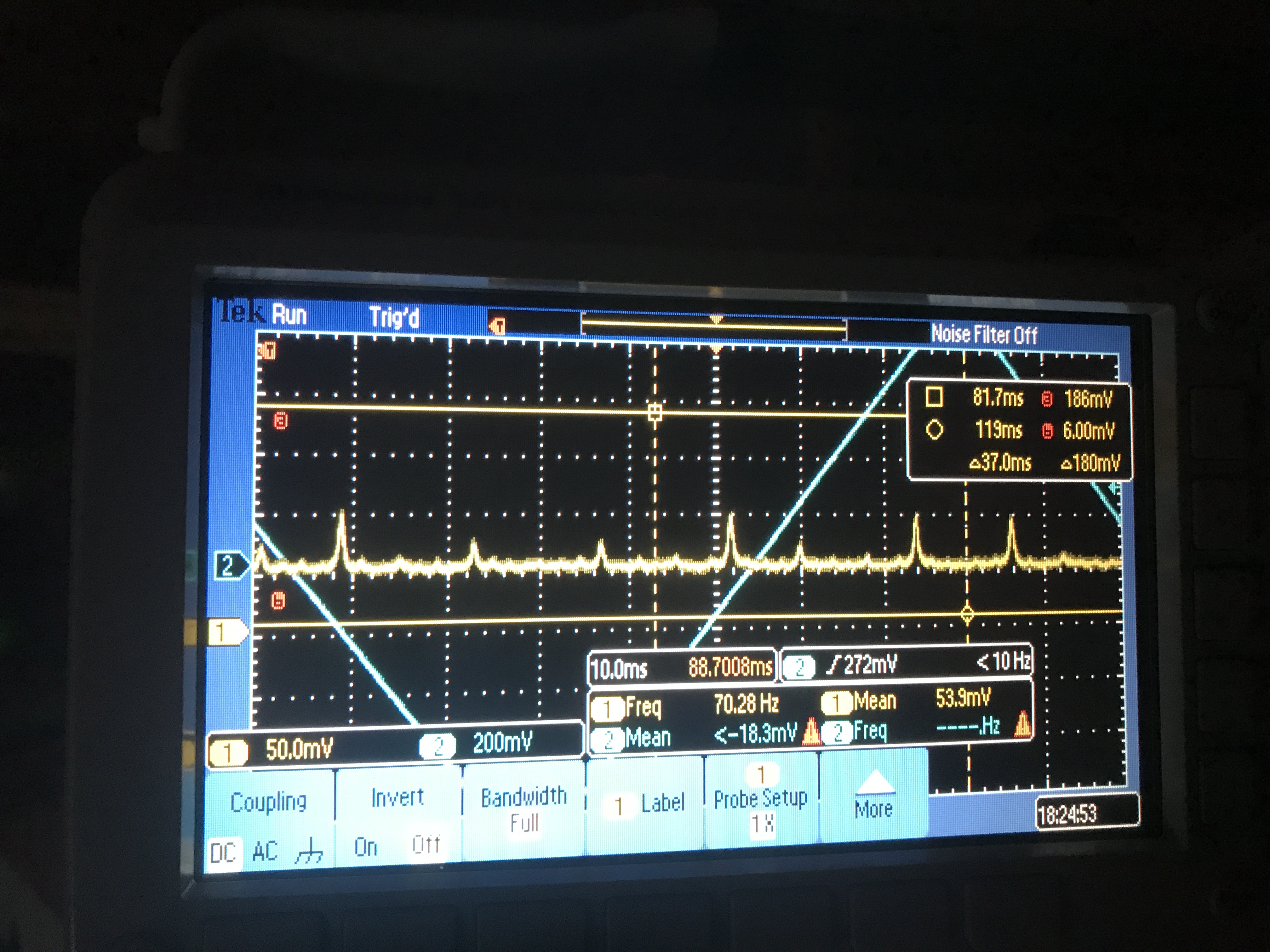
In the first attached figure, we could see there is a mode mismatch peak with a height of 540mV.
In the second attached figure, we could see there is a TEM00 with a height of 6.6V.
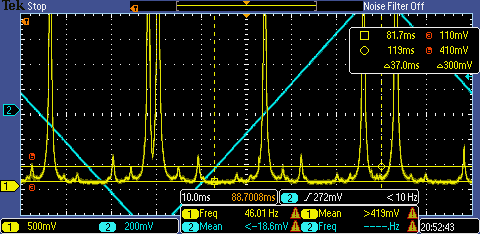
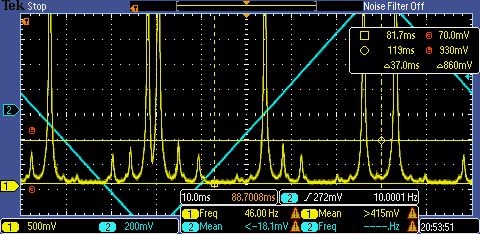
In the third and fourth figure, you can find a peak just beside the mode-mismatch peak. It changes height because of the beam jittering in pitch direction. And it can have height up to 860mV.
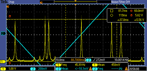
In the fifth and sixth figure, you can see the TEM00 peak can also change from 5.5V to 7.5V.
Conclusion:
1. We have roughly mode mistach now for filter cavity into AMC as ~7.5%.
2. Beam jittering brings misalignment of up to ~12%.
3. The estimation is not precise because the total reflected IR power also fluctuates. From the experience of green reflection, we see much more stable green reflection after using smaller focal length lens. Maybe we are having this beam clipping issue also for this measurement in IR reflection. We should check this tomorrow.
Found on 5th September, the beam was clipped!
As we talked in the meeting, I did the measurement of beam reflection jitter by using QPD.
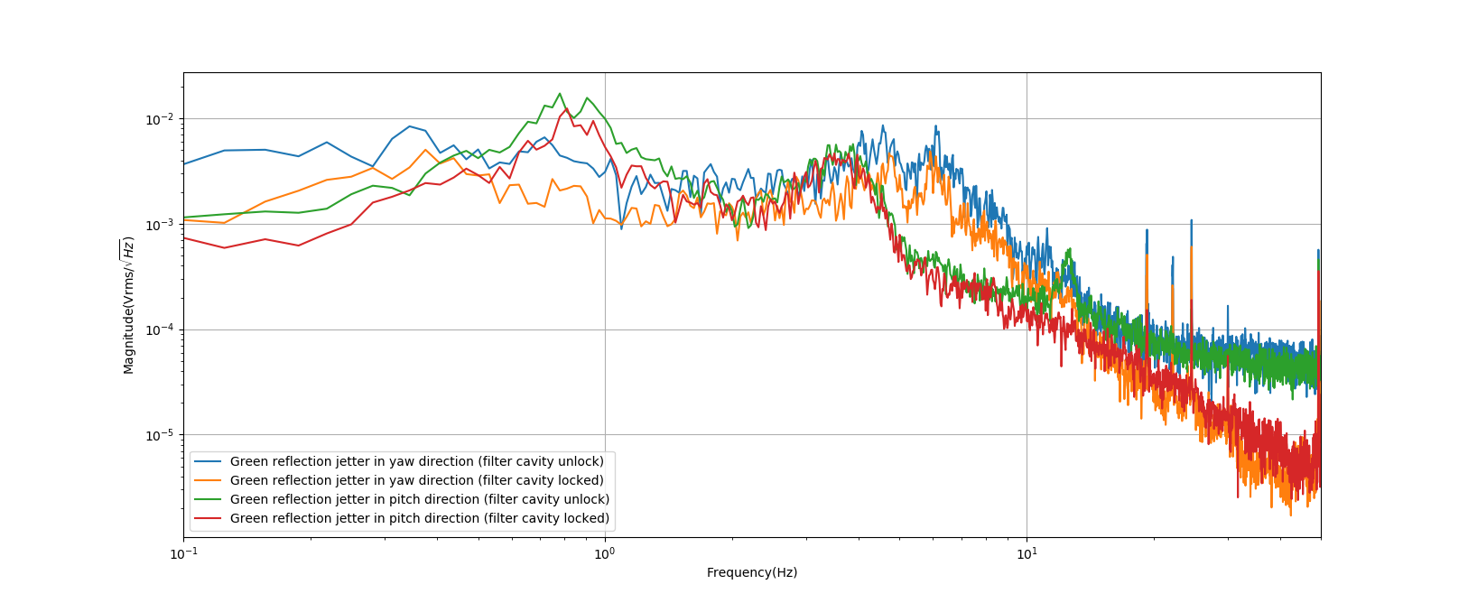
I did measurement first time just after the meeting, I measured the GR reflection beam jitter by QPD at yaw and pitch direction. I tried my best to center this beam and made the measurement. I also measured the beam jitter difference when the filter cavity is locked and unlocked. The result is attached in figure 1.
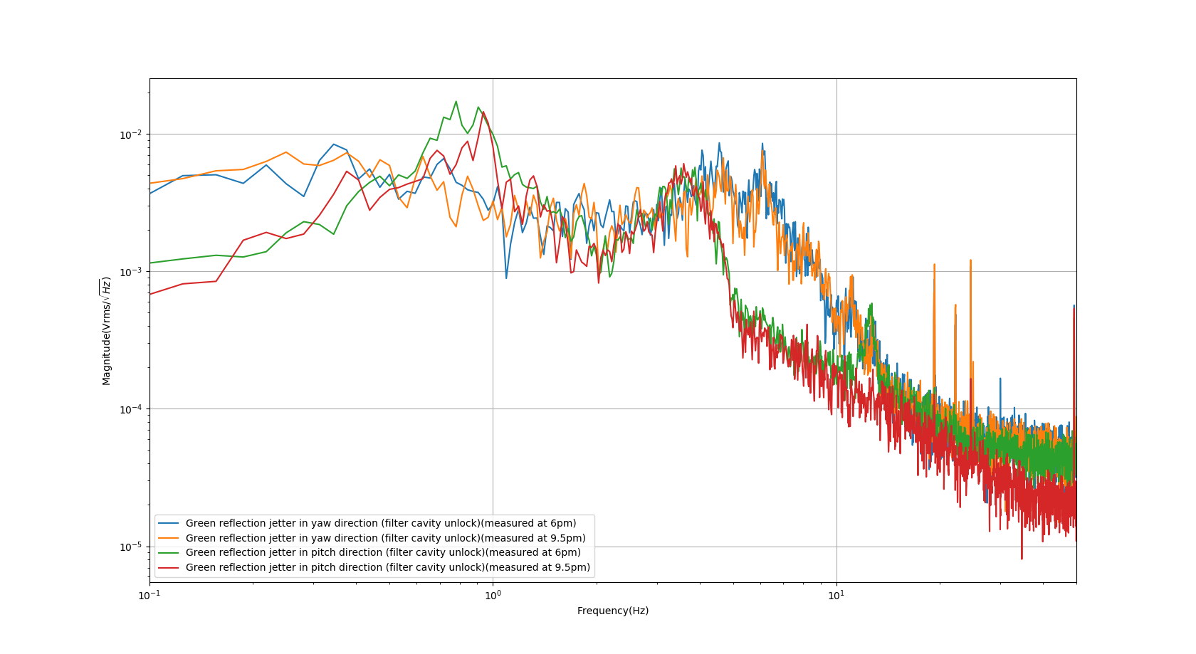
I did measurement again before leaving. This time I just measured when the filter cavity is unlocked. The comparison is in attached figure 2.
conclusion:
1. The lock of the filter cavity can reduce this beam jettering above ~10Hz. We know the correction signal we are sending to Main laser PZT is limited by laser noise above 10Hz. So I guess the lock of the filter cavity reduces the power coupling from higher-order modes to TEM00. And at low frequency, this is limited by the suspension. So if we engage the filter cavity length control, we may solve a bit this beam jittering problem. We should try to see this effect.
2. From the first plot, It seems pitch and yaw have different peaks. Yaw is worse at a higher frequency while the pitch is worse at a lower frequency.
3. From the second plot, it seems there is no obvious difference between 6 pm and 9.5 pm of beam jittering. I will check the situation in the morning and just after lunch.
Aritomi and Yuhang
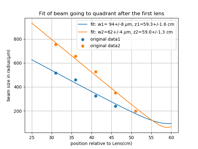
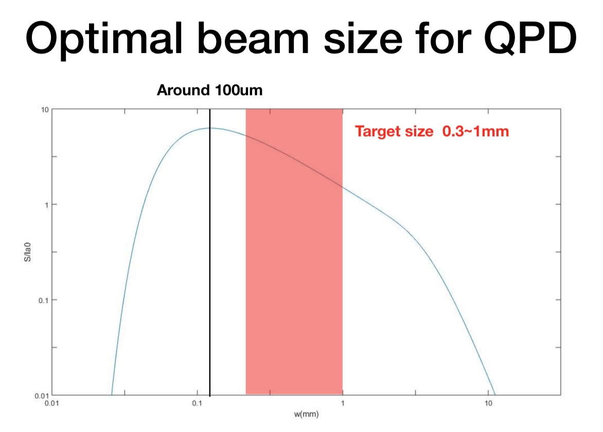
To make sure everything is going well, we decided to perform this measurement. From the simulation, beam waist should be 53.5cm after the lens and has size 146um.
From the measurement, the beam waist is 59cm after the lens and has a size around 80um. This is out of our exception.
Shall we adjust the telescope according to this measurement?
This is the light around the wall.
Here is difference when fluorescent light in TAMA is ON and OFF. Please turn it off when you want to measure small signal.
This is the light around the wall.
[Aritomi, Yuhang]
We could see BAB transmission (injection is 150uW) by CCD camera without amplification when IR is aligned and AOM frequency is optimized (Pic.1). We could also see BAB transmission with 11.5uW injection (Pic.2), so we can see CC transmission with current CCD camera.
[Aritomi, Yuhang]
| Mode | AOM frequency (MHz) | IR transmission |
| TEM00 | 109.03714 | 220 |
| HG30 | 109.22741 | 105 |
| HG10 | 109.42253 | 142 |
| HG40 | 109.62523 | 104 |
| HG20 | 109.8303 | 116 |
| offset | 92 |
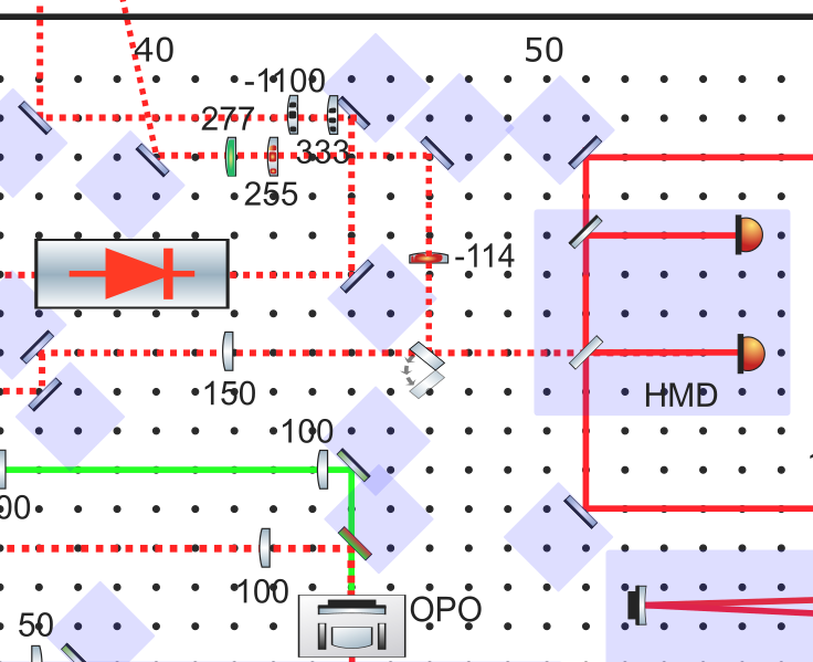
Here I put the position of lenses on bench for SQZ telescope. (comment to entry 1546)
For injection telescope, since we have no space to move now. So the solution is to buy RC4 from thorlabs. This new dovetail rail carrier will allow a movement of up to 3mm for 333lens and 10mm for -1100lens. And from the simulation, this is already enough range to improve mode matching. (this telescope is shown in black color in the attached figure 1)
Note: it seems lens333 is touching mirror, but it is not due to the small mirror mount we are using.
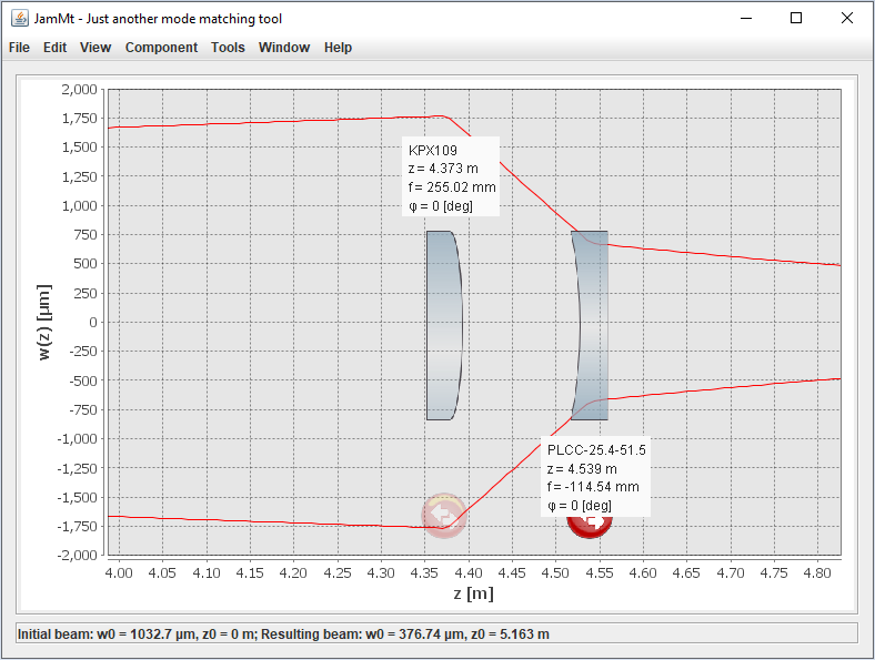
For reflection telescope, since we have only one superpolished lens. If we want to go on soon. We can temporily use KPX109 instead of CVI lens. From the simulation, these two telescope will be almost the same and PLCC51.5 will be at the same position. So it will also be easy to replace with superpolished lens in the future. (the red color lens is for the current implementation, lens in green color is the superpolished and will be implemented in the future)
The simulation of reflection telescope with newport lens is also attached as figure 2.
[Aritomi, Yuhang]
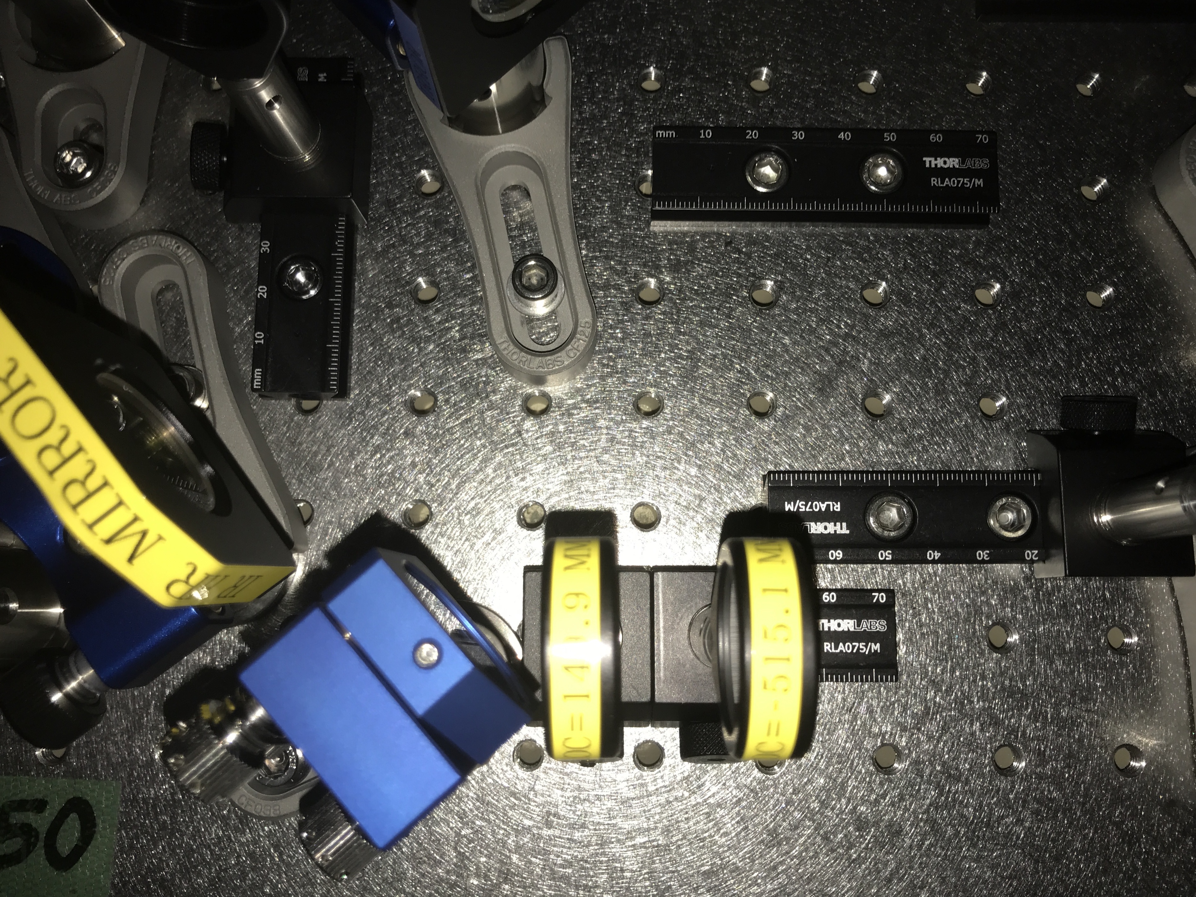
According to Yuhang's simulation (latest simulation is a bit different from this), we installed superpolished lens (PLCX-25.4-149.9-UV, PLCC-25.4-515.1-UV) for injection telescope. Unfortunately the two lenses are very close with each other (Pic. 1) and cannot be moved. We'll continue this setup for the moment and if mode matching is problem, we'll think another configuration.
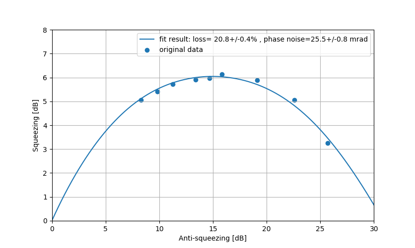
To extract loss and phase noise information and estimate error, the fit version of entry 1571 is attached here.
Aritomi and Yuhang
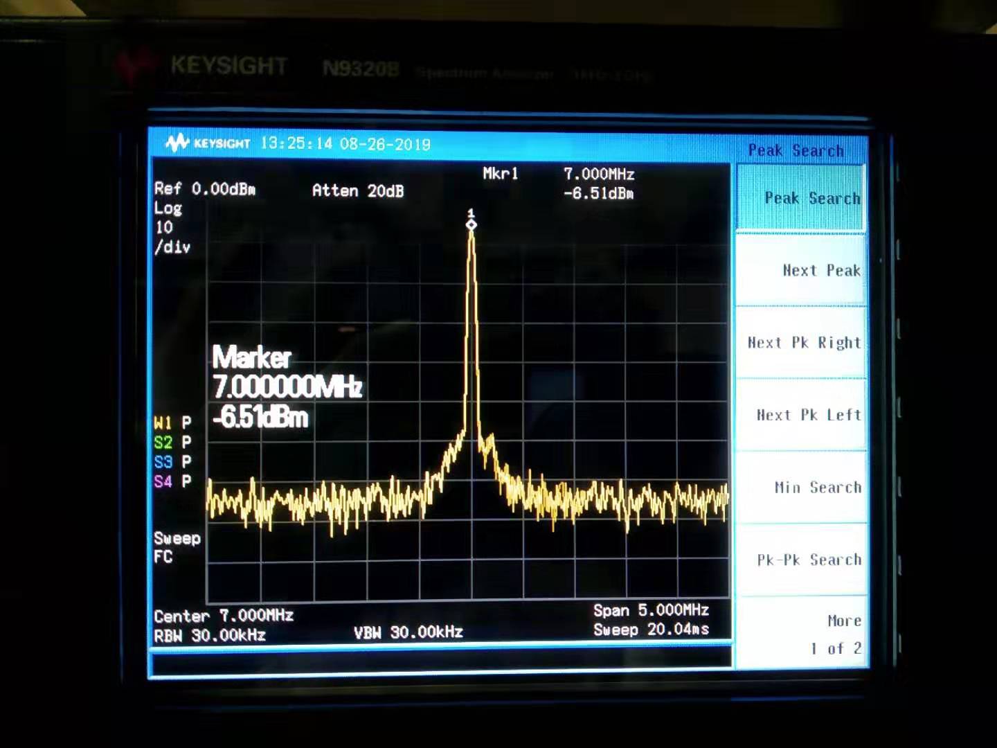
The output of DDS board is -6.5dBm(shown in the attached figure 1). While the AA demodulation board requires 4-15dBm signal. And this signal should come from the same DDS board with the modulation we send to the EOM (this is board 2).
So our strategy is:
1. amplify this signal by using RF amplifier ZHL-2 (it should have a gain of 16dB from specification)
2. use a RF splitter Z99SC-62-S+ (0-500MHz) to seperate this signal (the signal will degrade by 3dBm by splitting and loss 0.5dB because of losses)
3. in the end, from calculation, we should have identical signal 6dBm. And this is meeting our requirement.
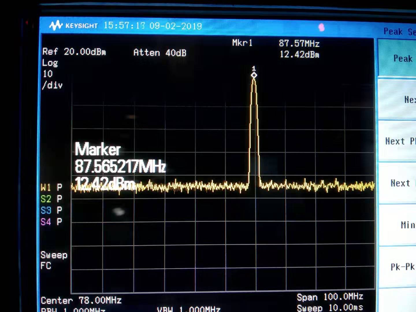
Then we measured the signal. The signal after RF amplifier is 12.4dBm(shown in attached figure 2), this means the gain is 19dB.
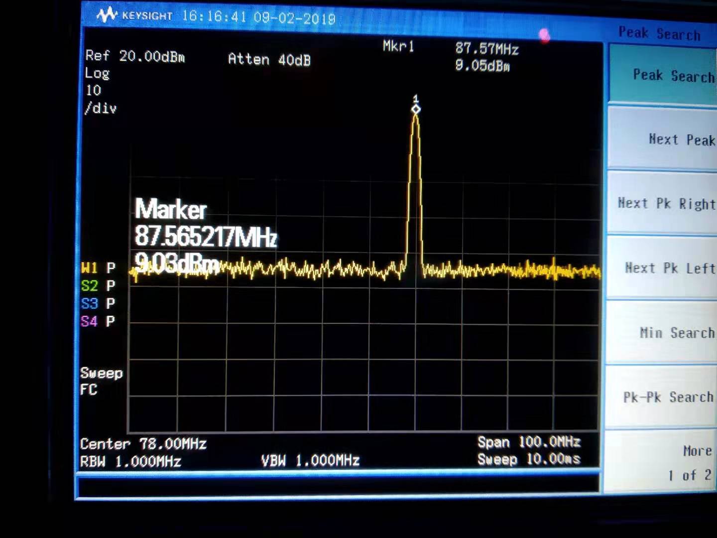
The signal after RF splitter is 9dBm(shwon in the attached figure 3).
So we can keep this configuratiuon for AA system.
Simon
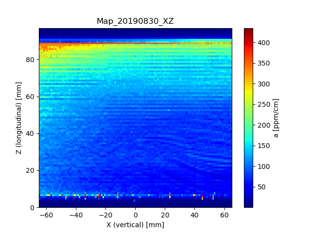
Attached to this report is the result of mapping the absoprtion of spare ETMY in XZ directions. The map is oriented with the side facing the IU on top and the side facing the optical table on the left, so don't get confused!
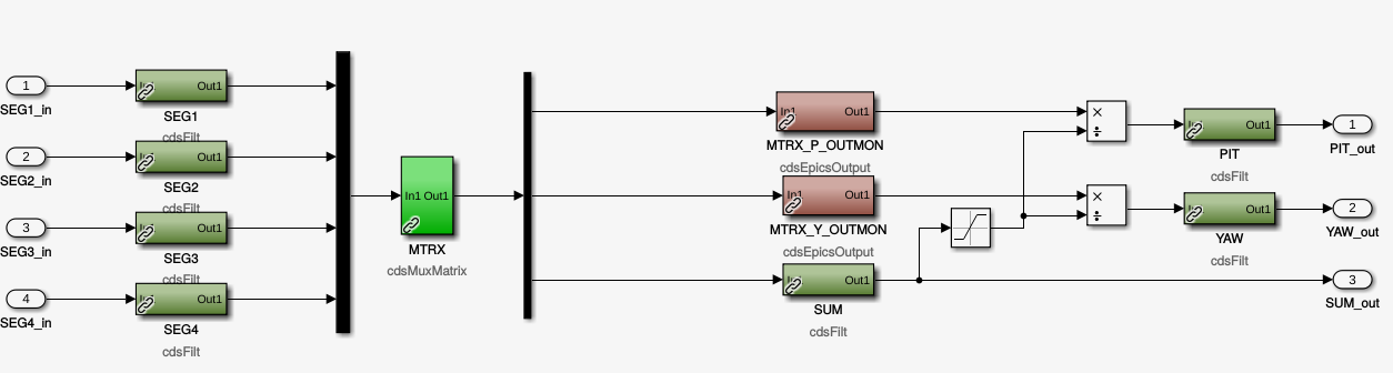
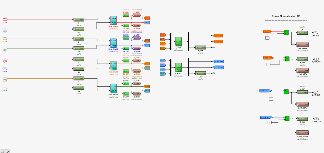
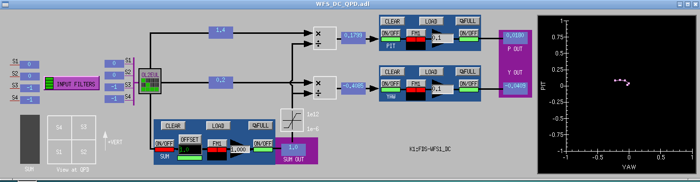
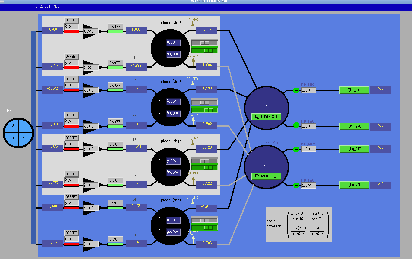
I implemented the real time and MEDM models for reading signals from WFS and convert it into pitch and yaw (including options for filtering, normalization, etc..).
The code is basically copied from KAGRA one. I implemented two subsystem models: one for DC signals (pic1) and one for RF (pic2). The corresponding medm screen are shown in pic3 and pic4.
I used two common medm screens model and passed it different variables, corresponding to the two WFS we plan to used (WFS1, WFS2). Everything seems to work fine.
At some point I mistakenly took a snapshot of the epic channels values just after restarting the model, so that the default snapshot file was overwritten with the initialized values. I contacted Miyakawa-san that explained me that every time the model is restarted a snapshot is automatically stored in the folder /opt/rtcds/k1/kagra/target/k1fds/k1fdsepics/burt wih. So I could restore the previous epic channel values by using this last snapshot file.
The next step will be to implement the sensing matrix and the feedback loop to the mirrors.
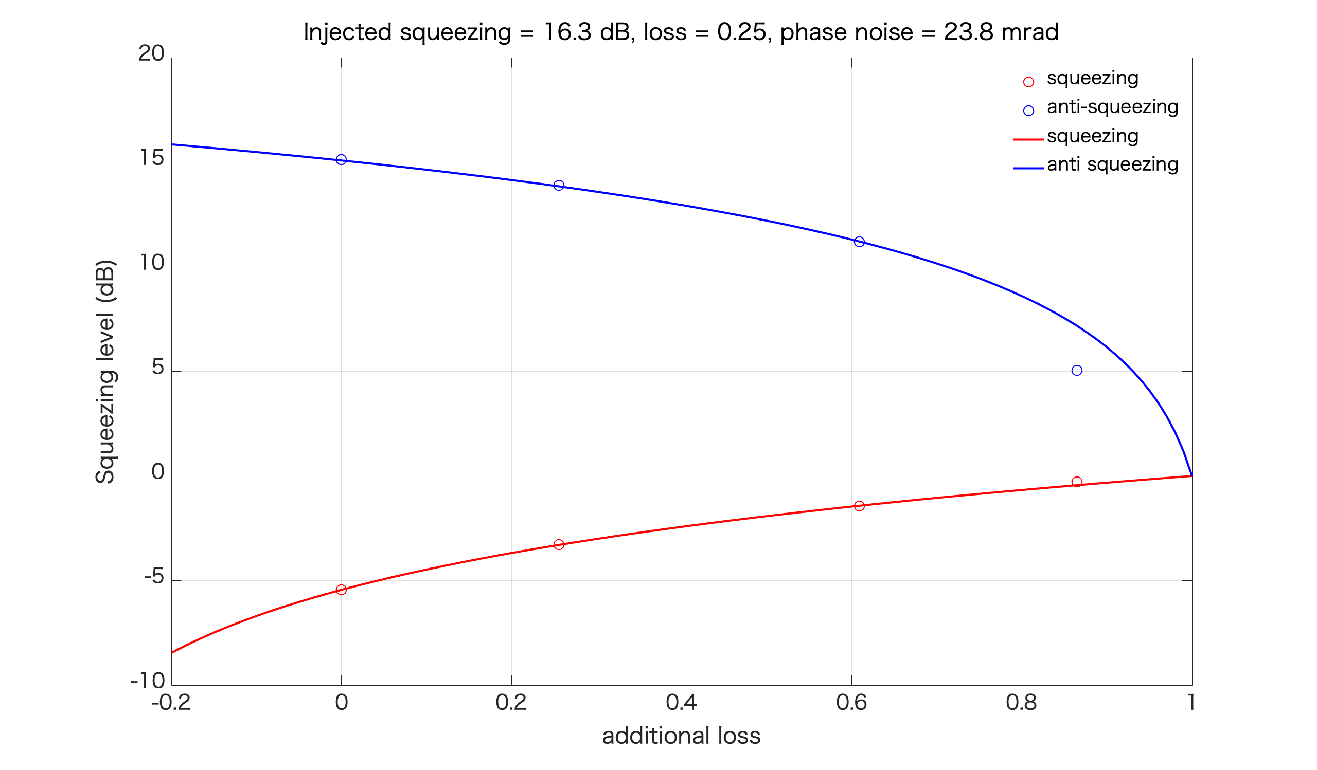
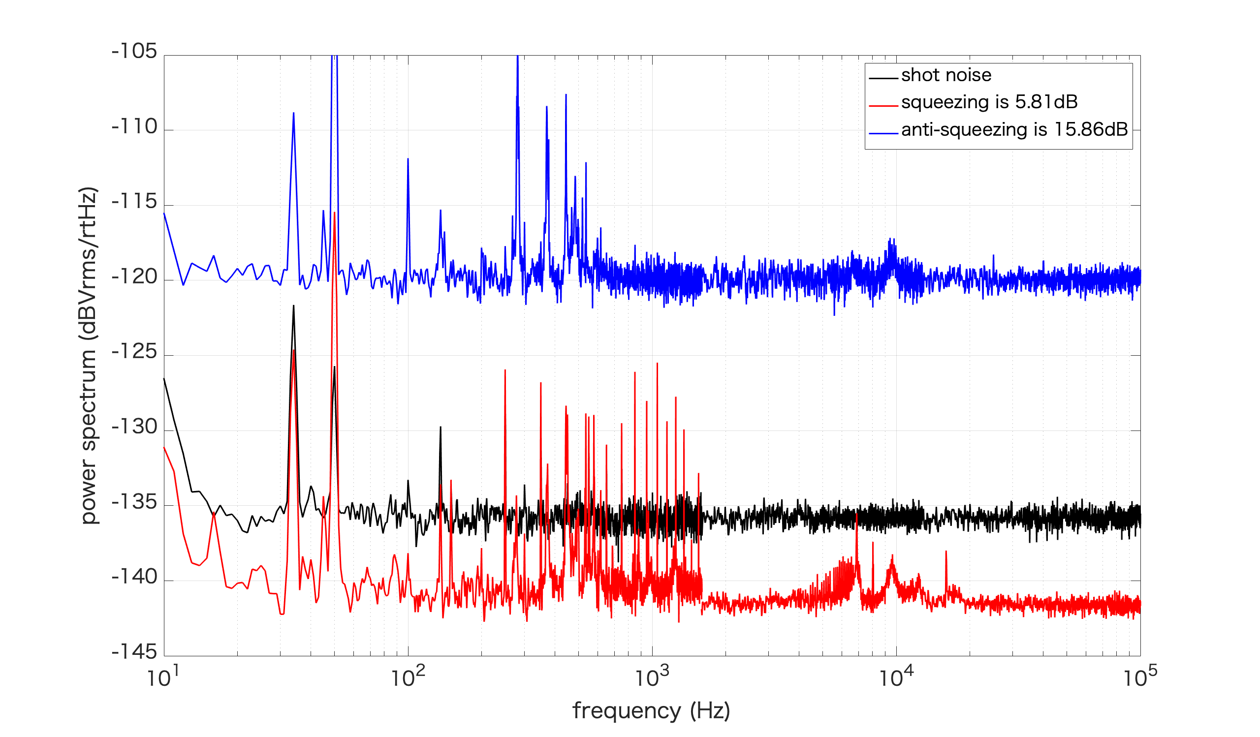
To confirm the result of loss and phase noise, I measured squeezing and anti squeezing with different loss. The way to inject additional loss is to put HWP in squeezing path and rotate the polarization. The loss can be estimated by measuring the visibility. I assumed mode matching is 99% during this measurement.
| HWP angle (deg) | Vmax (V) | Vmin (V) | V_BAB (V) | Additional loss | squeezing (dB) | anti squeezing (dB) |
| 0 | 3.2 | 1.04 | 0.156 | 0 | 5.45 | 15.13 |
| 10 | 3.06 | 1.18 | 0.116 | 0.256 | 3.29 | 13.9 |
| 20 | 2.8 | 1.44 | 0.061 | 0.609 | 1.43 | 11.19 |
| 30 | 2.48 | 1.78 | 0.021 | 0.862 | 0.29 | 5.04 |
I fitted squeezing level with 3 variables which are injected squeezing and loss and phase noise. The result is injected squeezing = 16.3dB, loss = 25%, phase noise = 23.8 mrad. This is consistent with previous loss and phase noise measurement.
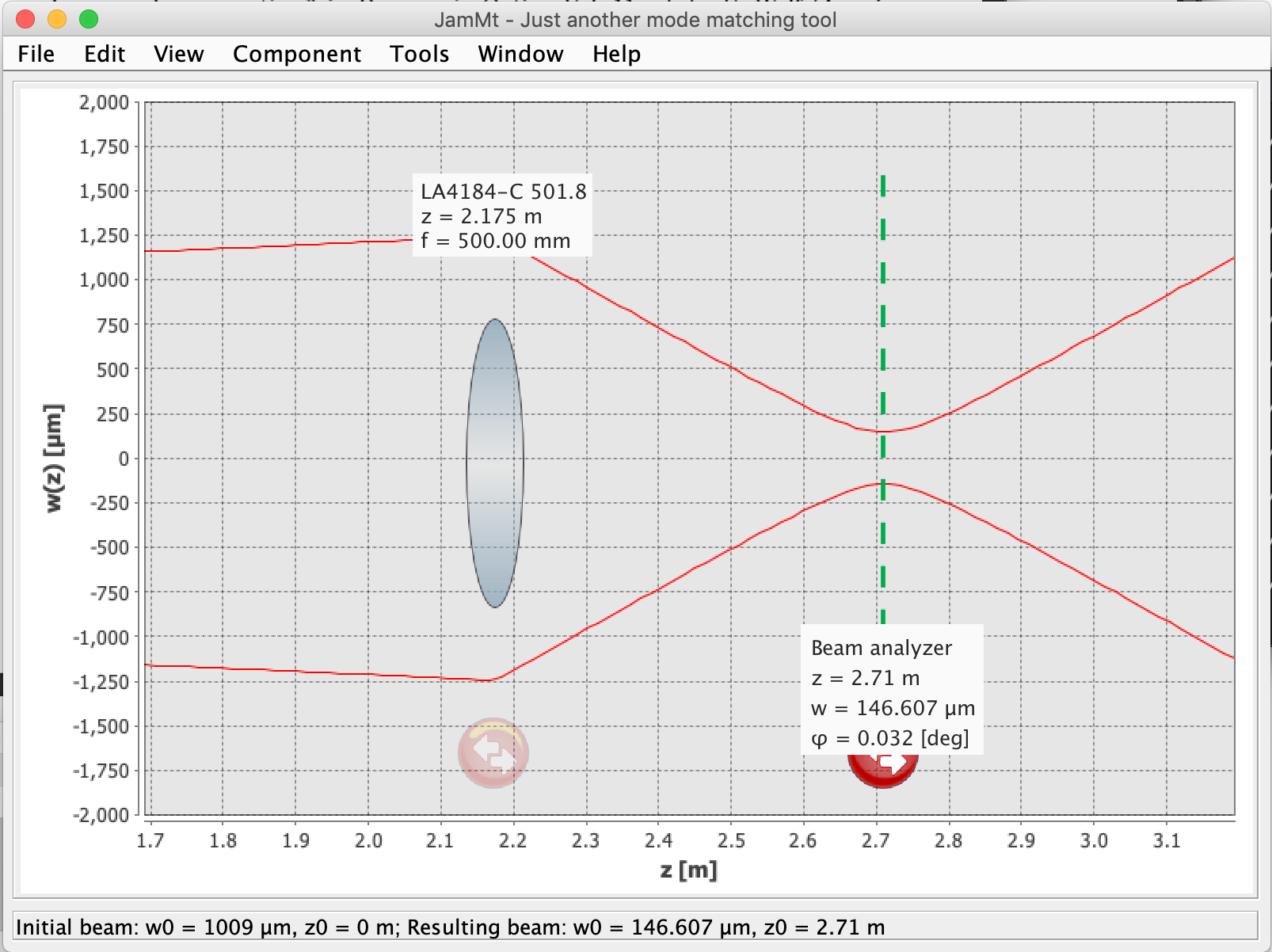
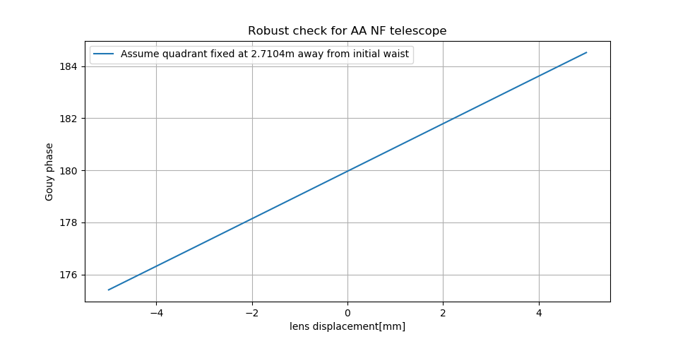
According to the beam parameter of entry 1046 and the telescope design from yuefan(entry 1564), I simulated the beam situation again. But it seems not the same with yuefan simulation. But anyway I checked the robust for the NF telescope. The FF telescope is quite different from yuefan design, I will confirm with yuefan what makes this difference. And do the robustness check soon.
Difference one: the distance from L1 to NF quadrant is 0.535 (in my case) and 0.65 (in yuefan case)
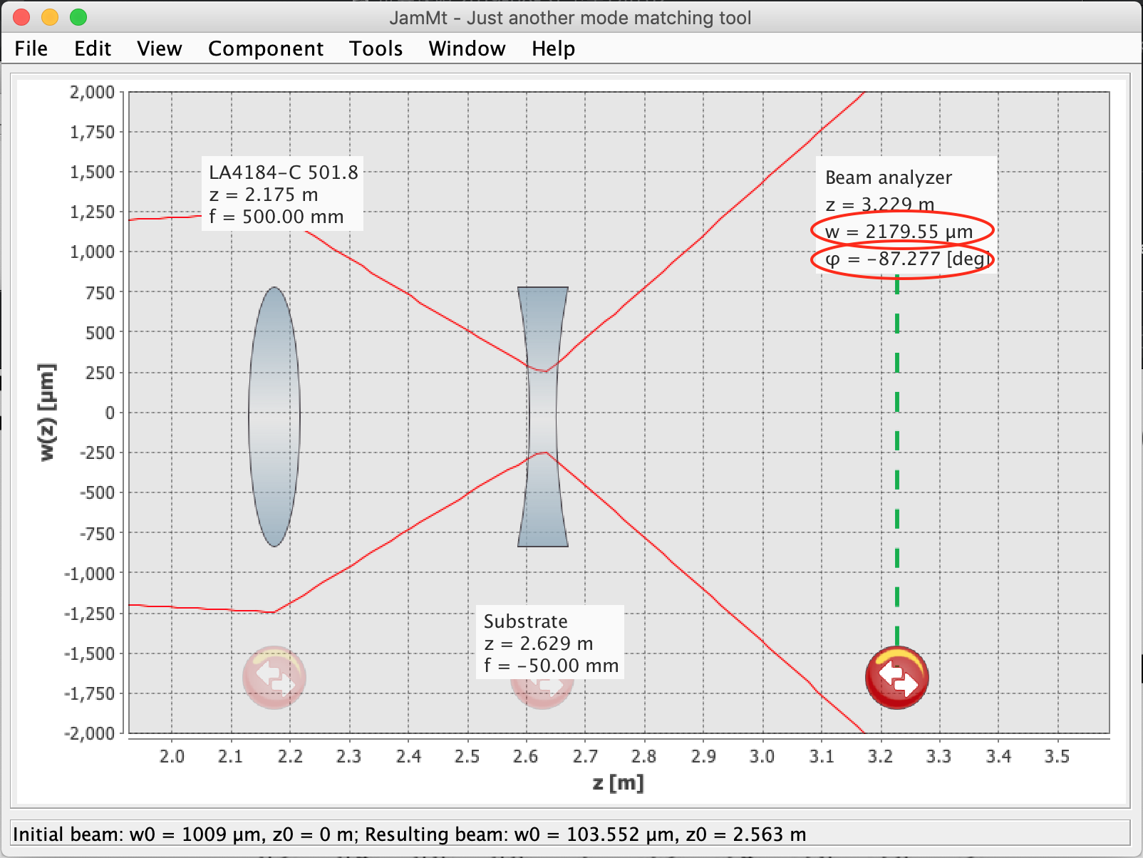
Difference two: I used the same distance with yuefan design, but the gouy phase is 87.277(in my case) and 90.2(in yuefan case)
Notice: from the simulation, the beam size for FF quadrant (if I use yuefan design) is 2.179mm (radius). This is 2 times larger than the requirement. We should also check this.
I confirmed with yuefan that we are using the same initial beam parameter. Also, yuefan told me we have a tolerance of several degrees for the gouy phase. So I think with our hand we can have a precision within 1 cm, and in this case, it should be fine if we don't use the first lens on the rail. However, if we consider the distance estimation error from lens1 to NF quadrant PD, we may have another 1cm of error. In this case, maybe we should use rail.
Or we can just measure the beam parameter with beam profiler after BS and find out where is the beam waist. Then put quadrant PD in the position of the waist.
Or we can tell if we are seeing the decoupled motion of cavity by looking at the output signal of quadrant PD. Then we can decide the position of quadrant PD.
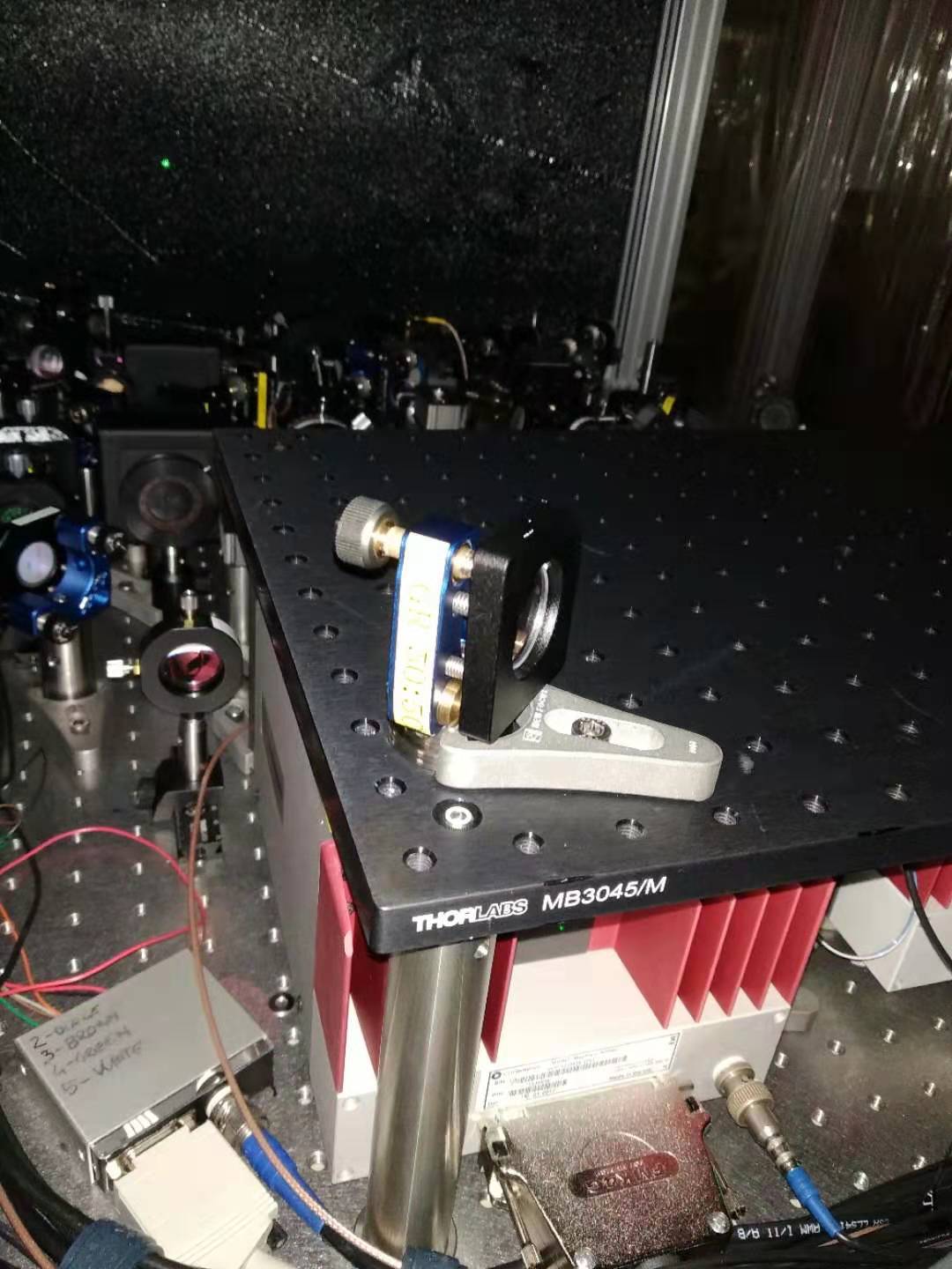
The components until the second layer were installed, and also 50:50 BS was installed. (attached picture 1 and 2) I also adjusted the lens and mirror position and angle, so that the beam is going as straight as possible.
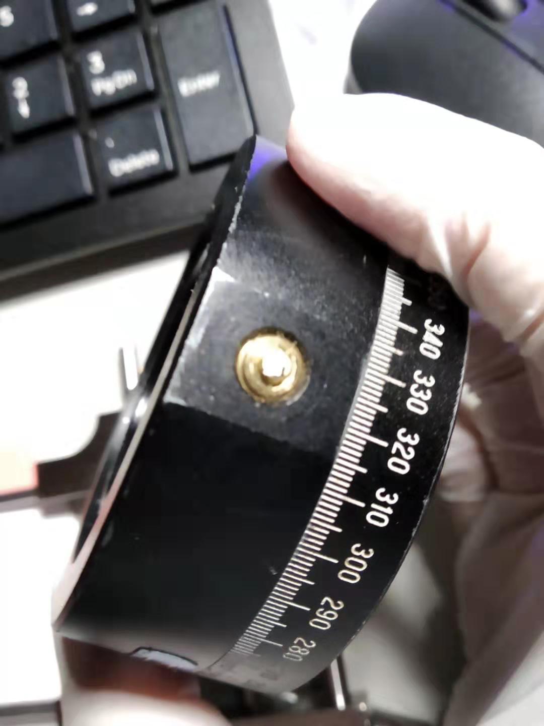
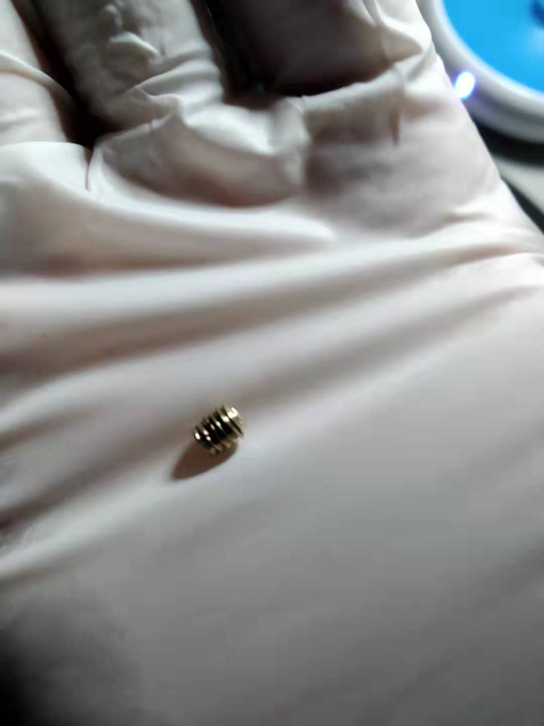
Actually, I would like to measure the beam after BS to confirm everything is fine, but I broke the screw of beam profiler. I tried to replace the broken screw but seems not possible. (attached picture 3 and 4 are broken screw)
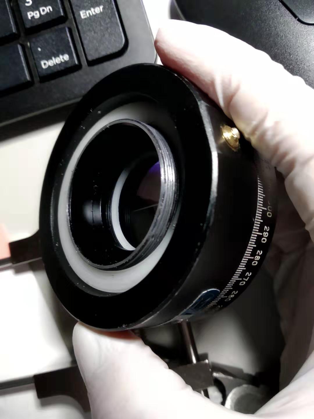
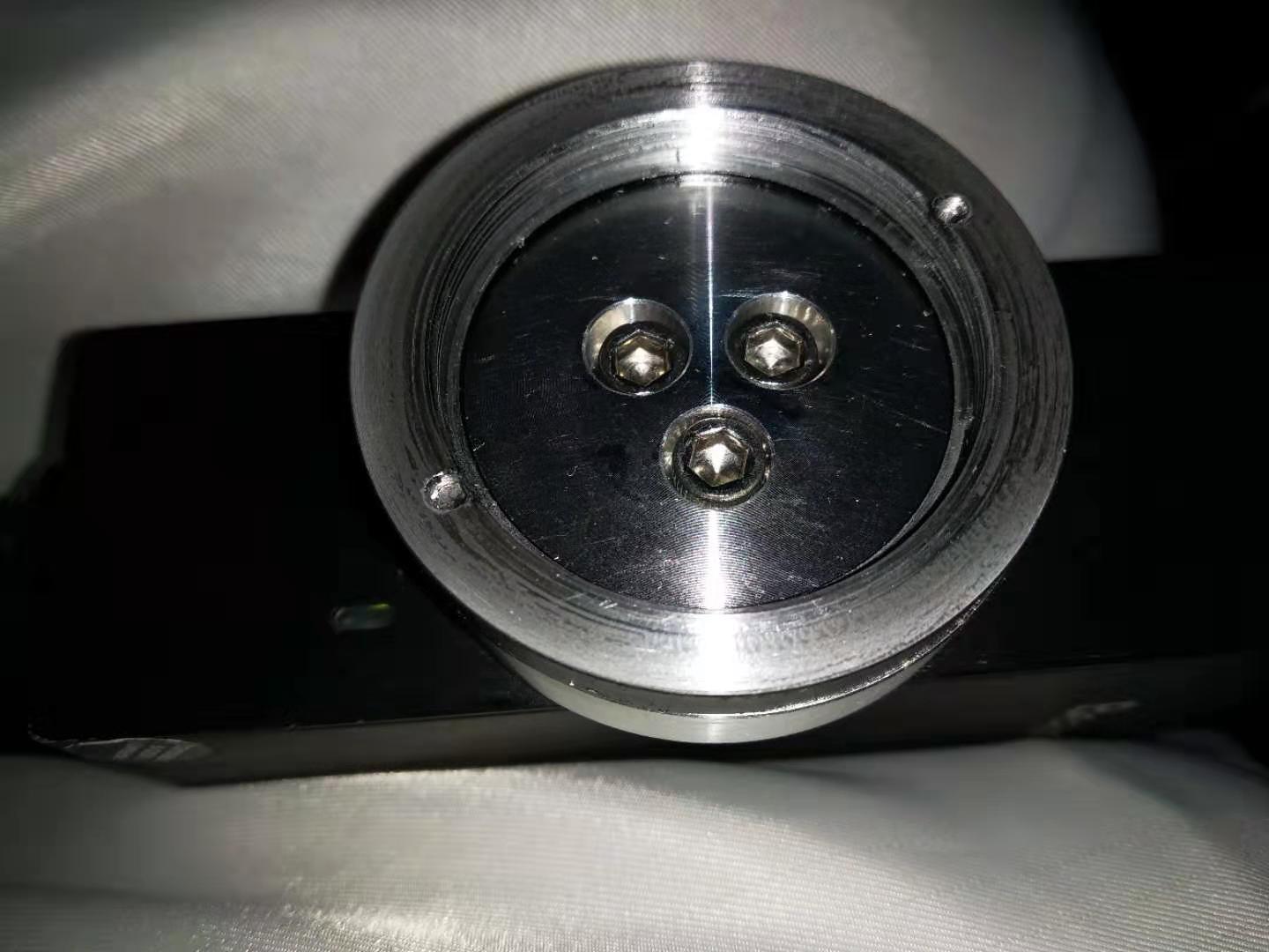
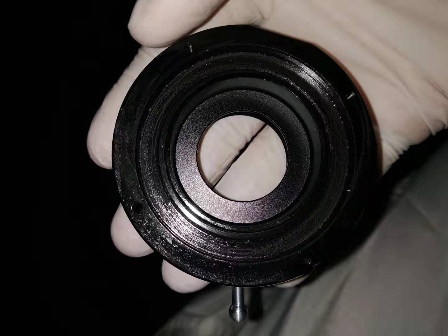
We could also just replace the mount. Up to now, I couldn't find a suitable mount. (See attached picture 5, 6 and 7)
Figure 5: sigma waveplate mount(originally we were using this)
Figure 6: connection part of the beam profiler
Figure 7: the wave plate mount(we usually use on bench, we have a lot but seems not suitable)
Simon
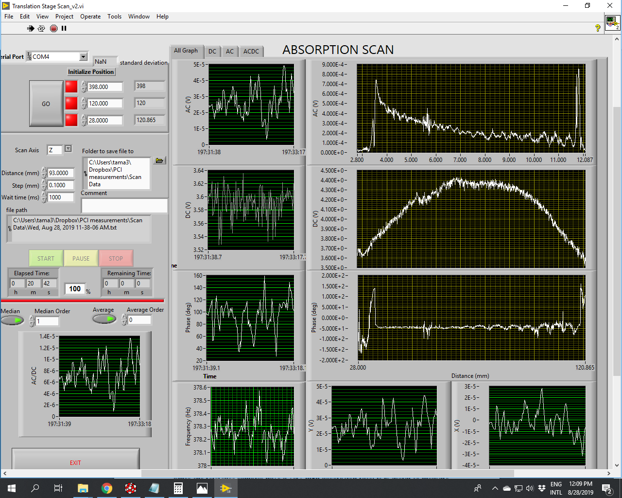
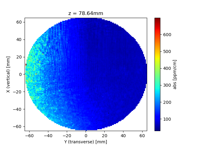
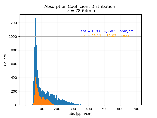
With the recent recalibration of the PCI, I took another XY-map at the center in longitudinal direction. The results are attached as png pictures.
Compared with the results of the measurements before, we can see that the mean value of the absorption coefficient is much lower now (all given in ppm/cm):
| Center + 33mm | Center | Center - 33mm | |
| Measurement on Aug. 15-20 | 159 ± 77 | 195 ± 102 | 342 ± 189 |
| Measurement on Aug. 29 | (107) | 120 ± 69 | (231) |
| Measurements from Caltech | 83 ± 31 | 99 ± 50 | 216 ± 108 |
The numbers in parentheses are those for the older measurements but with the recalibrated bulk-reference value. Note that for the "Center" value of the most recent measurement the absorption coefficient would increase to 177 if using the old reference value.
It would be of course better to see the measured mean-values also for the other Z-positions but I don't know whether there is time.
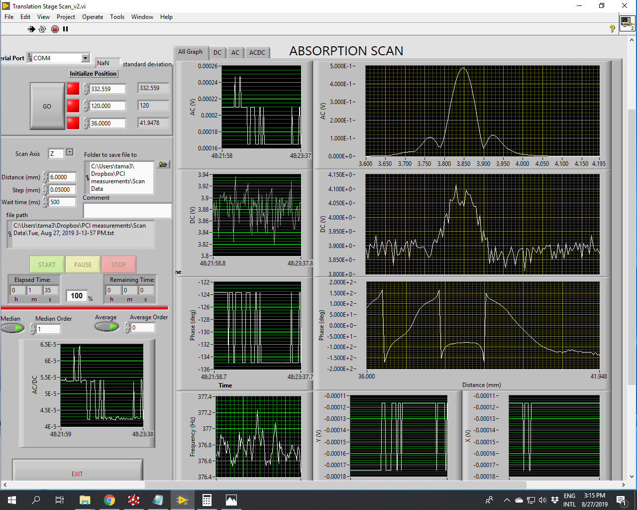
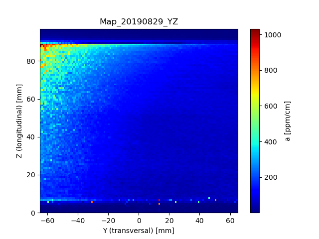
Attached is also a map in YZ-direction, taken at X = 398 (also the center). It clearly shows an increase in absorption toward the outgoing surface (smaller Z) and oriented on the left-hand side (the map shows the situation as seen from above the test-mass with the incoming surface on the bottom).
The mean value within the relevant region (the substrate without the surface) is 148 ± 115 ppm/cm.
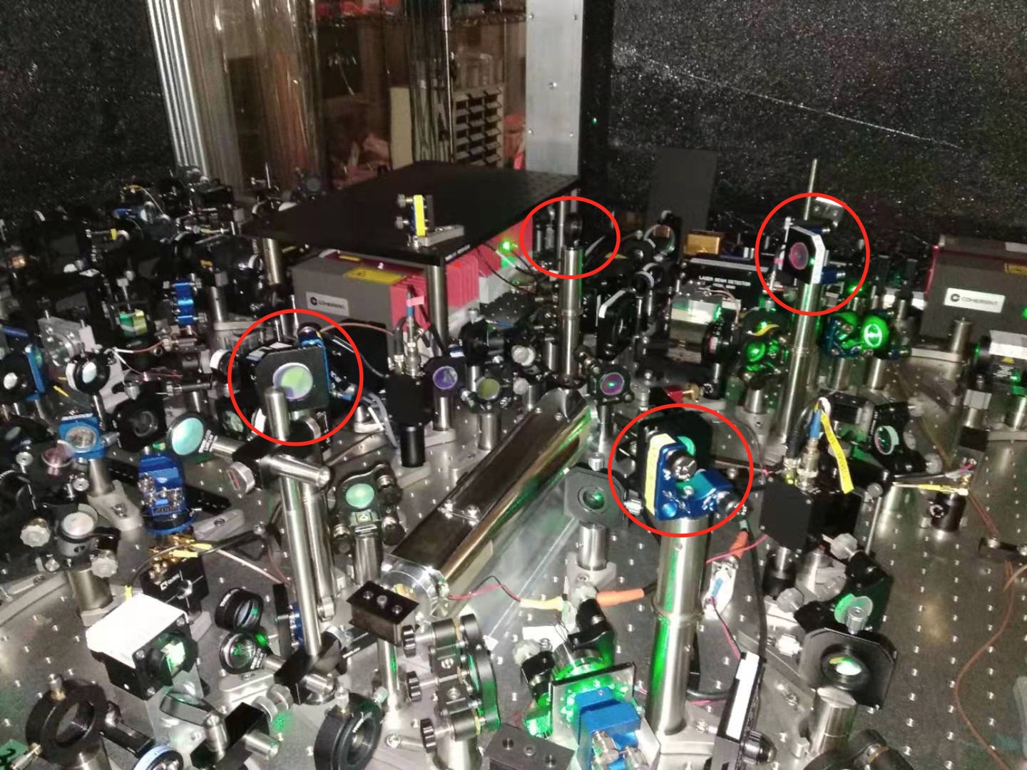
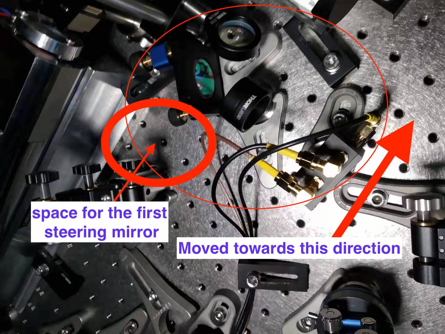
1. I found there was no space for the AA first steering mirror, so I moved the steering mirror, lens and PD for FC lock closer to FI. The situation is shown in the first attached figure.
2. The BS now we are using for splitting GR reflection is coated for IR since we don't have GR BS. We decided to order BST10, and hopefully it will arrive next week.
3. The periscope for rising up GR reflection is done for a beam height of 206.4mm. (attached figure 2)
4. The three steering mirror and one lens on the bench is prepared. (attached figure 3)
Simon
(This is the report of the last two days activities)
I finished the recalibration of the PCI were I slightly adjusted the position of the pump-beam and used (now) the correct way of the surface calibration sample.
R_surf = AC_surfref/(DC_surfref*P_in*abs_surfref) = 17.2 [1/W]
where AC_surfref = 0.48V, DC_surfref = 4.07V, P_in = 0.031W and abs_surfref = 0.22
R_bulk = AC_bulkref/(DC_bulkref*sqrt(T_bulkref)*P_in*abs_bulkref) = 0.784 [cm/W]
where AC_bulkref = 0.09V, DC_bulkref = 4.8V, T_bulkref = 0.55, P_in = 0.031W and abs_bulkref = 1.04/cm
Both values indicate that the AC/DC ratio is higher than before and hence, the crossing-point is indeed more at the pump beam's waist.
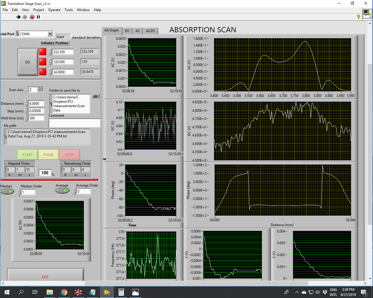
After the calibration, I changed back to the spare ETMY and made a scan along Z (c-axis) where you can see some interesting structures both in AC and phase at around Z=55 and Z>90 (see attached screenshot).