NAOJ GW Elog Logbook 3.2

[Yuhang, Aritomi]
We changed plate BS for homodyne to cubic BS and aligned homodyne with s pol. Visibility is 0.988 which means loss from visibility is 2.4%. However, squeeze level is same. It seems that squeeze level is limited by unknown loss. Now we suspect that loss of OPO (escape efficiency) is large.
Simon
As there are some doubts about the linearity of the input-polarization, I checked the HWP and can confirm that it is not an accidentally taken QWP (I changed the angle to confirm its periodicity of 45deg).
In order to further increase the linearity, I have put a QWP in front of the HWP and looked for the S-pol minimum (while maximizing P-pol) on the sensors when the mass was out of the beam-path. I could reach a minimum of ~1.2 mV with having ~384 mV on P-pol-sensor. Turning the HWP by 45 degrees, I reached a S-pol maximum of ~312 mV and a P-pol minimum of ~0.9 mV.
Those are much better numbers than we had before so that we can say to have a good linearization now!
With those changes on the setup and setting the initial polarization to S, I started mapping ETMY.
Matteo, Eleonora, Simon
(Report from July 30th 2019)
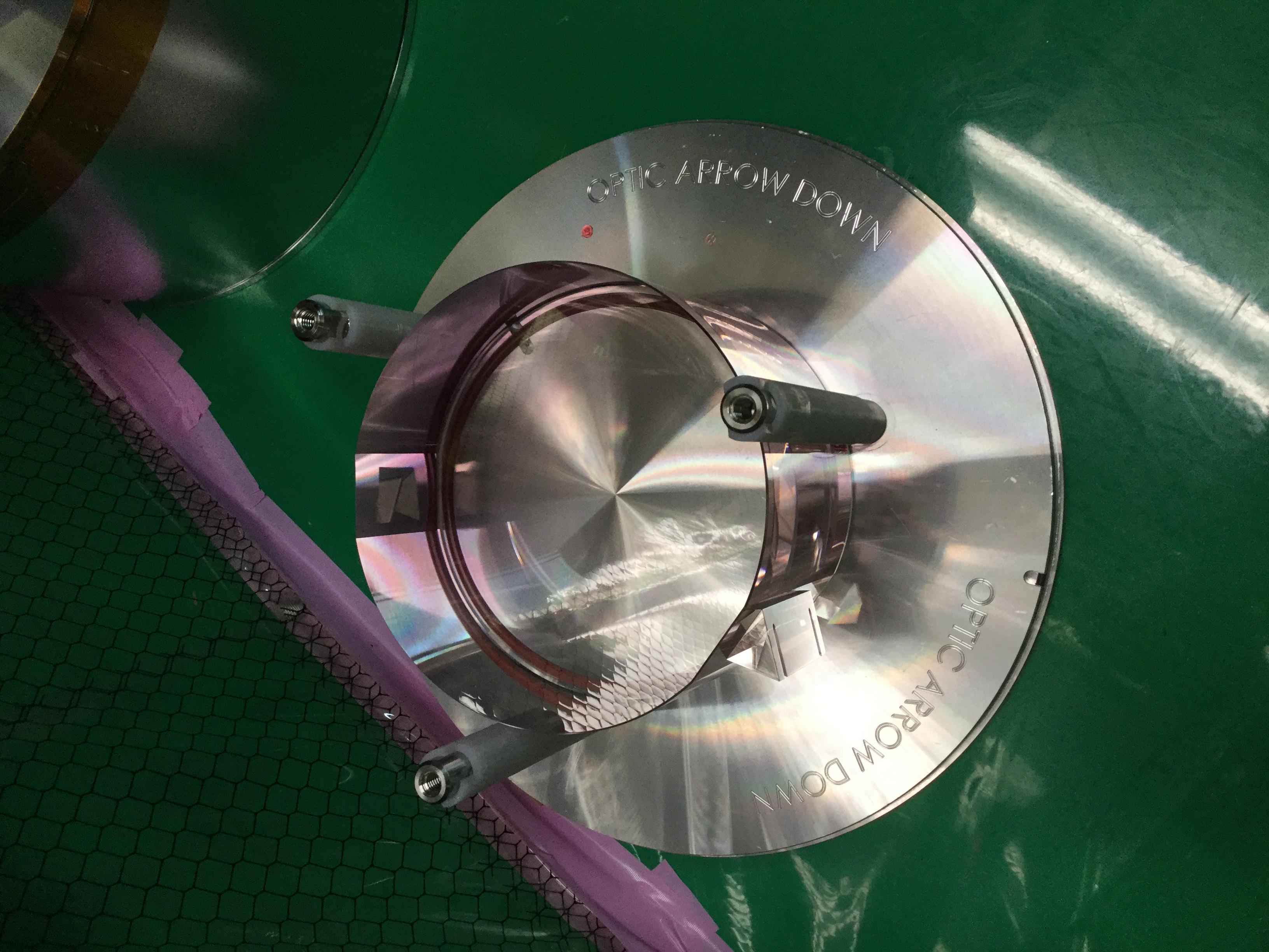
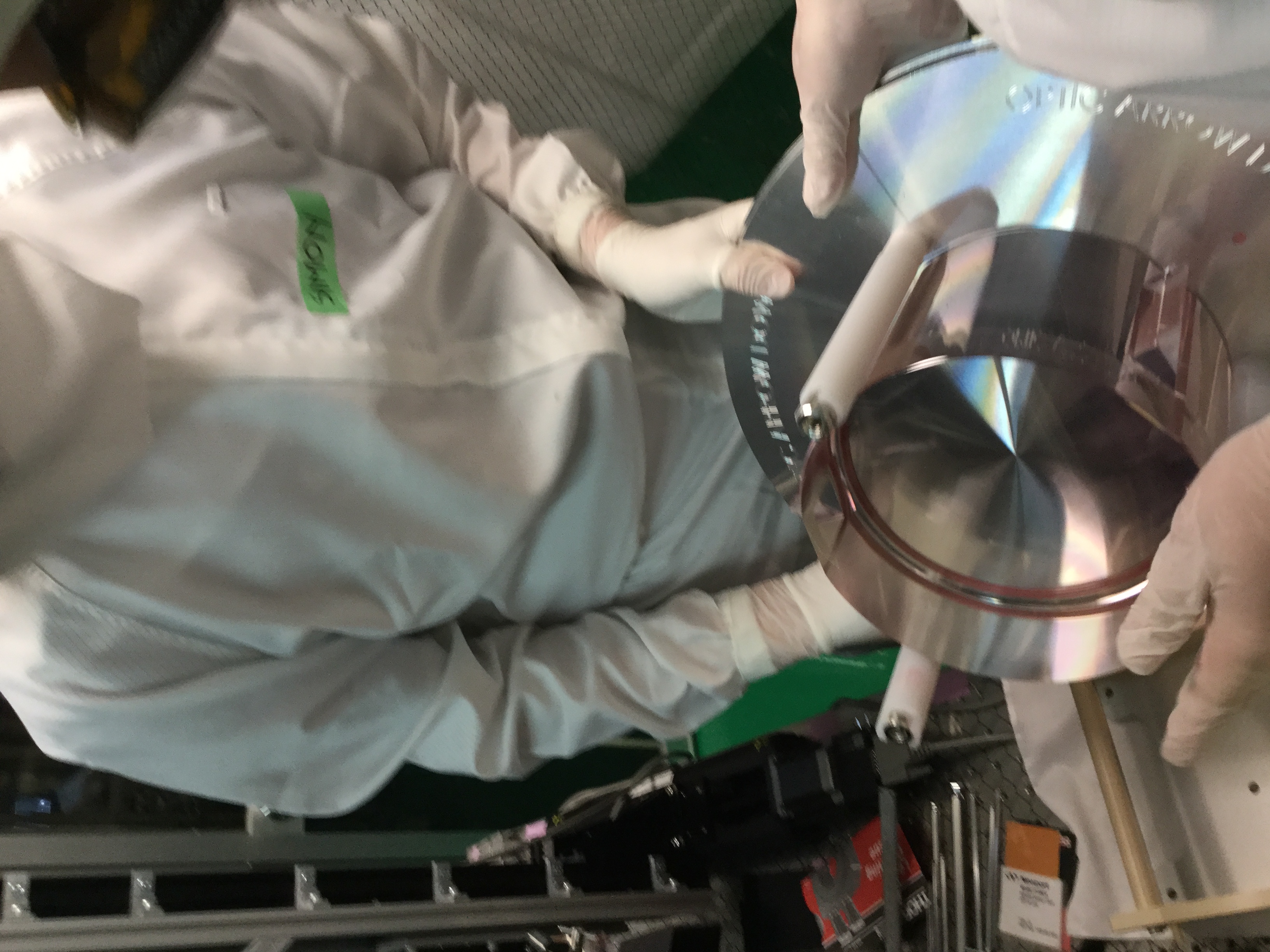
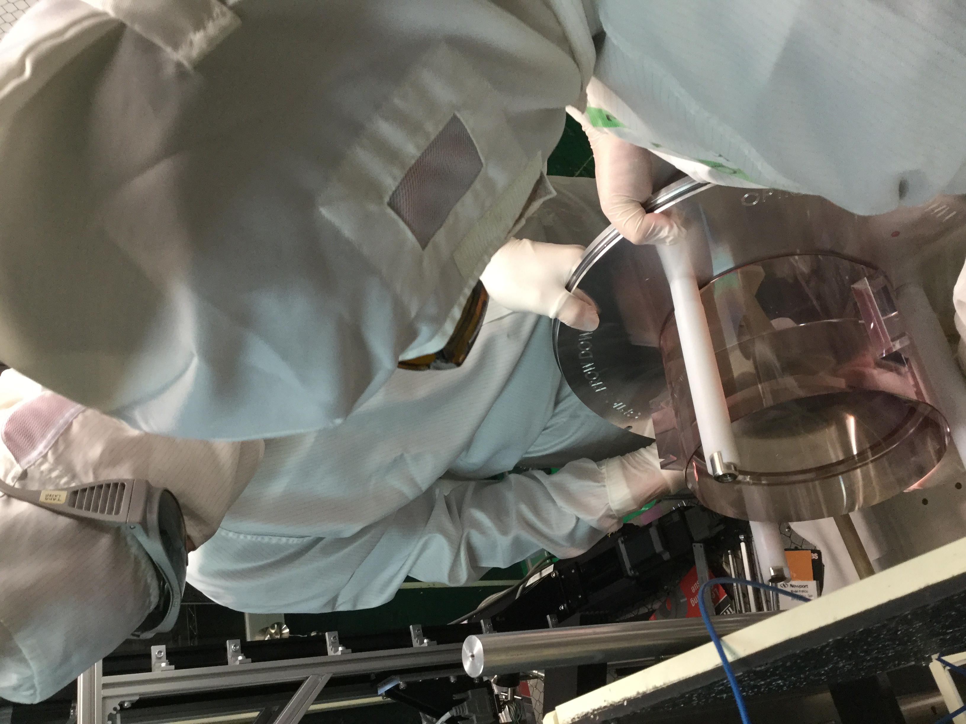
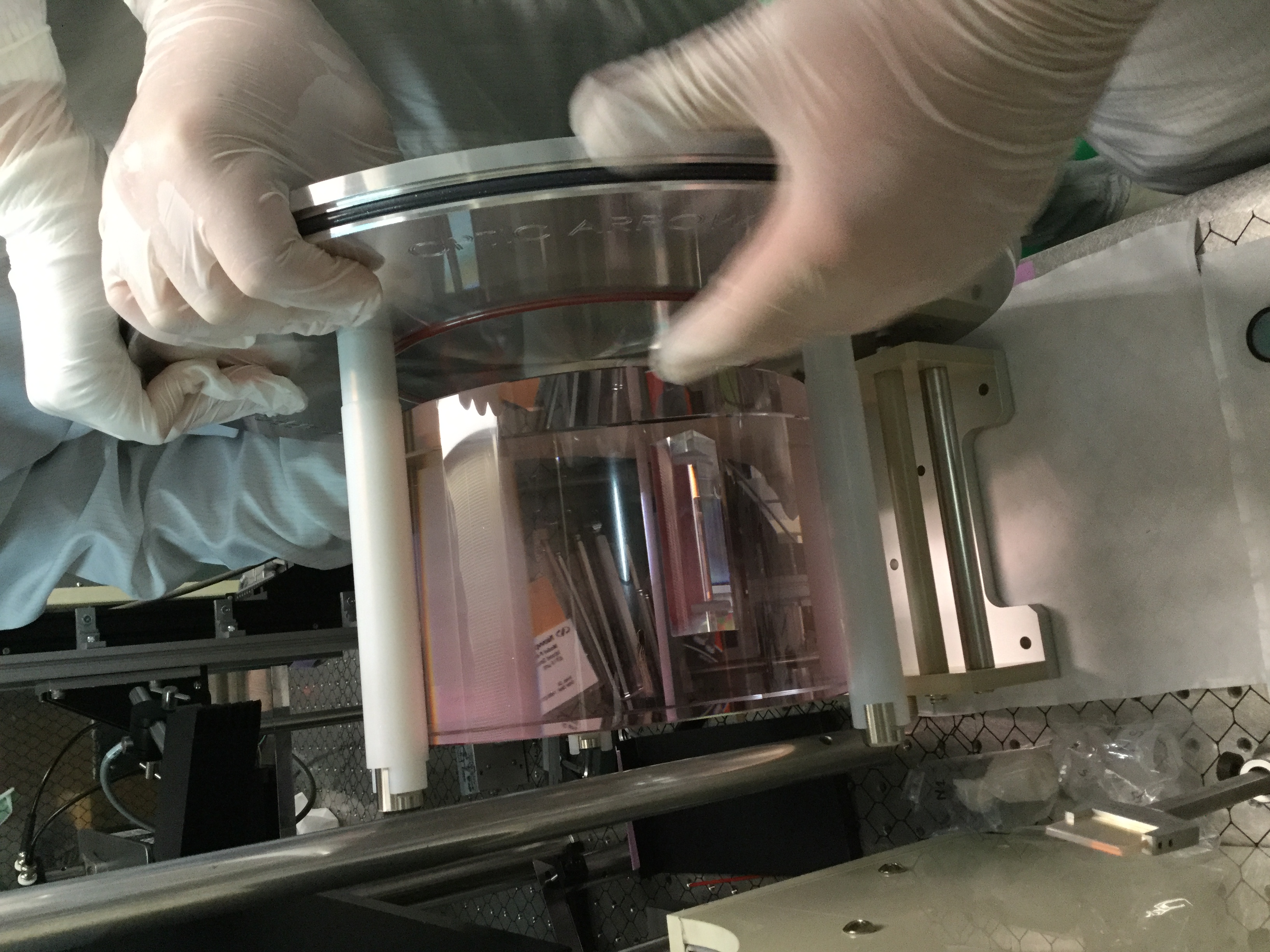
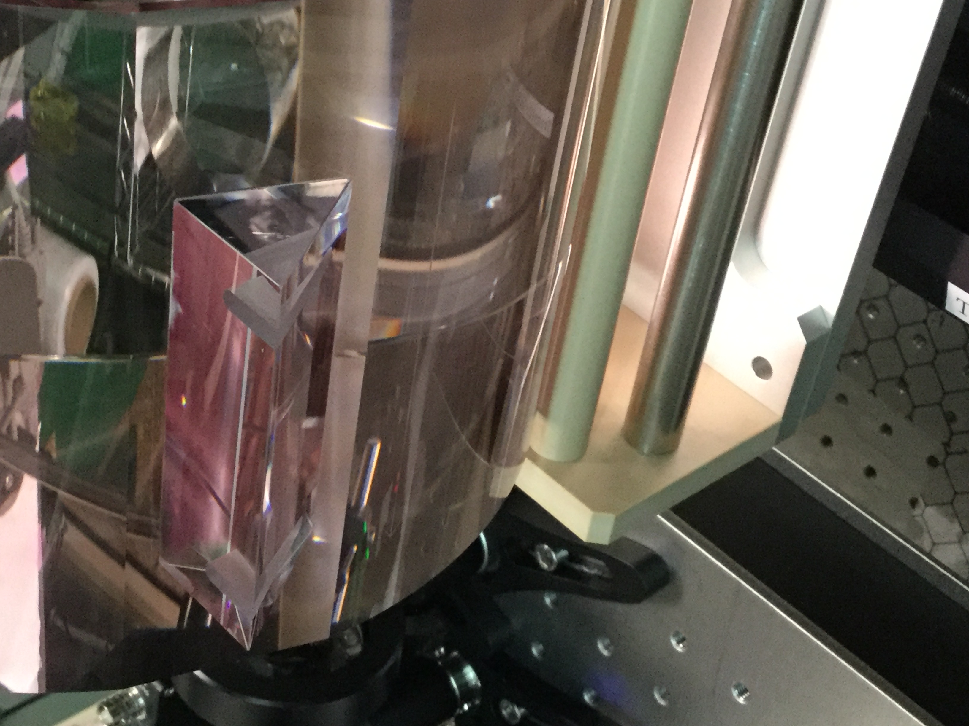
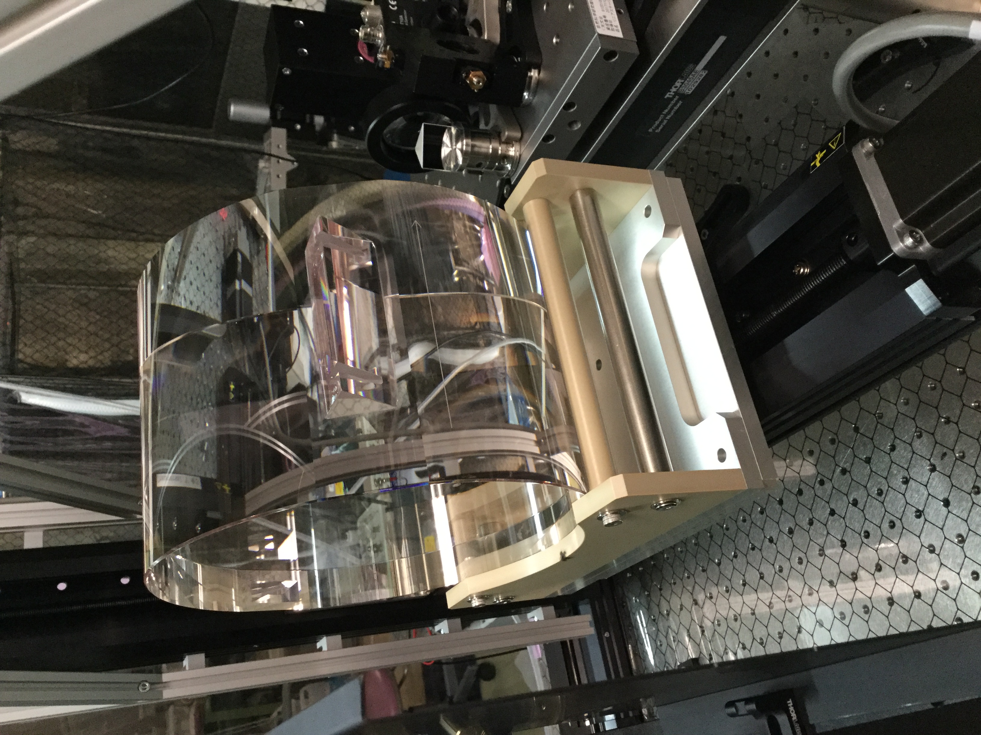
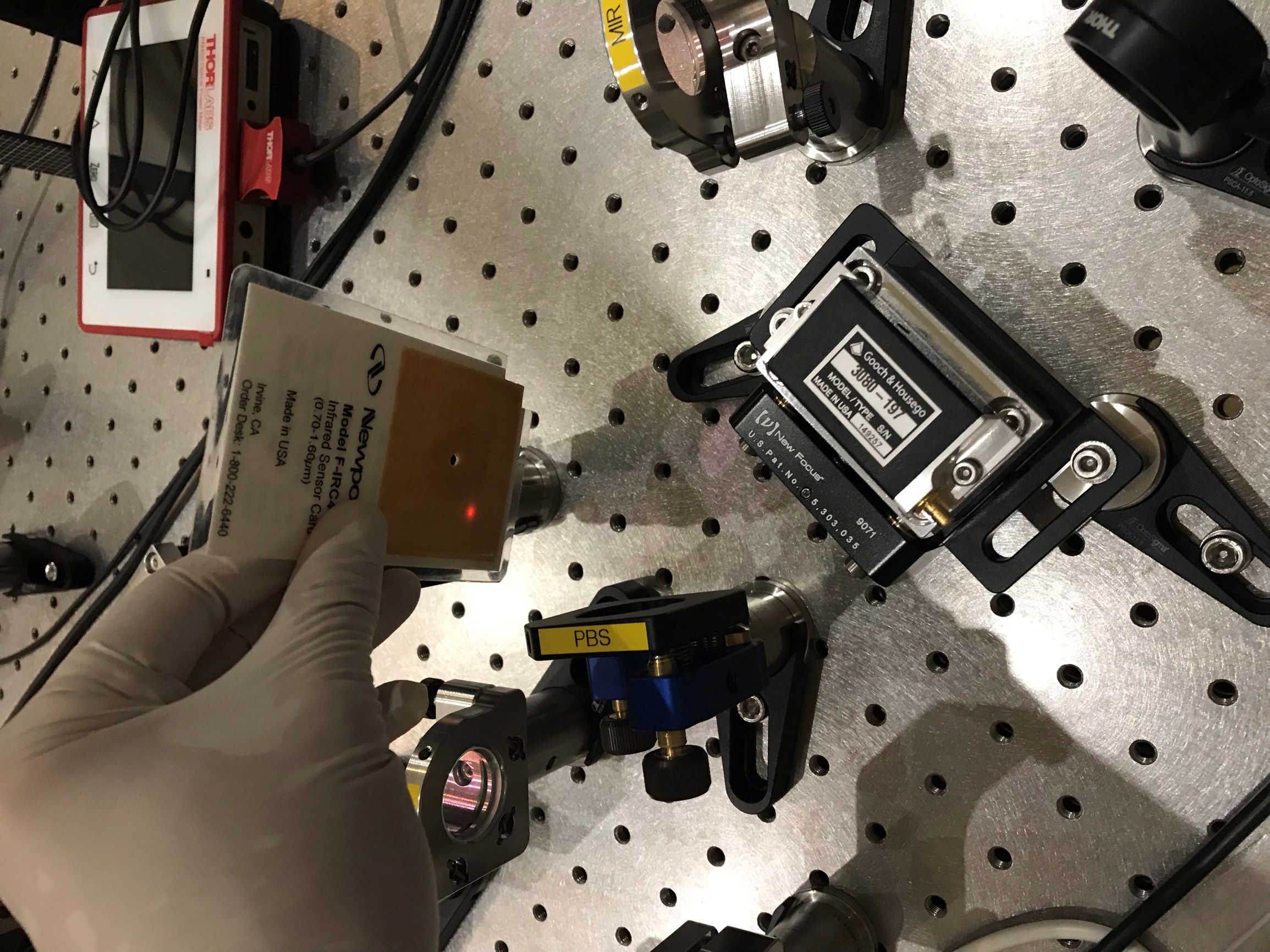
As we finished absorption and polarization characterizations of the ETMX spare mass, we exchanched it with the ETMY spare mass (see pictures below).
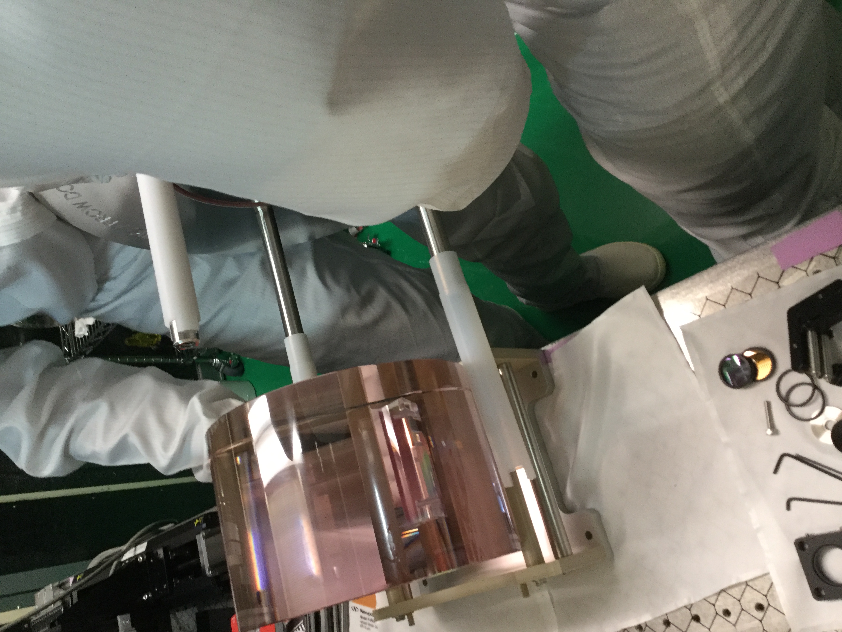
We tried a kind of new technique for making the exchanging procedure a bit more easier and safer. Therefore, we made use of the holding-structure of the container where the mirror-substrates are transported. We found that we can use those structures to flip the substrate in a horizontal position (which is required for the measurements) and to put it directly on the sample-holder which coincidentally fits very well to these holding-structures.
That way works also vice-versa.
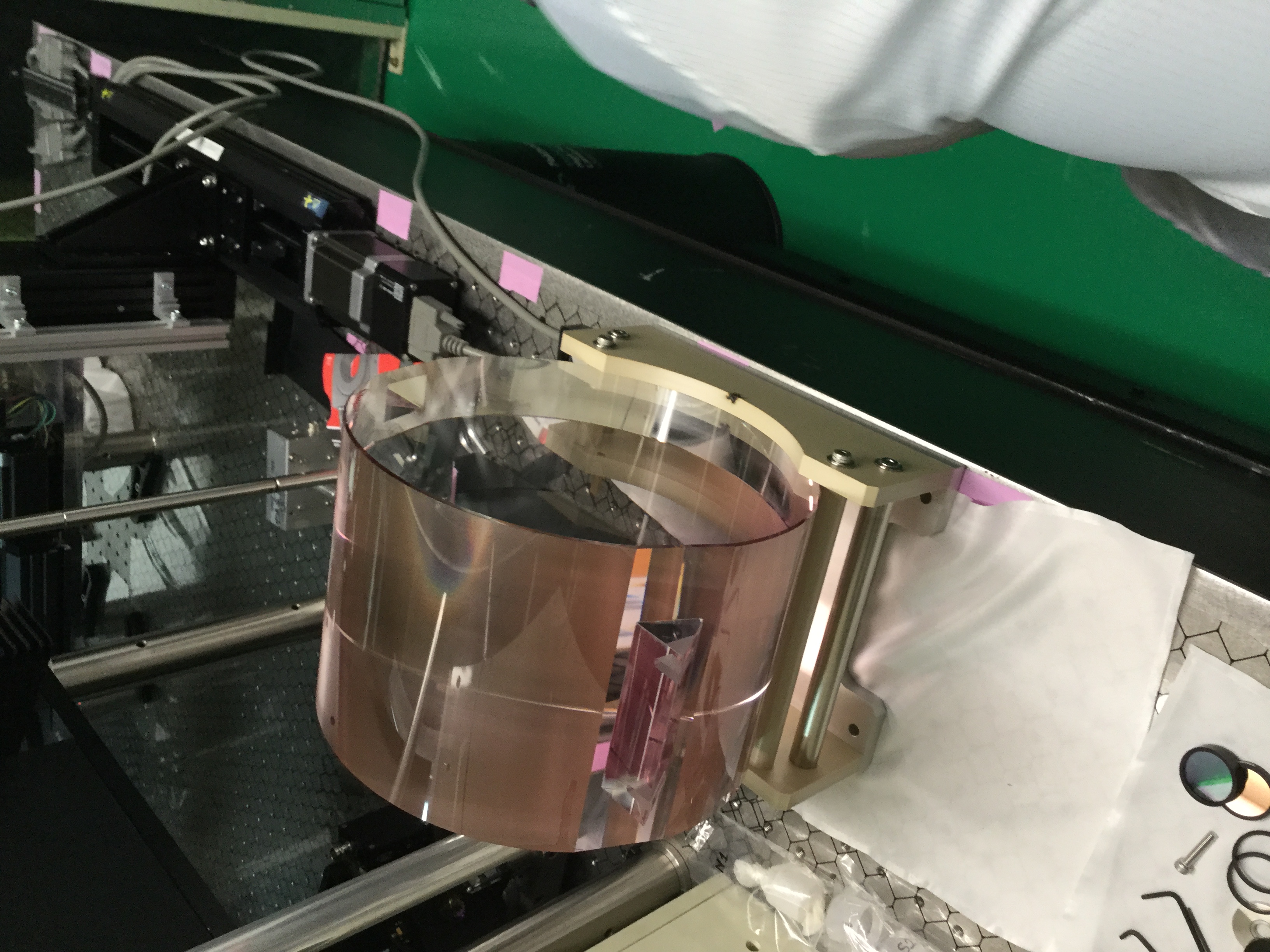
In addition, we recognized that both substrates indeed have a mark (probably) pointing to the thicker side of their wedges.
However, we found that this mark is on different sides for ETMY and ETMX (see last pictures).
Yuhang and Aritomi
Yesterday, we tried to put ND filter so that we could characterize the squeezing level.
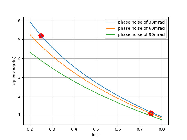
We put ND-0.3, which is corresponding to 0.5 loss.
When we were measuring, we were sending 40mW of green. From the measurement of yesterday, we could know the squeezing level we are sending is 13dB. By using this squeezing level, I made the plot of squeezing level change curve. The x-axis variables in the plots is losses. And there are three curves for different phase noise level.
The measurement result of squeezing corresponding to different losses is
| loss | squeezing level |
| 0.25 | 5.2dB |
| 0.75 | 1.2dB |
From this plot, it seems elog 1523 result is reasonable.
[Aritomi, Yuhang]
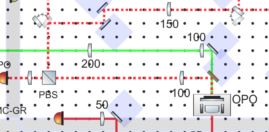
We measured loss of each optics between OPO and homodyne BS. We put BAB on resonance of OPO by hand and measured power. The result is as follows.
| position | power (uW) |
| after OPO | 231 |
| after dichroic mirror | 222 |
| after 100mm lens | 220 |
| after PBS | 219 |
| after 3 mirrors | 219 |
| after 150mm lens | 216 |
| after HWP | 215 |
| before homodyne BS | 215 |
Loss between OPO and homodyne is 7%. 4% is from dichroic mirror and 3% is from two lenses. According to spec of dichroic mirror (HBSY11), reflectivity for s pol should be 99.3%. We can try to optimize the angle or try another HBSY11. Anyway we need low loss dichroic mirror and superpolished lenses.
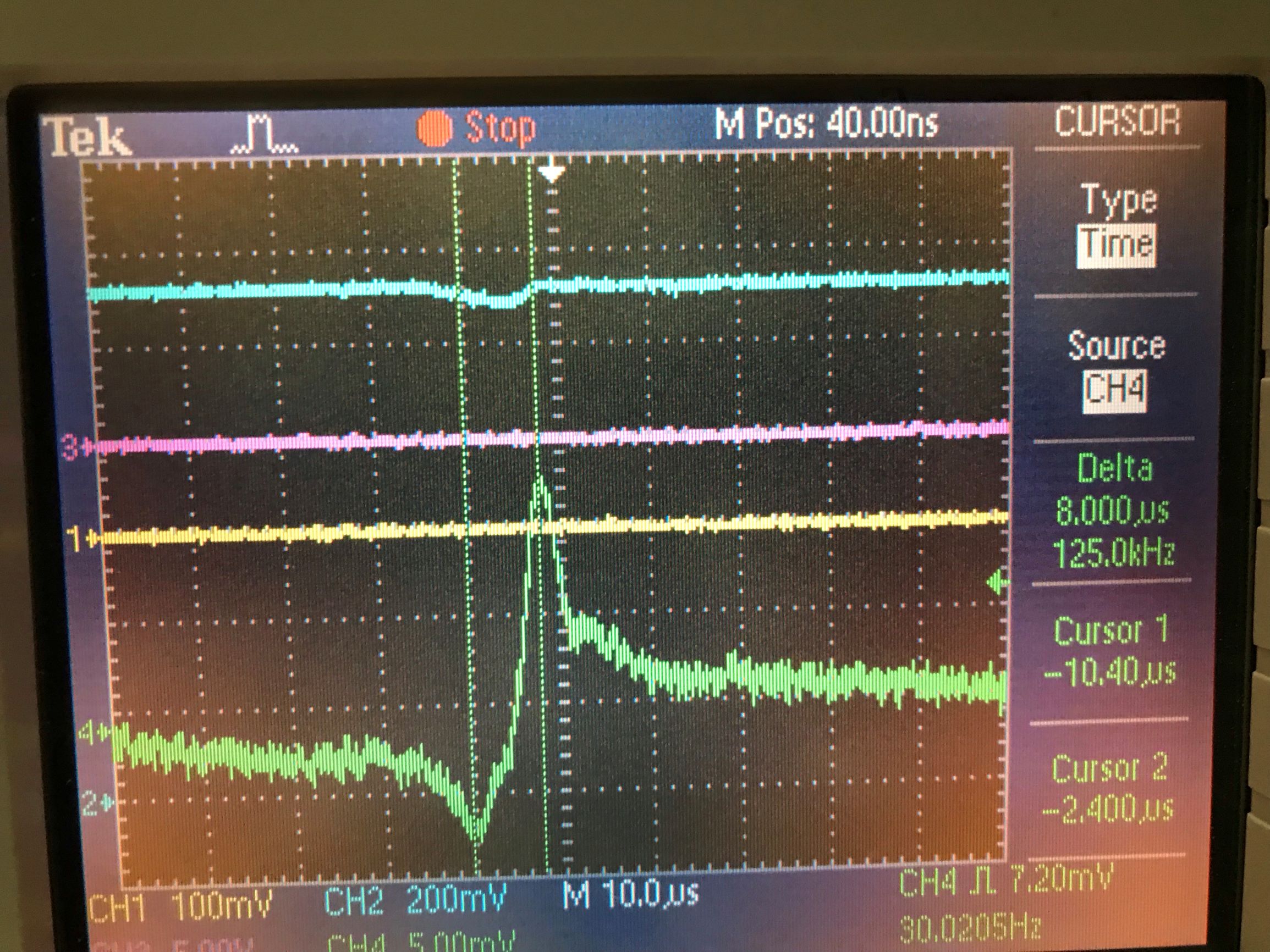
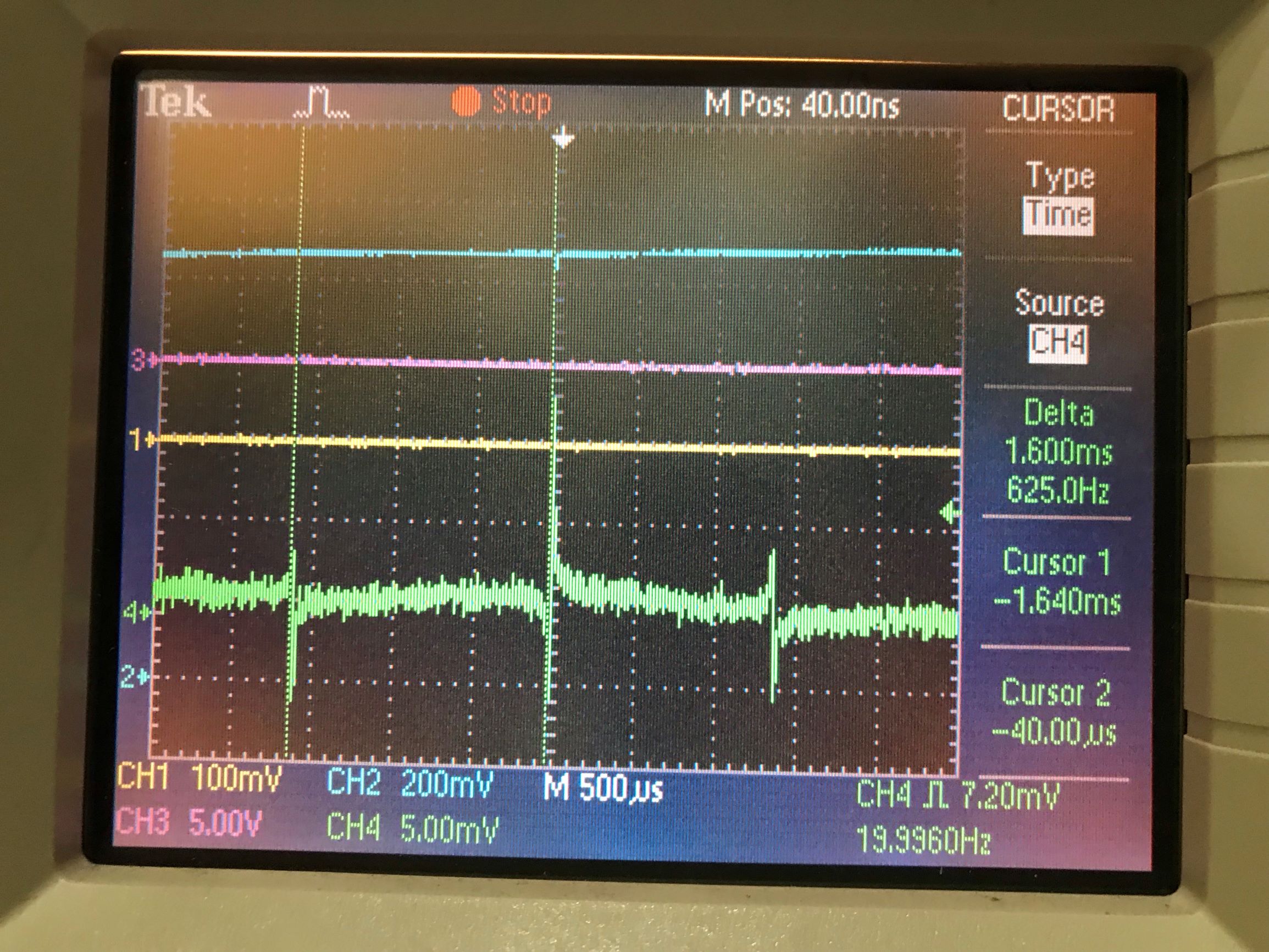
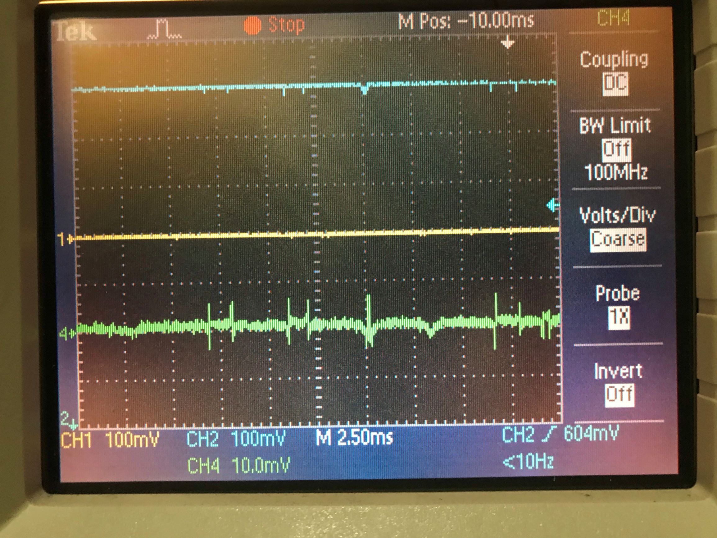
I measured the error signal of PDH lock as shown in attached pictures (green line).
Frequency scan was done with 20 Hz triangular wave (3Vpp).
Some details will be reported.
So far I have worked with closed 80K shield, and without most outer shield of cryostat chamber.
Today I closed the most outer shield using crane.
Actually, it did not improve the PDH lock stability.
The viewport window on the most outer shield is detached in order to avoid scattered light.
So this may cause acoustic fluctuation.
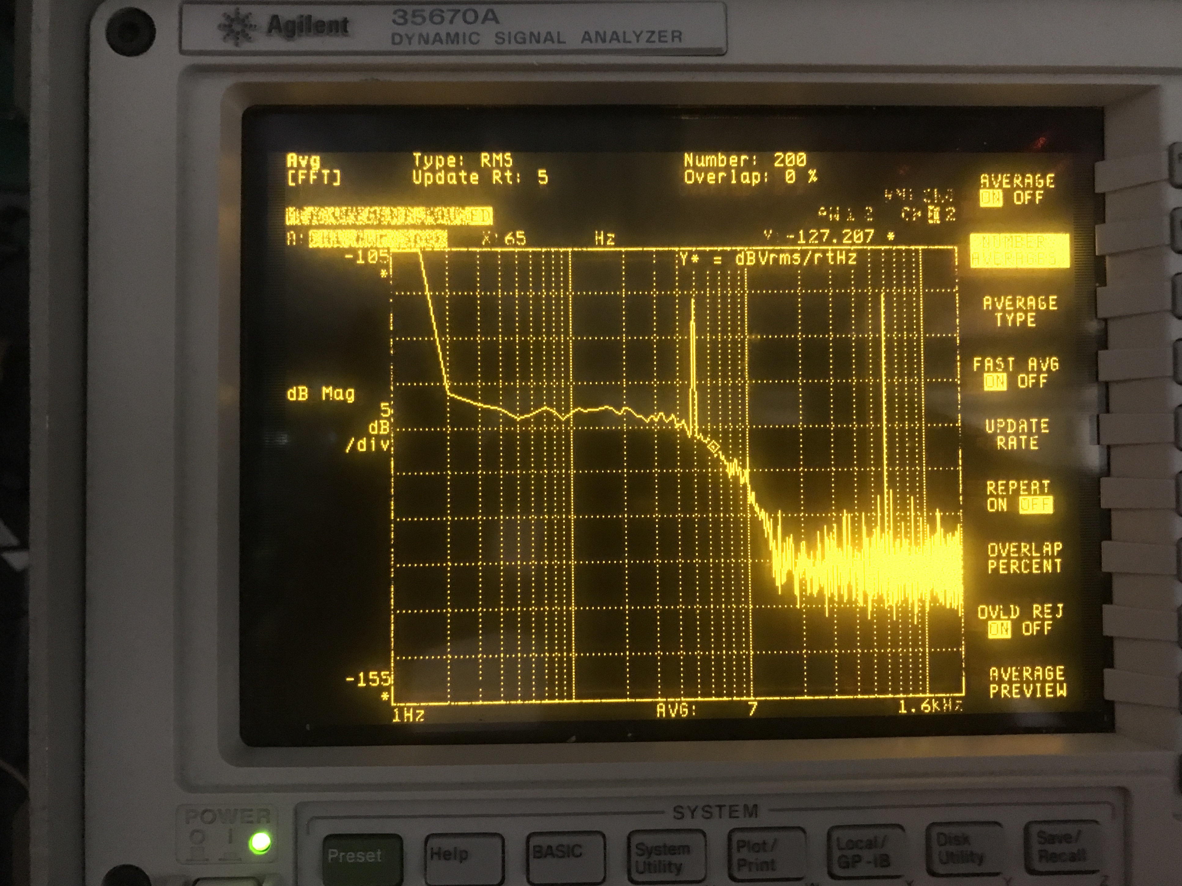
We often have large bump in shot noise spectrum like an attached picture. Note that squeezing path is blocked.
Yuhang and Aritomi
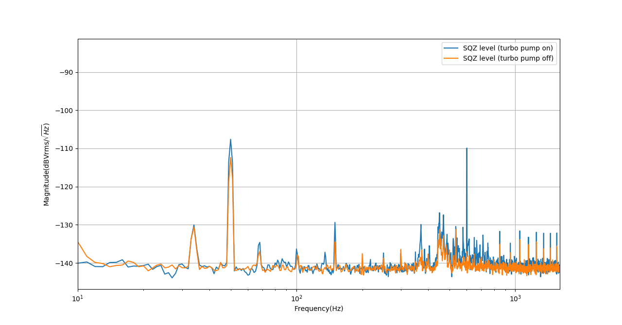
It seems that the turbo pump just gives us a narrow peak at 600Hz. The on and off of it doesn't change squeezing level.
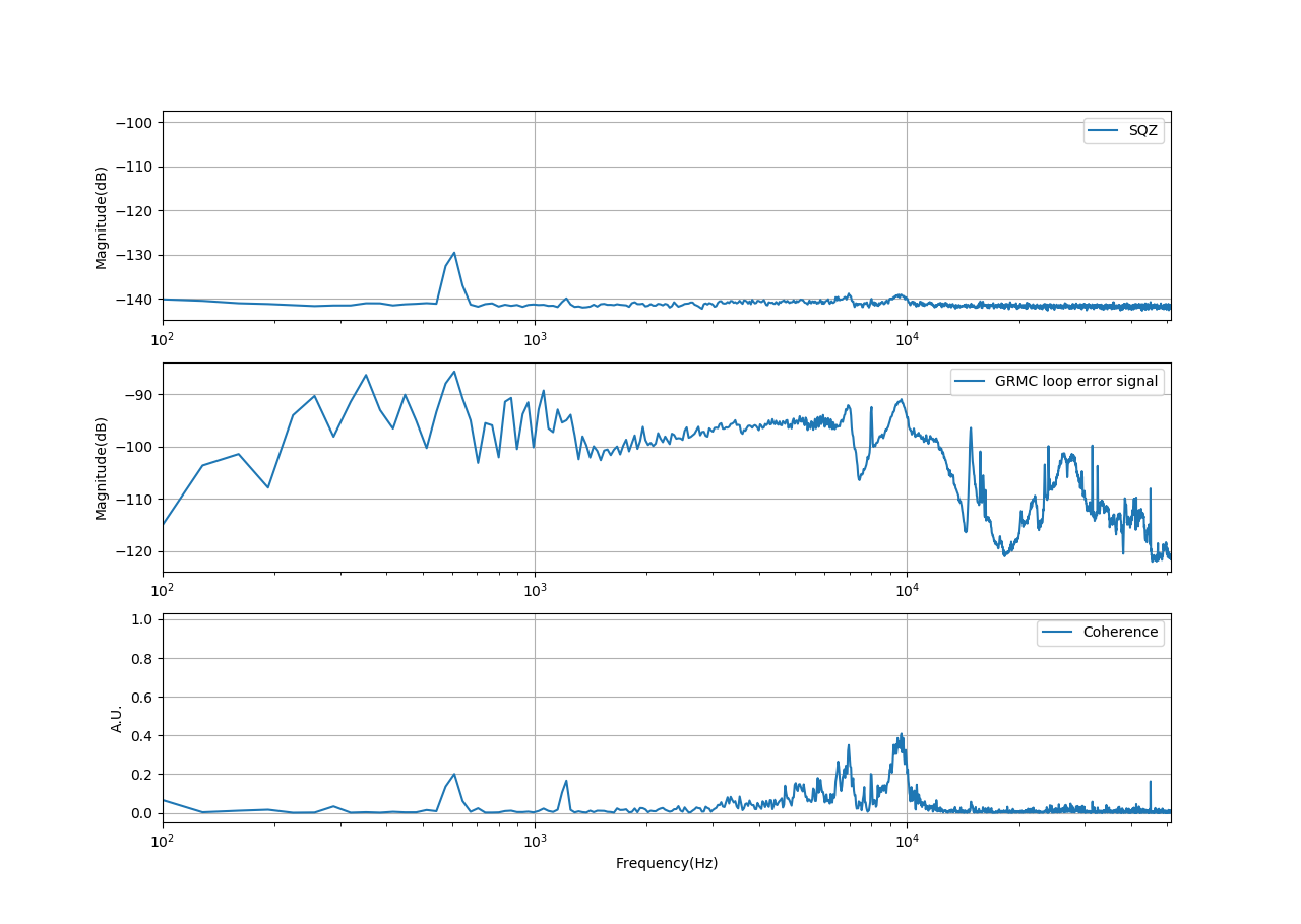
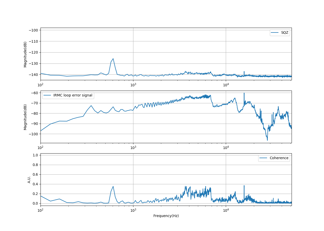
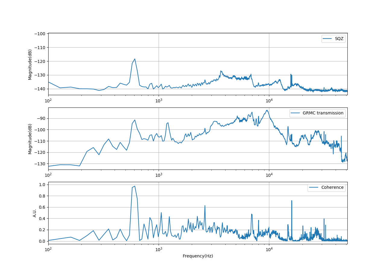
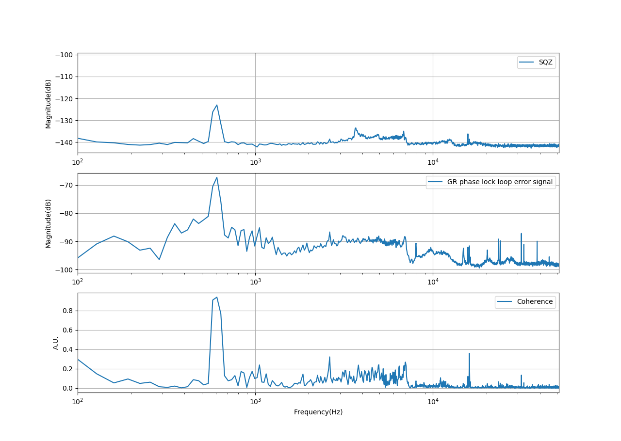
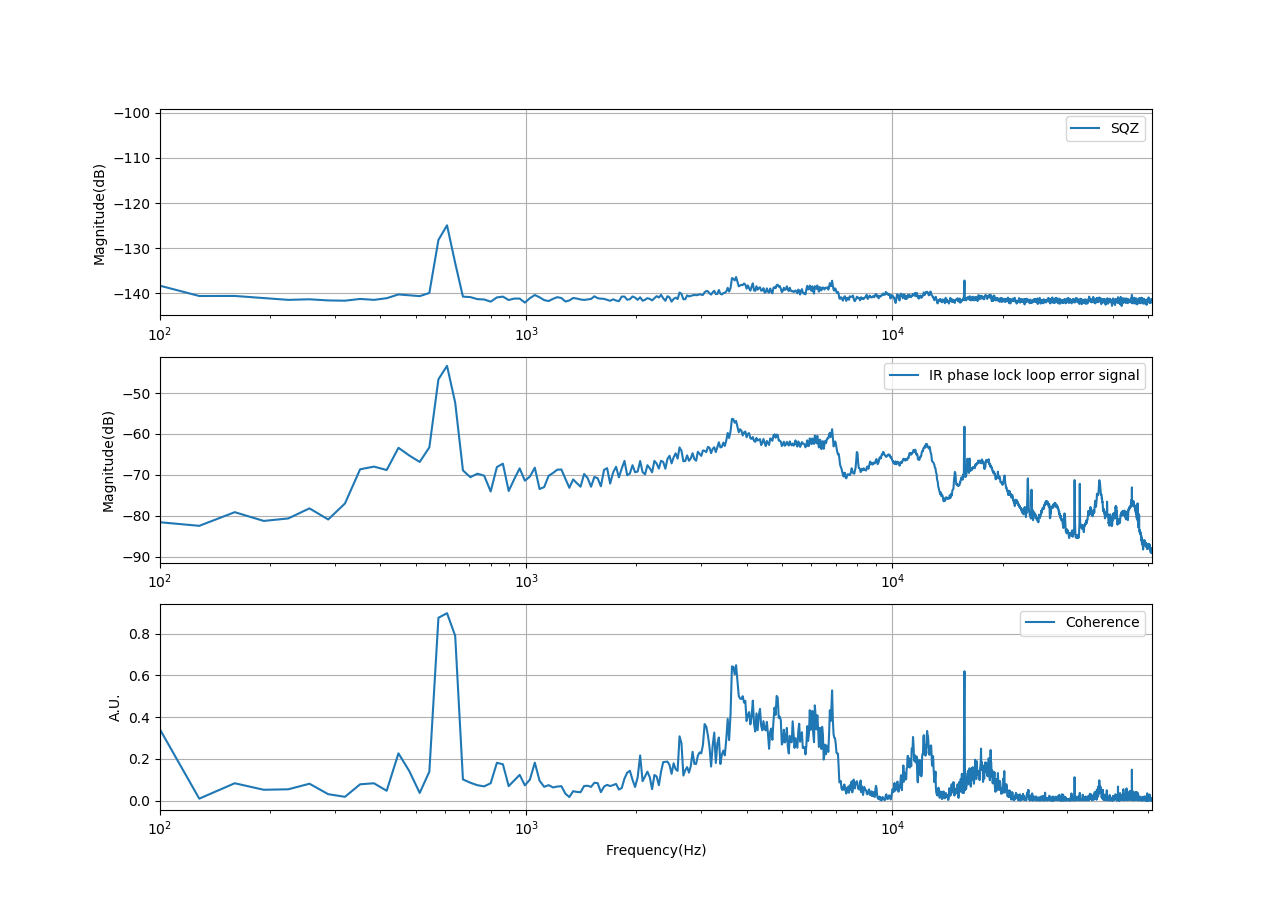
To see the contribution of noise at different frequencies, I performed the coherence measurement between squeezing and GRMC locking loop error signal/IRMC locking loop error signal/GRMC transmission signal/Green phase-locking error signal/IR phase-locking error signal.
The result is attached. From these results, we could have the following deduction:
- GRMC locking loop is contributing the noise at 9.5kHz and 6.9kHz
- The coherence between 3.7kHz and 6.9kHz shows up mainly in IR phase and IRMC locking.
- It seems IR phase noise and IRMC locking loop has strong coherence. So I think we can improve IR phase behavior by improving IRMC locking.
- 600Hz noise doesn't show up in the IRMC and GRMC locking loop.
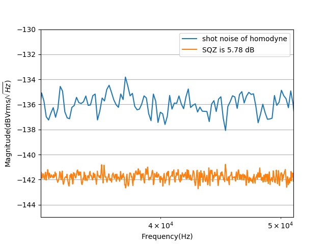
- Sometimes, the squeezing measurement is very good. For example, the one together with GRMC loop error signal. I attach the squeezing level at that time.
All the measurement is using averaging of the meachine of 200, I think we should use more average in the future.
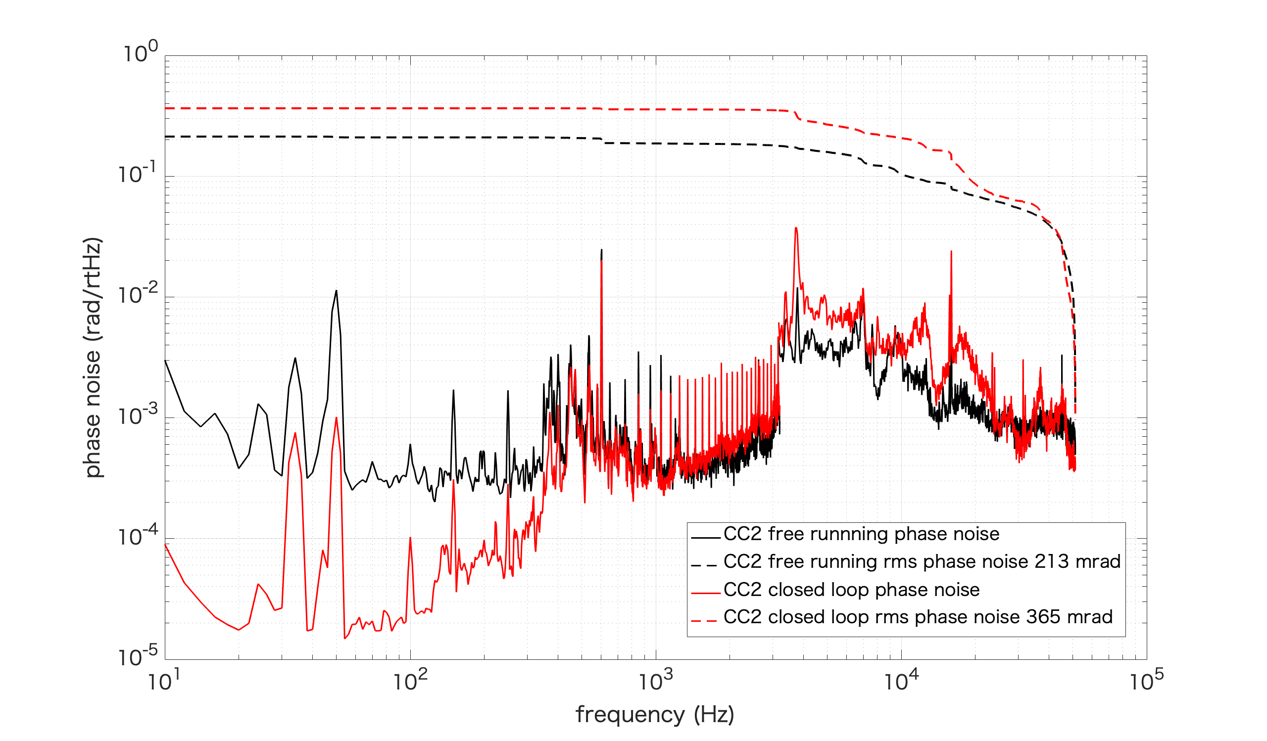
The large increase of phase noise above 300 Hz when the CC2 is closed (pic 3) is very strange and we need to investigate it. The loop should have a UGF of few kHz, but it doesn't seem to work correctly.
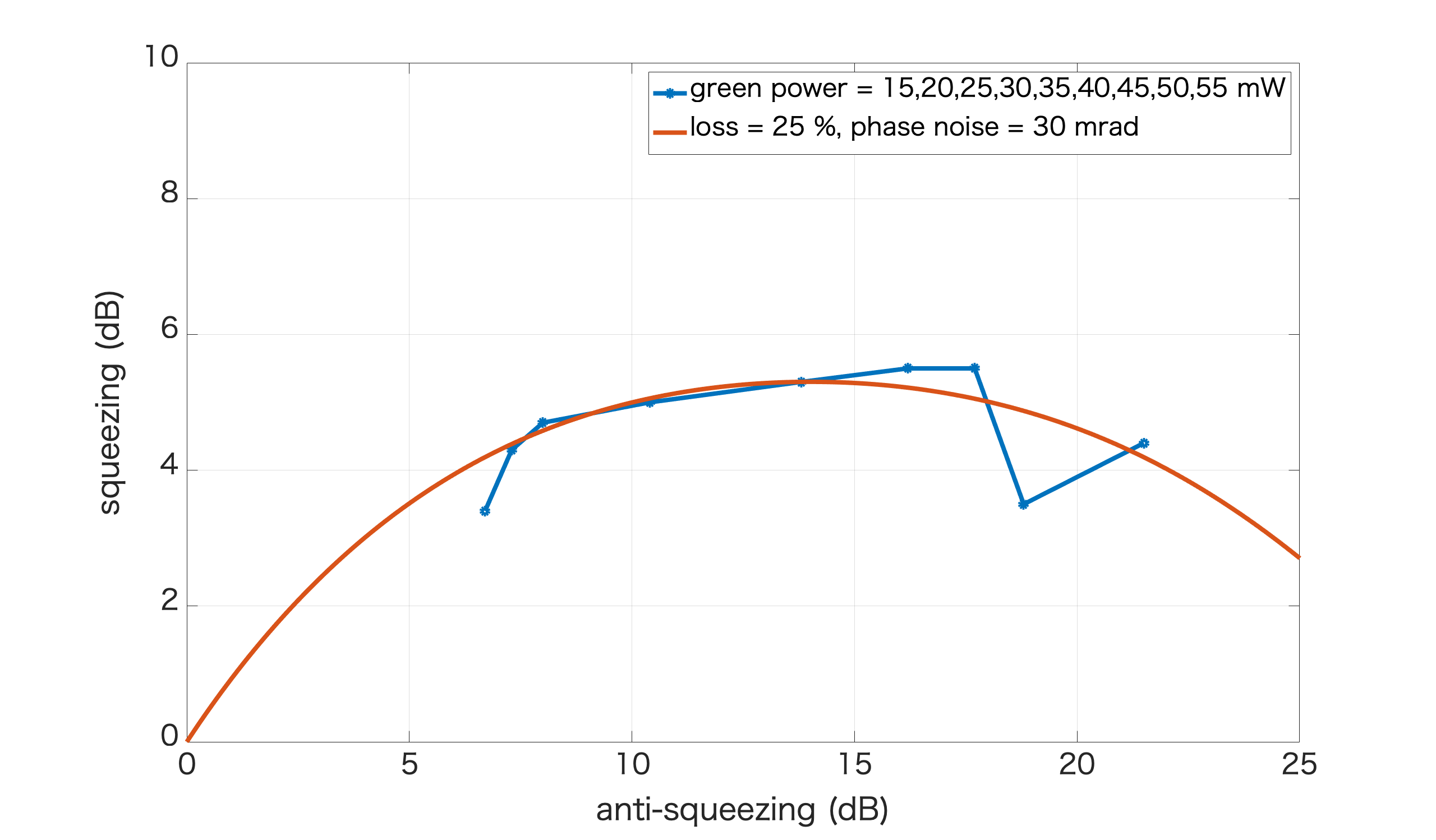
[Aritomi, Yuhang]
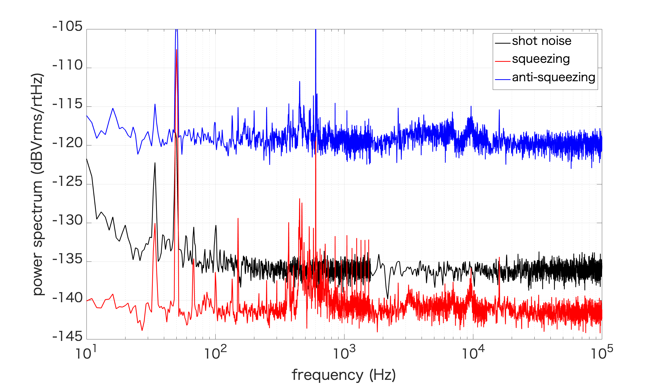
We measured squeezing and anti-squeezing with green power from 15 mW to 55 mW. Attached picture shows the result. Our case seems that loss is 25% and phase noise is 30 mrad. Note that this is not a fitting.
After this measurement, we checked visibility and found that visibility is 0.935 which means loss is 12.6%. (Note that when we calculated visibility, we didn't consider DC offset of PD. Visibility should be higher than this.) Then we aligned LO and BAB and visibility became 0.973 which means loss is 5.3%. However, squeeze level didn't increase.
| green power (mW) | MZ offset | OPO temperature (kOhm) | p pol PLL (MHz) |
| 15 | 4.01 | 7.16 | 192 |
| 20 | 4.1 | 7.16 | 177 |
| 25 | 4.19 | 7.17 | 177 |
| 30 | 4.29 | 7.18 | 180 |
| 35 | 4.38 | 7.175 | 162 |
| 40 | 4.5 | 7.175 | 150 |
| 45 | 4.58 | 7.18 | 147 |
| 50 | 4.68 | 7.19 | 150 |
| 55 | 4.78 | 7.195 | 150 |
| 60 | 4.88 | 7.195 | 144 |
| 65 | 4.98 | 7.2 | 141 |
[Aritomi, Yuhang]
Recently we turned off lasers when we leave. We accidentally kept lasers ON from last Friday and today we found that squeezing spectrum is very flat and phase noise is much less (attached pictures). Green power is 40 mW and error signal of CC1 and CC2 is 76 mVpp and 120 mVpp. Phase noise is smaller almost by a factor of 10. We guess large phase we had so far is due to unstable lasers. When we achieved good squeezing in May, lasers were always ON. We'll keep lasers on and see what happens.

The large increase of phase noise above 300 Hz when the CC2 is closed (pic 3) is very strange and we need to investigate it. The loop should have a UGF of few kHz, but it doesn't seem to work correctly.
[Yuhang, Matteo, Eleonora, Miyakawa (remotely)]
Last Friday, just before going home, we noticed that the DGS system was not working anymore and no signal can be read from ADC.
This happend suddenly since we used it up to one hour before and it was perfectly working.
Since me and Matteo were doing some cabling around the rack at that moment, we suspected we had accidentaly disconnected some cable but after a carefull checking it seemed that everything was fine.
On Saturday I contacted Miyakawa-san which accessed remotely the PC and told me it seemed a timing problem. On Saturday afternoon and also this morning we have carefully checked the timing signal.
Following the advice of Miyakawa-san, we change it from square wave of +/-5 V to 0-5V. It didn't solve the problem.
We tried to restart the models and reboot the PC countless times.
I tried to use only one time adapter (and switch it from one to the other) to check if one of the two was broken, but it didn't solve the problem
I tried to double the amplitude of the timing signal, to disconnect and reconnect the cables between AA, time adapter and I/O chassis. It didn't change the situation.
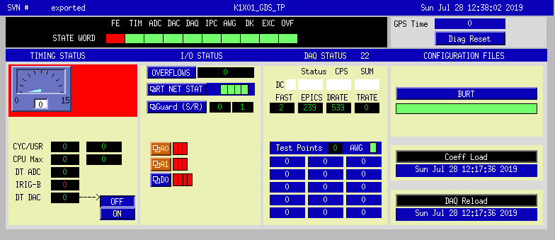
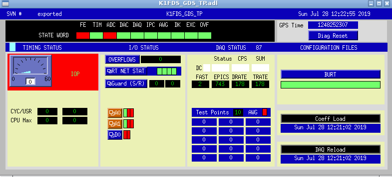
Pic.1 and 2 show the errors that appear in the DGS_TP screen for K1x01 (master model) and K1FDS (slave model), respectively.
We really need the help of an expert.
On top of that it seems the screen connected to the standalone doesn't work properly. Sometimes it gets black and we need to switch it on and off to recover it (but it usually last few seconds and then gets black again!)
[Matteo, Eleonora]
On Friday 19/08 we recived from Kamioka one AA module and two BNCtoDsub converters.
Last week we have installed the AA into the DGS rack and did some cabling from this rack to the cleenrrom as we blan to install the BNCtoDsub converters into the clean room rack.
We took a power supply from ATC and use it to power a KAGRA DC power strip (also taken from ATC). We use the strip to power all the two AA, the AI and the DAC dSub->BNC converter (not that ADC BNC-> dSub converters don't need power.)
We reorganize the cables behind the DGS rack to make them more tidy.
We also removed one ADC PCiexpress card from the new DGS computer (the one we couldn't make work) and installed it into the standalone PC we are currently using.
The standalone can host up to 4 card and we have currently installed two ADC an one DAC. The slots are piled up in vertical. From the bottom we have
1) ADC 1 (used for local controls)
2) ADC 2 ( not used, it will be used for AA signal)
3) DAC
4) empty
In the future we can decide to put another DAC or another ADC in the empty slot. According to Miyakawa-san all the possible combinations of 4 PCie among ADC and DAC are fine with the excepion of 4 DAC.
We took an additional timing adaptor from ATC which we used to provide the timing signal to the new ADC card.
We haven't tested the new ADC but the system seemed to work fine after these modifications. We didn't experienced any trouble until the failure of last friday (26/07).
I checked PDH error signal (green line) with low-pass filter.
Though the time resolution is higher than before, still the error signal is spike-ish structure.
This may be due to too high finesse of silicon cavity.
At this moment, I did not use frequency scan by laser PZT, but temperature fluctuation of laser induced frequency fluctuation.
Thus I could see error signal without scanning laser frequency.
It needs temp. control loop for stable lock.
Anyway, I will consider cotrol loops for TEM00 lock.
I tried to feedback a part of the PZT correction (sent to the main laser to lock it to the FC) to the end mirror. The goal is to reduce the cavity motion at the logitudial resonance frequency (around 1Hz), acting on the mirror in order to reduce the correction sent to the laser. In fact in this region, the correction increases the frequency noise of the main laser, inducing higher PLL noise.
The PZT correction is taken from the channel "pzt mon" of the rampeauto (which is 100 times smaller that the real correction), it is sent to the ADC of the DGS where it is digially filtered and then the correction is summed to the one already sent to the end mirror coils (from anguar damping).
We observed that the signal seen by DGS has a very strong 50 Hz, which is not present when locking at it with the oscilloscope.
In order to select the part of the spectrum aroun the 1Hz, I used a filter like this:
| Freq (Hz) | Q | |
| zero | 0 | simple |
| pole | 1 | simple |
| pole | 20 | simple |
| pole | 20 | simple |
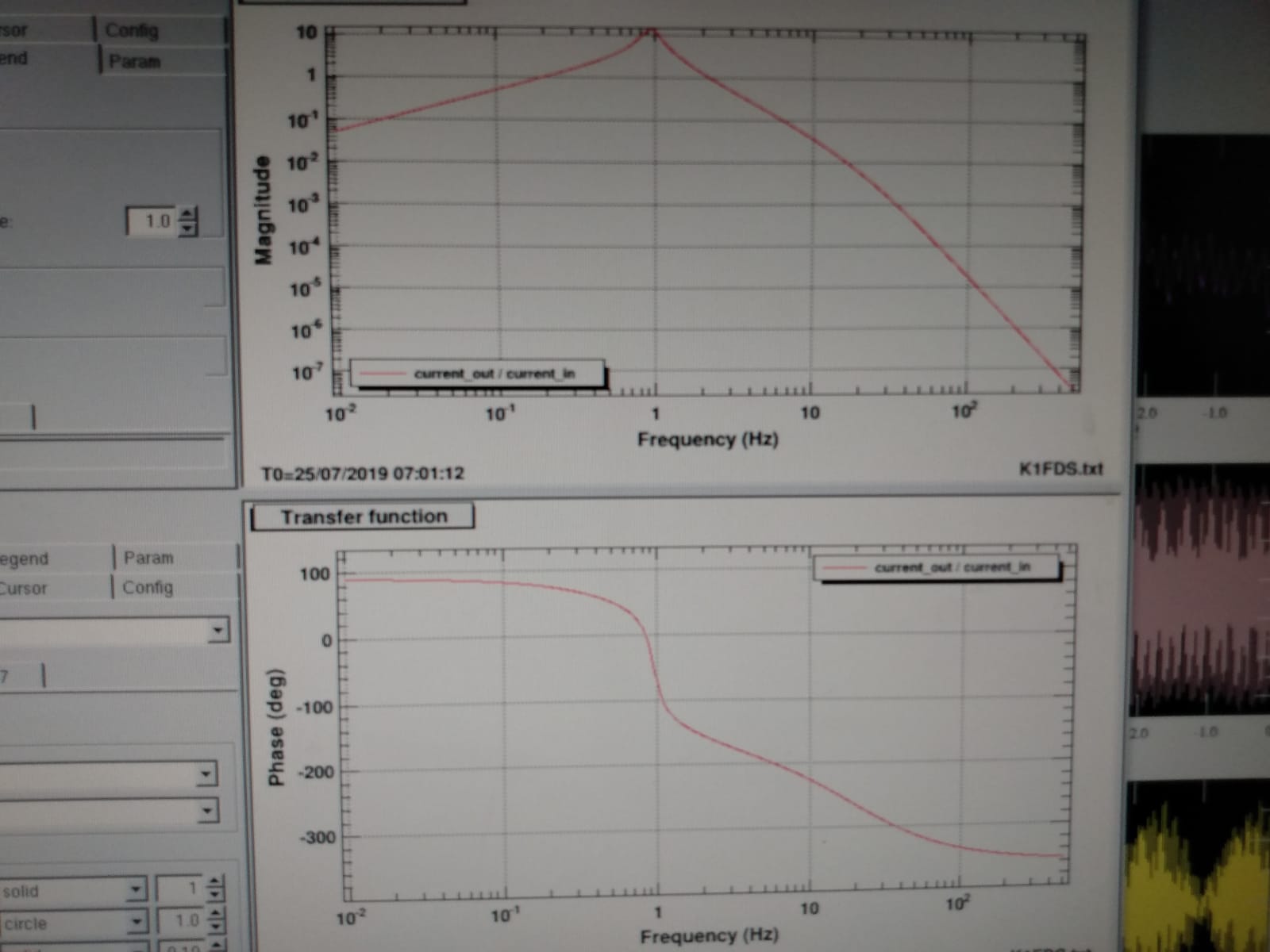
The simulated openloop TF is shown in pic1. Where as a mechanical TF I used the one measured in entry #1506
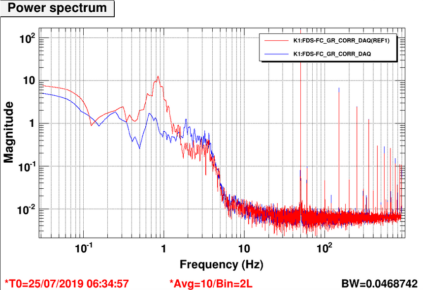
Pic.2 show the spectrum of the PZT correction with (bue curve) and without (red curve) test mass feedback engaged. It can be seen that the correction to PZT is reduced by a factor ~10 in the 1Hz region when the feedback is engaged (blu curve).
To be done:
- Amplify the signal before the ADC with a stanford to better exploit the ADC dynamics.
- Check the RMS improvement and optimize the correction filter (an overshoot is now visible at 2-3 Hz).
- Add a notch filter to avoid feeding back the 50 Hz and to be able to check the signal improvemt in time (currently it is fully dominated by the 50 Hz).
- Check wheather the PLL noise is reduce when the loop is engaged.
[Aritomi, Yuhang]
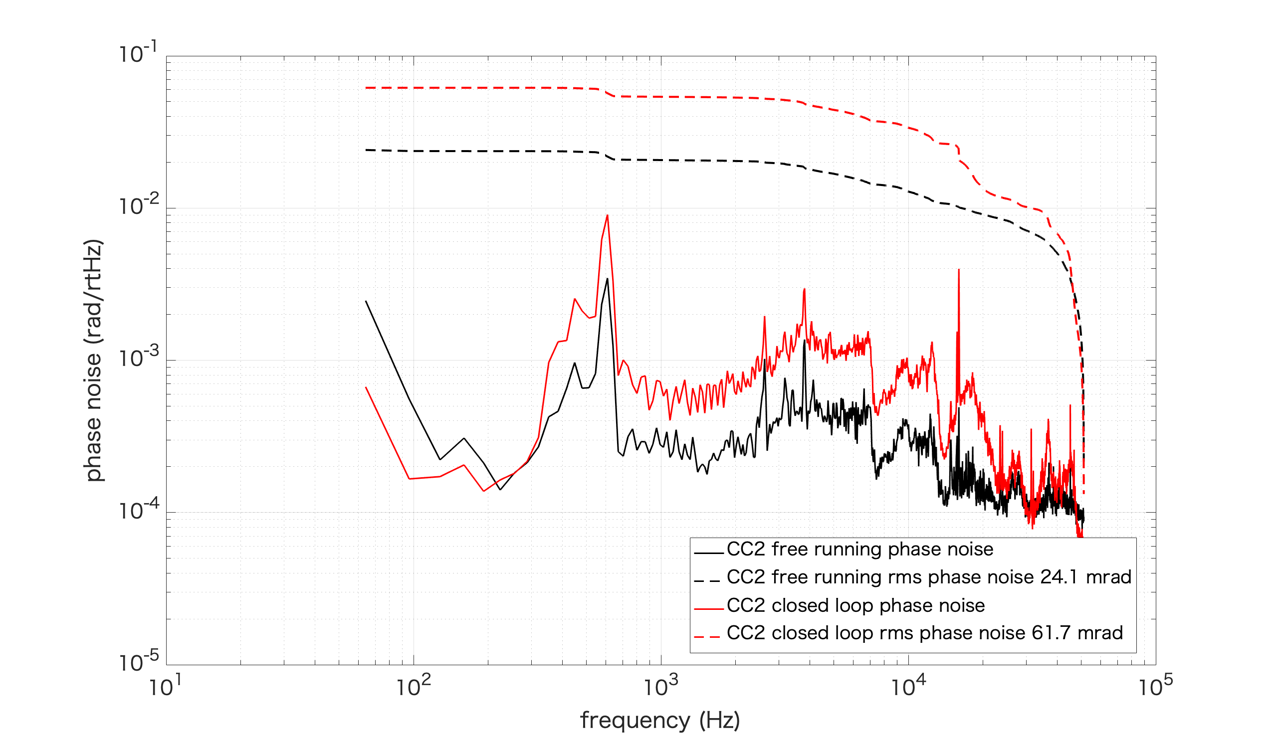
First we moved position of green phase shifter closer to GRMC since effect of misalignment of green phase shifter was large due to rubber and also there was no space to put additional clamp to fix green phase shifter.
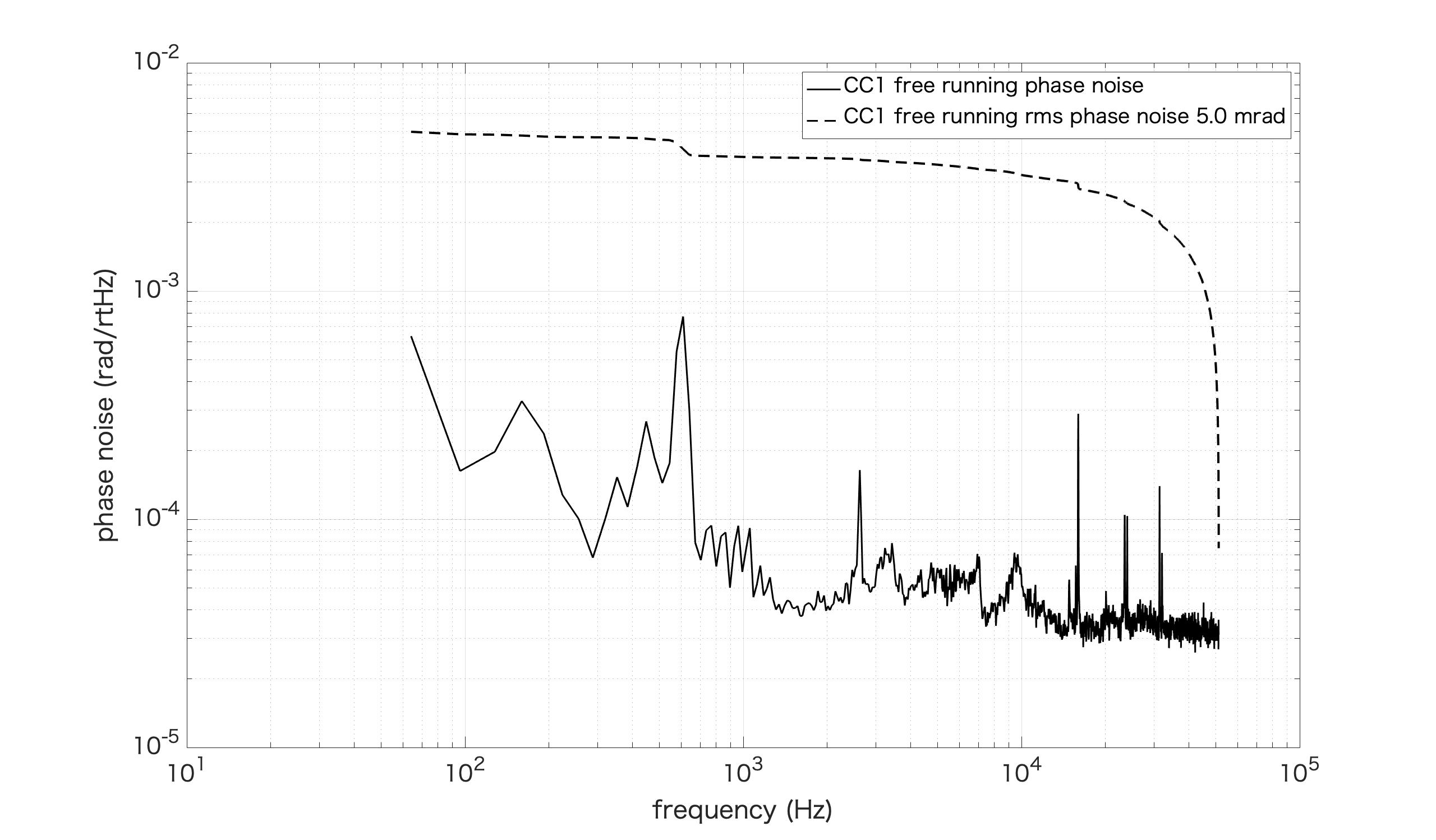
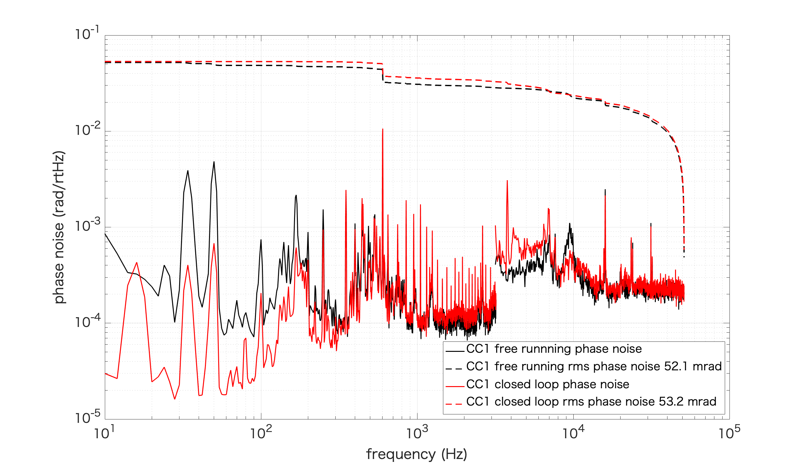
Then we measured free running and closed loop phase noise of CC1,2 (attached pictures). We measured EPS2 of servo as error signal. Note that EPS2 of servo is larger than real error signal by a factor of 15.
As you can see, phase noise above 400Hz is very large and rms phase noise is mostly accumulated at high frequency where phase noise is not suppressed by CC loop. When we close the CC loop, phase noise at high frequency becomes larger and rms phase noise becomes even larger. This measurement is consistent with recent noisy squeezing measurement.
So far, I installed an AOM and some mirrors which consist double pass AOM configuration.
I install a lens in order to avoid clipping at AOM.
Then I adjusted the alignment, and double-passed light can be picked off by PBS now.
Although I have not driven the AOM, the first rough alignment has been done.
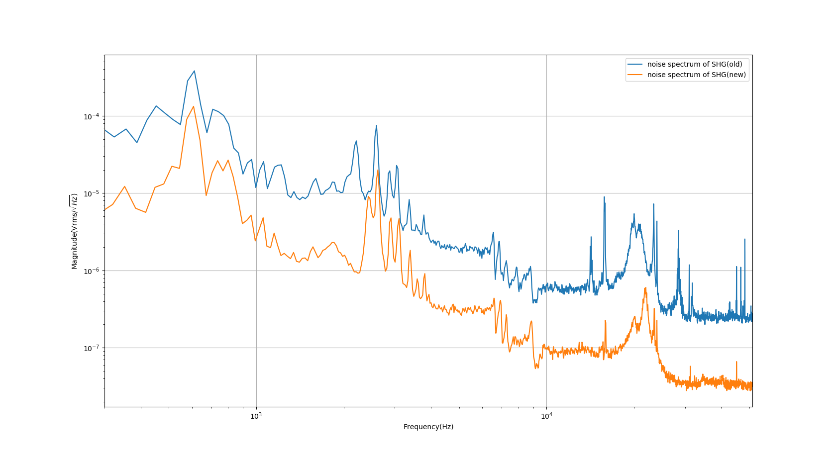
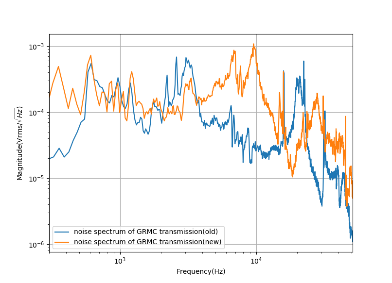
Here I attach the measurement of SHG and GRMC transmission noise spectrum.
The difference is I measured the noise spectrum of SHG transmission at a wrong place. (Actually, I was measuring the locking noise of SHG in the entry 1501)
However, we really have a worse GRMC transmission noise. Especially, there are peaks from the 4-10kHz region. They are responsible for the region where we have more noise in the squeezing measurement.
I will try to understand why there is a factor between the old and new measurement.