NAOJ GW Elog Logbook 3.2

| DDS1 | |||
|---|---|---|---|
| channel | function | frequency | phase |
| CH0 | EOM SHG/IR-MC | 15.2MHz | 0deg |
| CH1 | SHG + IR-MC demod | 15.2MHz | 0deg |
| CH2 | EOM OPO | 87.6MHz | 0deg |
| CH3 | OPO demod | 87.6MHz | 135deg |
| DDS2 | |||
|---|---|---|---|
| channel | function | frequency | phase |
| CH0 | EOM FC/GR-MC | 78.0MHz | 0deg |
| CH1 | FC demod | 78.0MHz | ~ |
| CH2 | GR-MC demod | 78.0MHz | 60 deg |
| CH3 | |||
As entitled.
| CHANNEL NAME | AMPLIFICATION |
| AOM FC | 37.3dB |
| EOM SHG+MCIR | 20.8dB |
| EOM FC+MCGR. | 20.8dB |
| EOM OPO | 20.9dB |
| DEMOD SHG | 13.6dB |
| DEMOD MCIR | 13.5dB |
| DEMOD FC | 13.6dB |
| DEMOD MCGR | 13.7dB |
| DEMOD OPO | 13.7dB |
| DEMOD CC | 14.1dB |
| PLL OPO lenght | 18.8dB |
| PLL CC | 18.7dB |
Labels with the amplification values have been applied to all the channels.
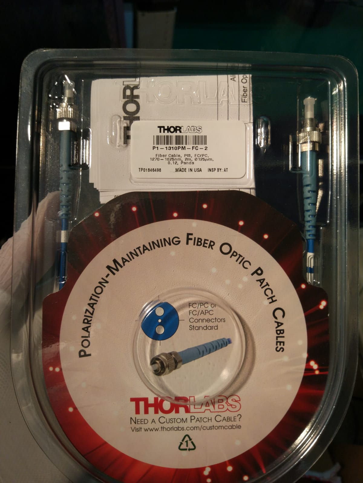
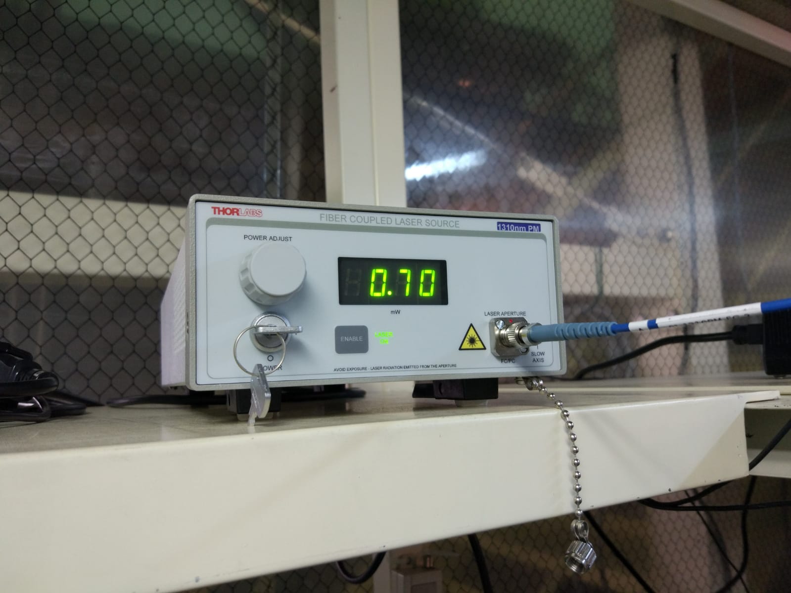
The new laser Thorlabs S1FC1310PM was delivered today together with the optical fiber.
I replaced the demo laser with the new laser. (the demo laser was the same model).
I switched it on, it works, and the alignment looks fine.
The demo is ready to be shipped back to Thorlabs.
[Matteo, Eleonora, Aritomi]
Memo of parameter for the lock of the PLL (no green injection, only p-pol and BAB).
T_OPO = 7.038kOhm
ppol PLL LO freq = 130MHz
DDS3_ch0 = 65MHz
PLL R = 1
PLL N = 2
Reference freq = 65MHz
Charge pump setting 1 = 1.875mA
[Matteo, Eleonora, Aritomi]
The gain of the SR560 used for the OPO lock was changed from 5 to 20. The lock seems more stable now.
I switched on everything after the last power shut down.
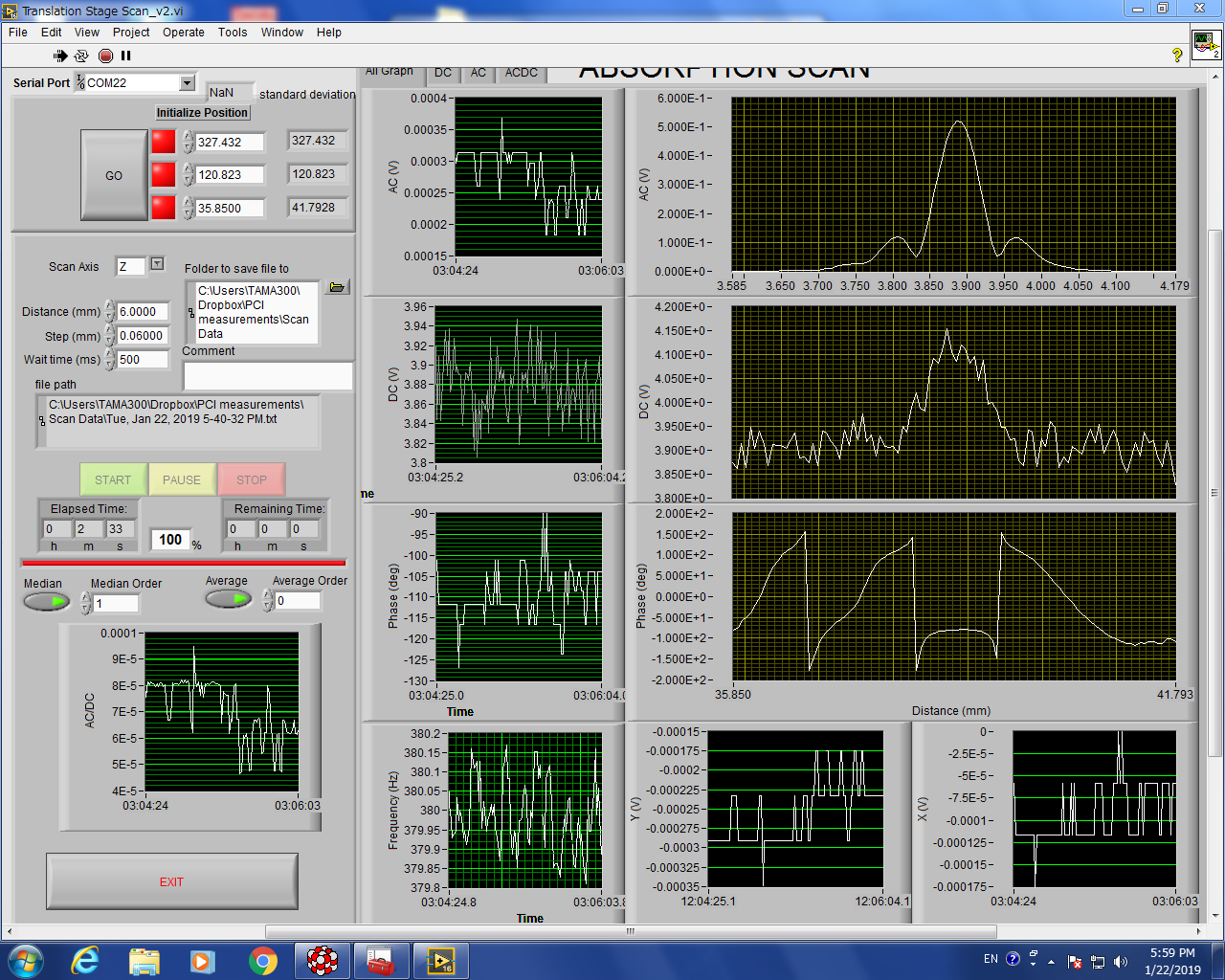
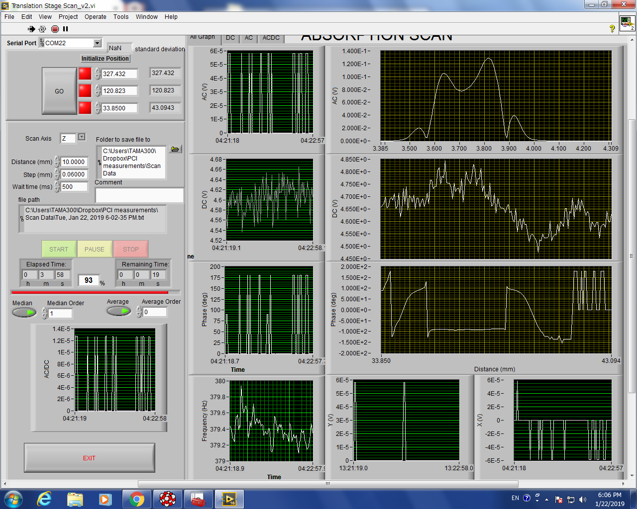
I re-aligned the HeNe probe with the surface reference sample, and made a calibration scan, then, a calibration scan of the bulk reference sample.
The pump power is 30mW, so,
for the bulk: R = 0.08/4.75/0.03/1.04 = 0.54 cm/W
for the surface: R = 0.52 /4.1 /0.03 / 0.2 = 21.1 W-1
[Matteo, Eleonora]
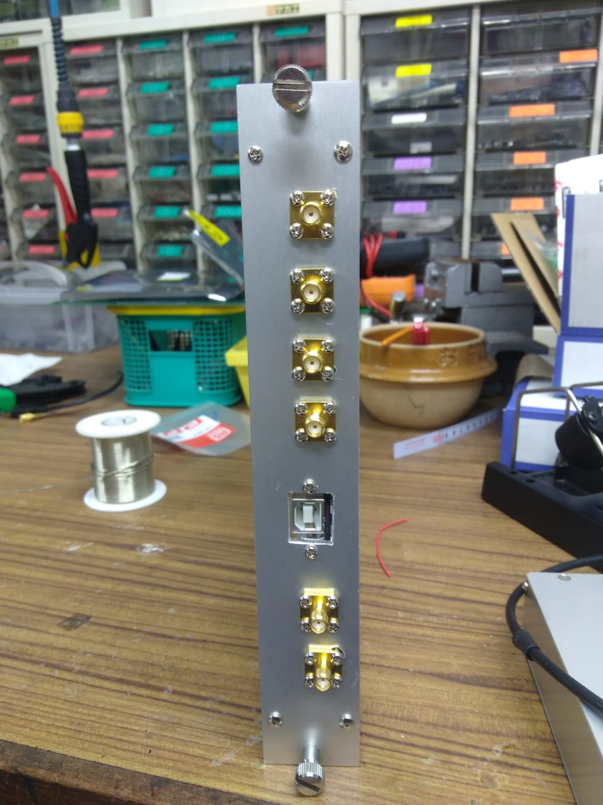
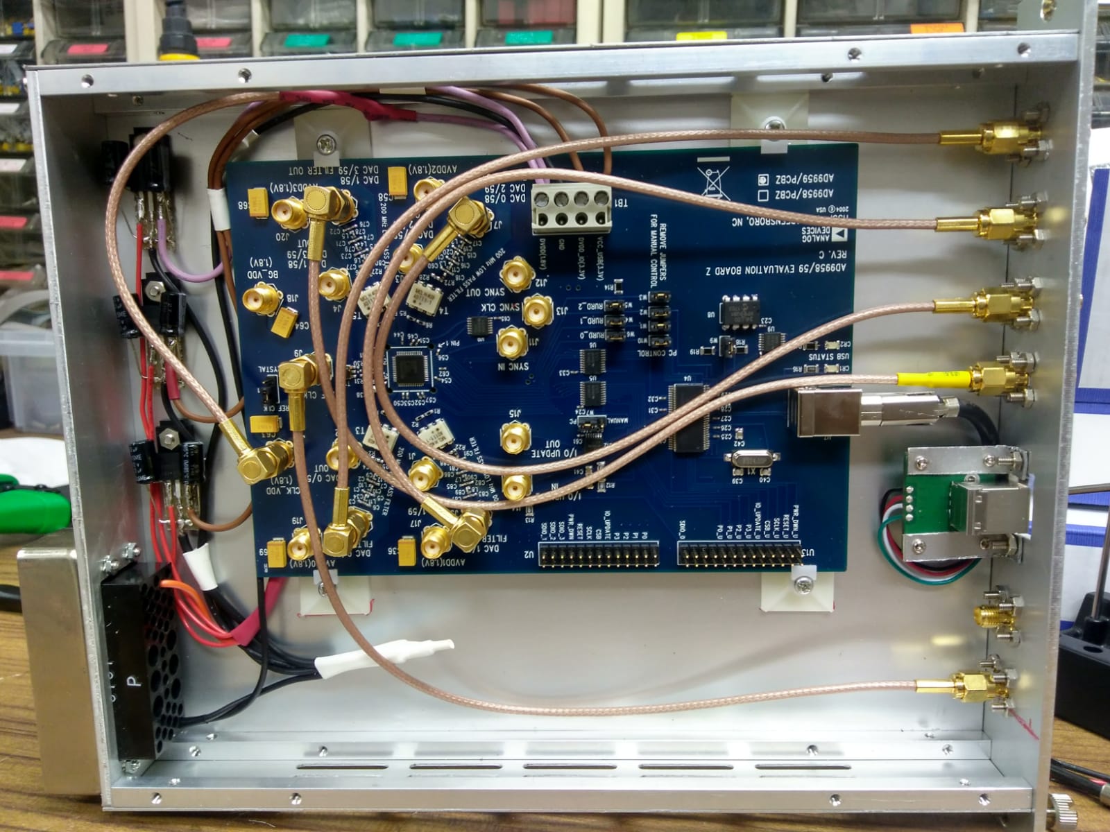
We have assembled an additional DDS board able to provide four RF signals.
For the assembly, we took as a model one of the two boards already realized at ATC. Pictures of the new board are attached.
The board have been tested and seems to work well.
Now we have three DDS boards providing four channels each. Here the "final" channel assignment we plan to have:
BOARD 1
| DDS1 | |||
|---|---|---|---|
| channel | function | frequency | phase |
| CH0 | EOM SHG/IR-MC | 15.2MHz | 0deg |
| CH1 | SHG + IR-MC demod | 15.2MHz | 0deg |
| CH2 | EOM OPO | 87.6MHz | 0deg |
| CH3 | OPO demod | 87.6MHz | 135deg |
| DDS2 | |||
|---|---|---|---|
| channel | function | frequency | phase |
| CH0 | EOM FC/GR-MC | 78.0MHz | 0deg |
| CH1 | FC demod | 78.0MHz | ~ |
| CH2 | GR-MC demod | 78.0MHz | 60 deg |
| CH3 | |||
[Aritomi, Yuhang]
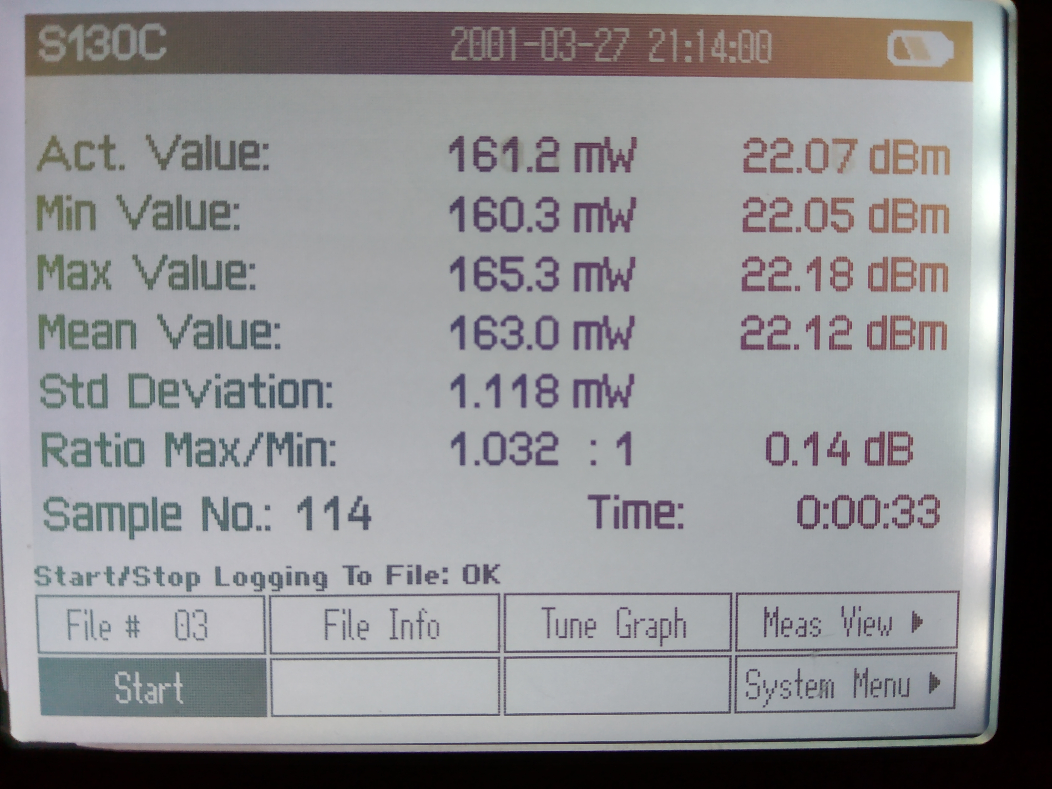
We recovered the BAB alginment into OPO after removing second FI. The stability is also measured in the infrared path. As shown in the attached figure 1, it is quite stable(the fluctuation is only within 1%). From the experience, the stability is related to how well we align SHG. From the spectrum on the oscilloscpe we got after removing the second FI. And compare with the spectrum we got during Chienming is here. It is obvious that the alignment is worse than that time. So this stable infrared light is reasonable.
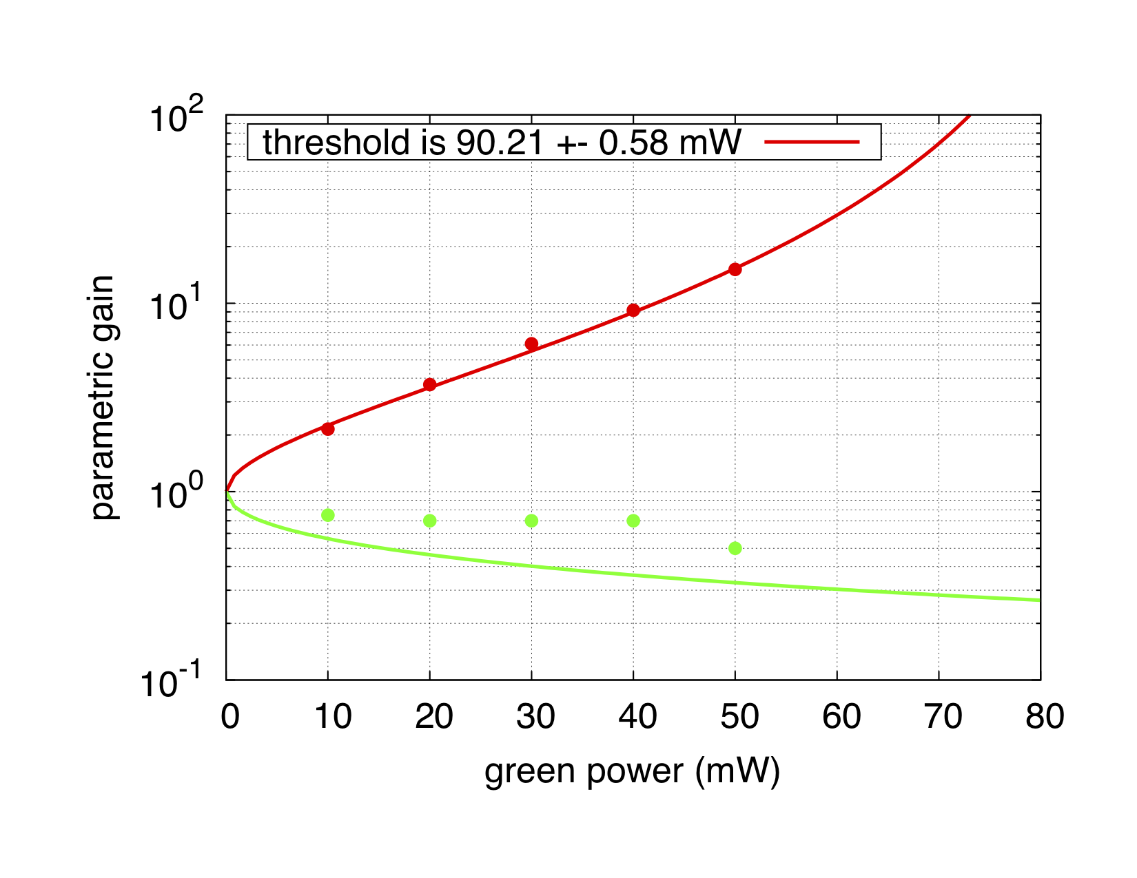
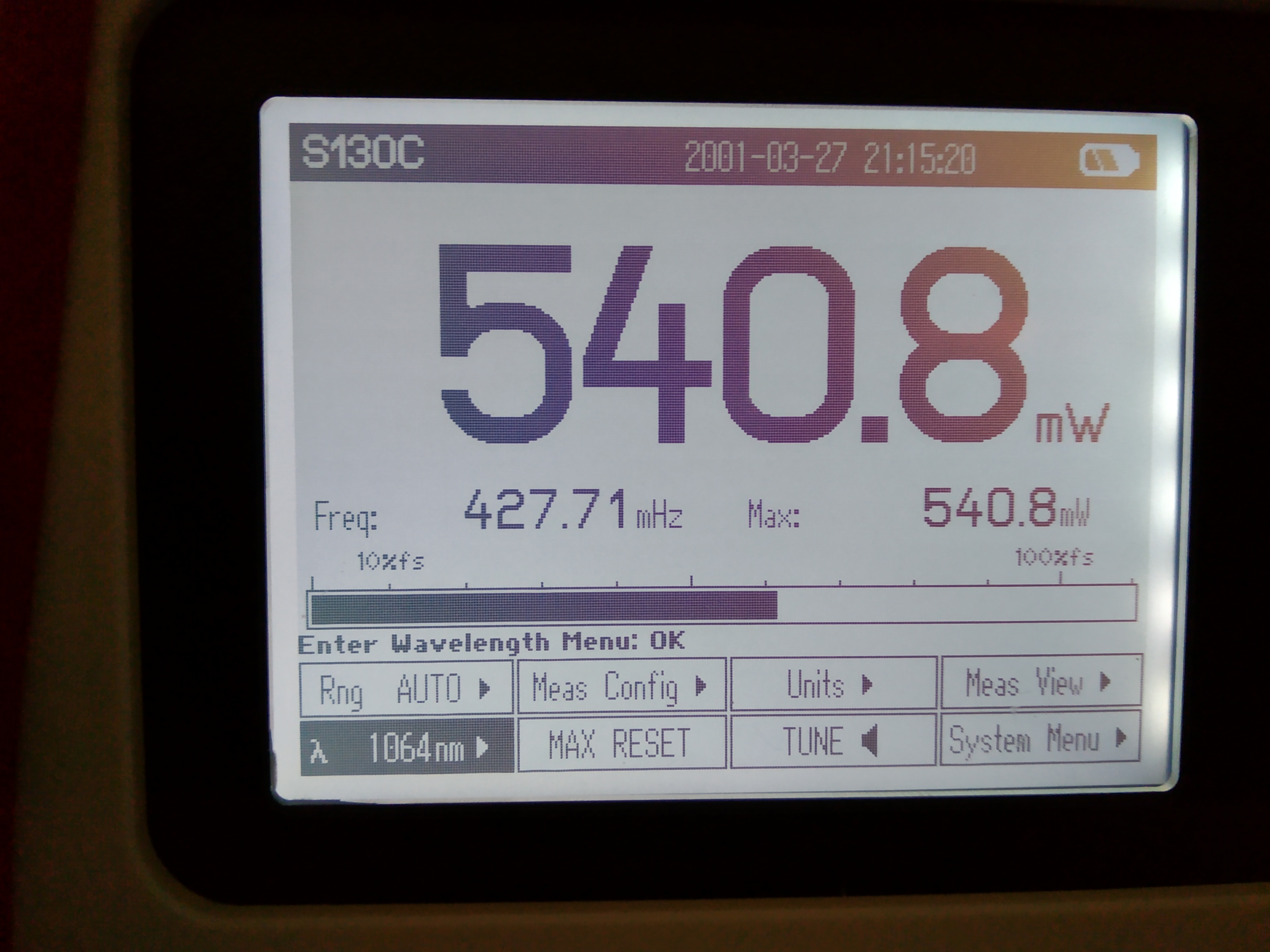
We also measured the green production efficiency, now it is 163/540.8=30%. This is lower than the effciency 35% when we have a better matching/alighnment. But still higher than the situation before Chienming came, at that time efficiency is only 20%. Although the efficiency is worse, but we have maximam 50mW going to OPO. While the threshold is 80mW for OPO. So we can use this power to observe a desirable level of squeezing. We can also increase the injection power to SHG if we want higher green power. So it should be fine with this alignment condition.
However, we found the parametric (de)amplification process has some abnormal behavior. If you check this video in the attached link, you can see the scanning peak has a roughly 50% of fluctuation(sorry I didn't take quite long time and this fluctuation doesn't have a clear frequency). And seems there are two peaks they are competing with each other. Sometimes, the pump goes into one. Sometimes the other. Actually after we realize this problem, we start to check the fluctuation of infrared and green. They are as good as before. We also checked if we have mode hop. Even it is clear form the SHG scanning that we don't have this problem. After trying to change the temperature, we didn't find mode hop around our present situation. I also asked Chienming, he confirmed we didn't have this kind of fluctuation. But we didn't check the phase shifter, temperature control or some vibration.
https://drive.google.com/open?id=1826D5cbTQ0ybPrw5KCKM0WpFTSIdkpUQ
Figure1: The statics of infrared beam(BAB) power.
Figure2: THe statics of green beam(before green EOM) power.
Figure3: SHG injection beam power.
[Aritomi, Yuhang]
1. Achieved lock of SHG, GRMC and MZ. The power going to OPO now is 45mW.
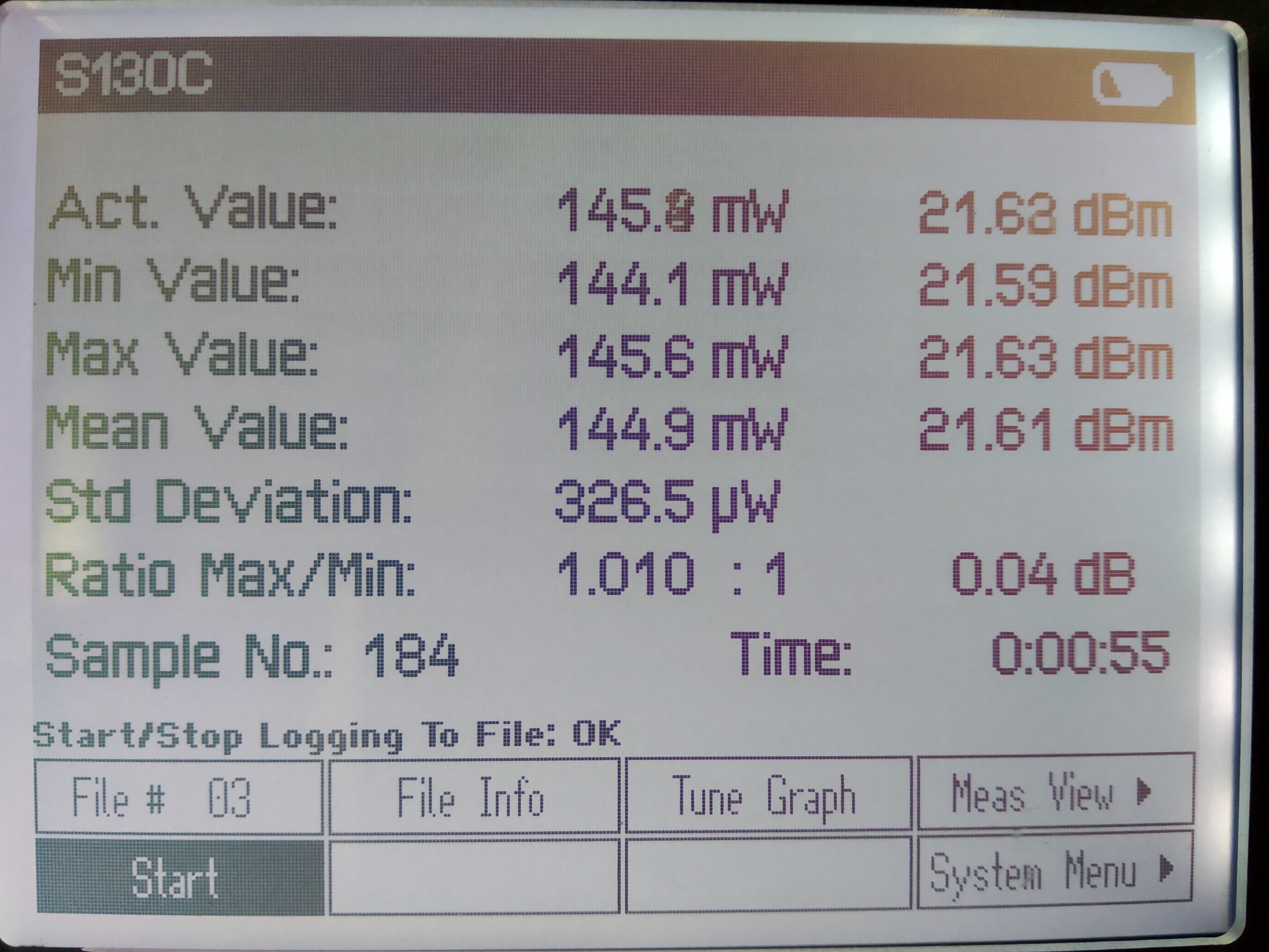
2. BAB beam power now is 145mW.
[Aritomi, Eleonora, Yuhang]
Since we found the problem of unbalance of homodyne, we replaced the wrong coating lens.
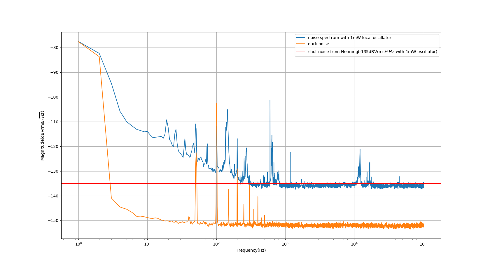
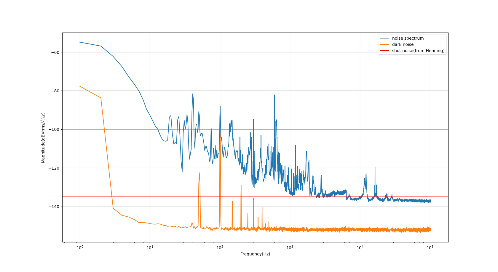
After that we measured the noise spectrum. We can see from this spectrum that
1. The shot noise is limiting above 900Hz. However, there are several peaks still existing in the shot noise region.
2. There is a noise with slope of 1/sqrt(f) below 300Hz. Noise source could be scattering, beam jittering, vibration.
3. We recognize there is 600Hz which comes from molecular pump for vacuum.
[Aritomi, Eleonora]
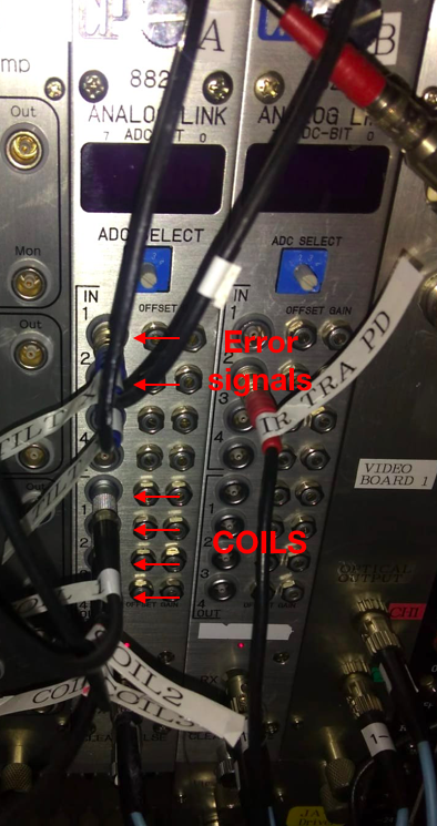
Today we tested the possibility to operate the local controls of the end mirror, by shipping the error and the correction signals with the optical fibers system in place in TAMA.
Details of the optical fiber system are reported in entry #1068. We used the boards "A" (4 input and 4 output channel). See pic 1. We sent two error signals (pitch and yaw) toward the central building and we recived four signals (corresponding to the 4 coils).
In order to perform the test, the signals have been connected to the ADC and DAC of the input mirror. We also used the input mirror CPU and labview VI to test the control. (We temporarily copied the filter and the driving matrix values used for the end mirror)
Conclusion: we could succesfully close the local control loops in this configuration which means that we can go for a stand-alone control system (with all the DAC and ADC in the central area), as planned.
It seems that with the new year, the labview PC is not able to deal with Japanese characters anymore.
Because of this, we had some troubles to run the local control labview project as the path of the files contained some katakana.
The problem was solved by changing the name of the desktop folder from katakana to romaji.
(The origin of the problem is mysterious since nothing has been changed from the last time we used the PC.)
[Aritomi, Yuhang]
First we changed the position of laser illumination point by moving lens in three directions. However, the difference is still the same as before.
Then we measured some values as following.
| Total power | PD1 power(before lens) | PD2 power(before lens) | modulation on PD1 | modulation on PD2 |
| 1.052mW | 489uW | 504uW | 608mV | 752mV |
The ratio of power is reasonable. But the ratio of modulation is not. So we guess the problem should between lens and oscilloscope.
The reason can be: incident angle resulting in different responsivity; lens problem; PD problem
We first tried to change the angle of incident beam on PD1 by doing the 'alignment' of BS and lens. Here alignment means makeing the modulation signal on PD small by BS and recover by lens. However, it doesn't make any difference.
Then we think PD should be fine. And the last check is for lens. However, there is no space to put power meter after the lens. So we take it off from the original position. And put it before the IRMC. The power before and after this lens is
| before | after |
| 1.39mW | 1.09mW |
The ratio of these two power is 0.784. If we make this ratio as 1, the modulation on PD1 should be 775mV. It will be almost the same with PD2. So it explains why we have so large unbalance in homodyne.
This lens is from Nowport lens box(for infrared), however, it seems a green coating.
Conclusion: the unbalance is from using of wrong lens. We have already ordered a proper lens. It should arrive soon.
[Eleonora, Yuhang]
Here I put the spectrum containing all the noise source we have for now. The measurement is done after a reasonable common mode noise rejection. The shot noise level we are using here is -135dBVrms/rtHz and it's from Henning(corresponding to 1mW of incident laser power).
[Yuhang, Eleonora]
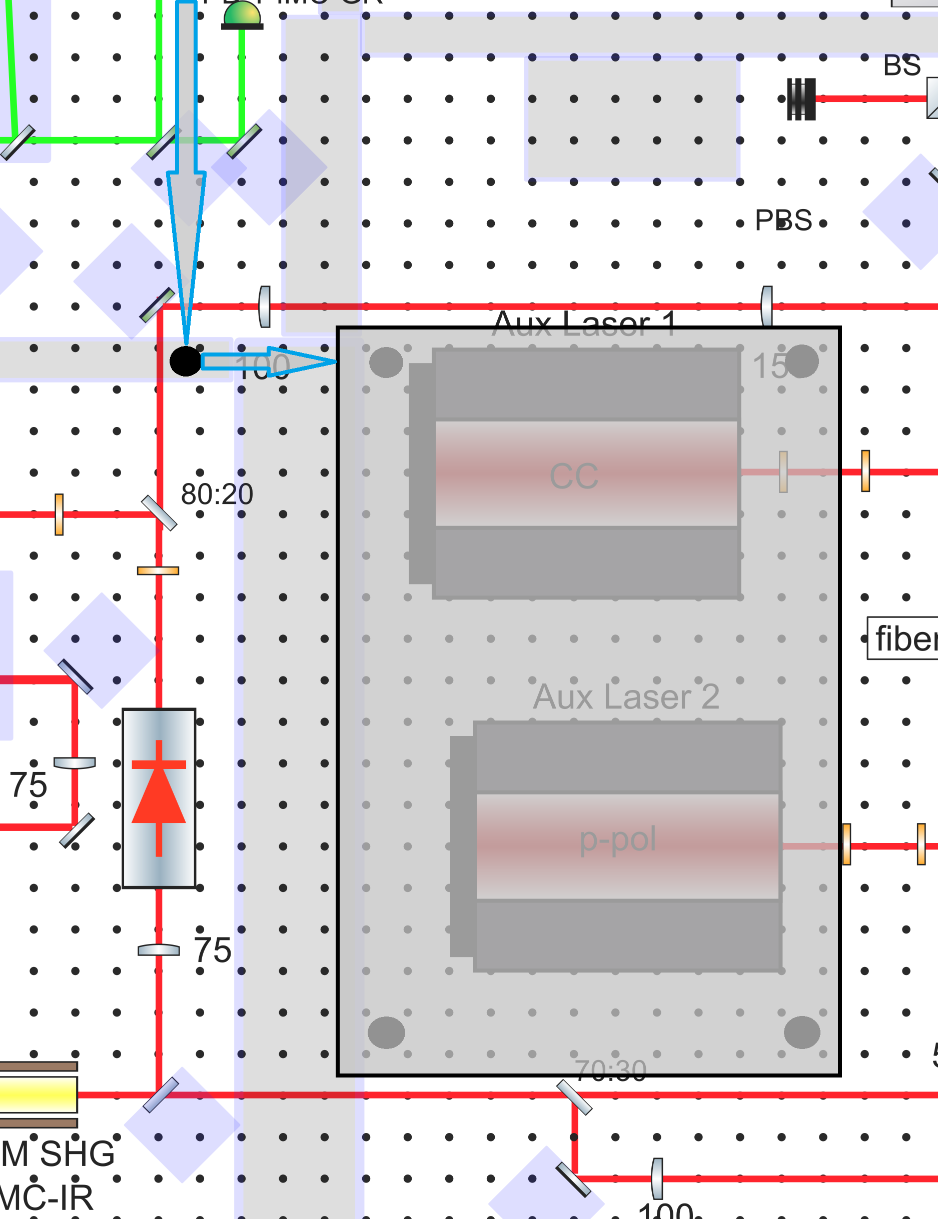
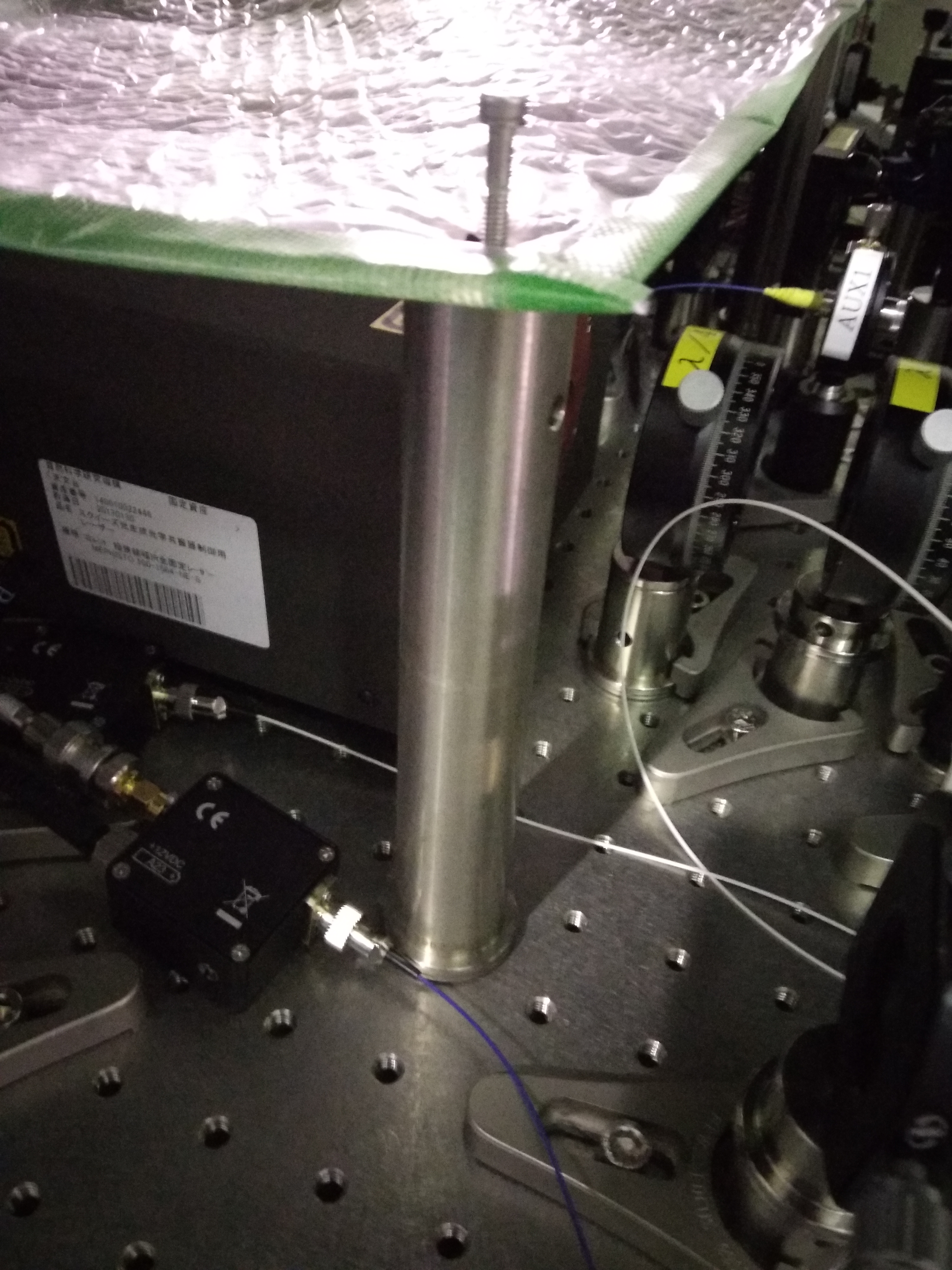
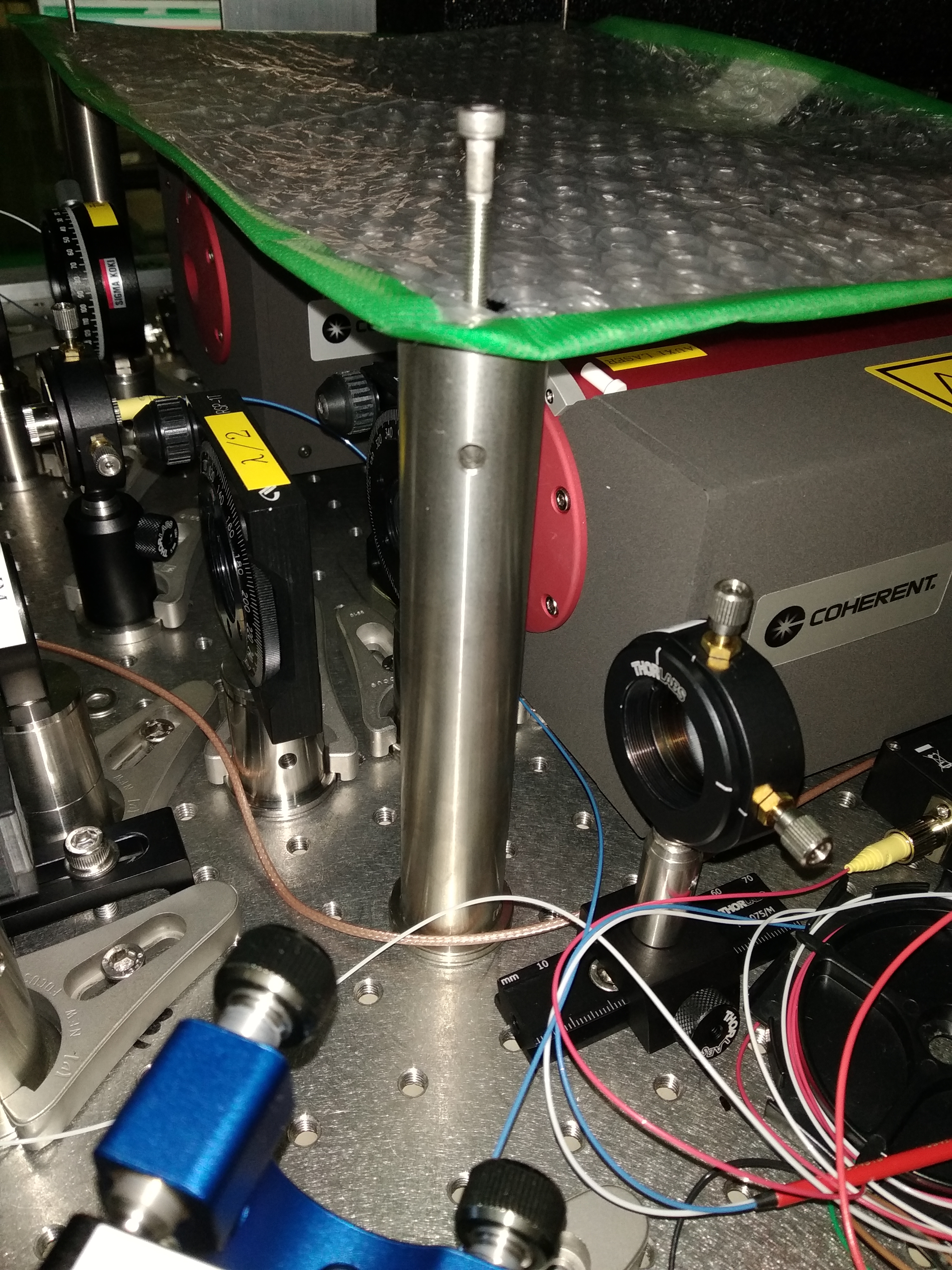
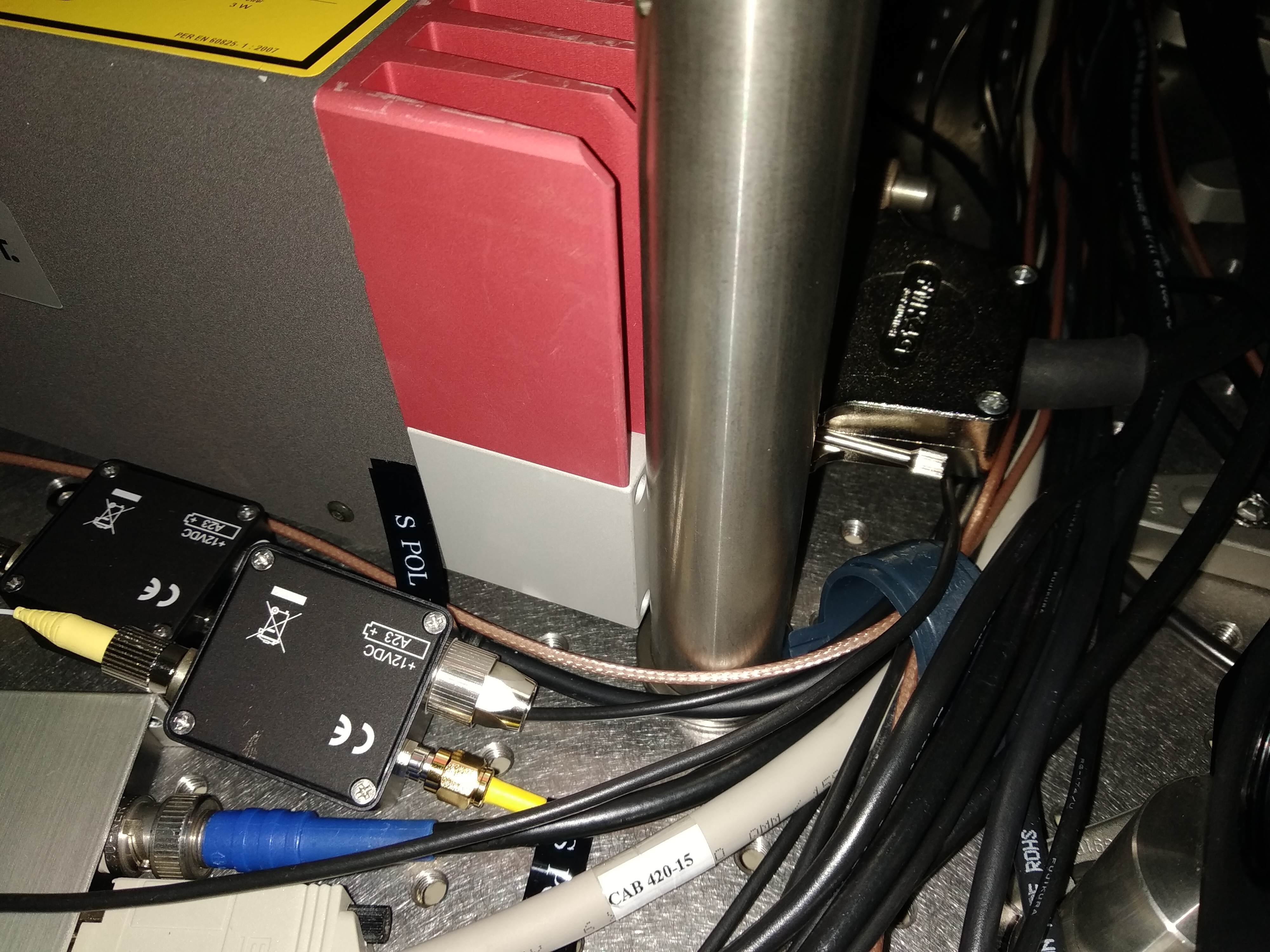
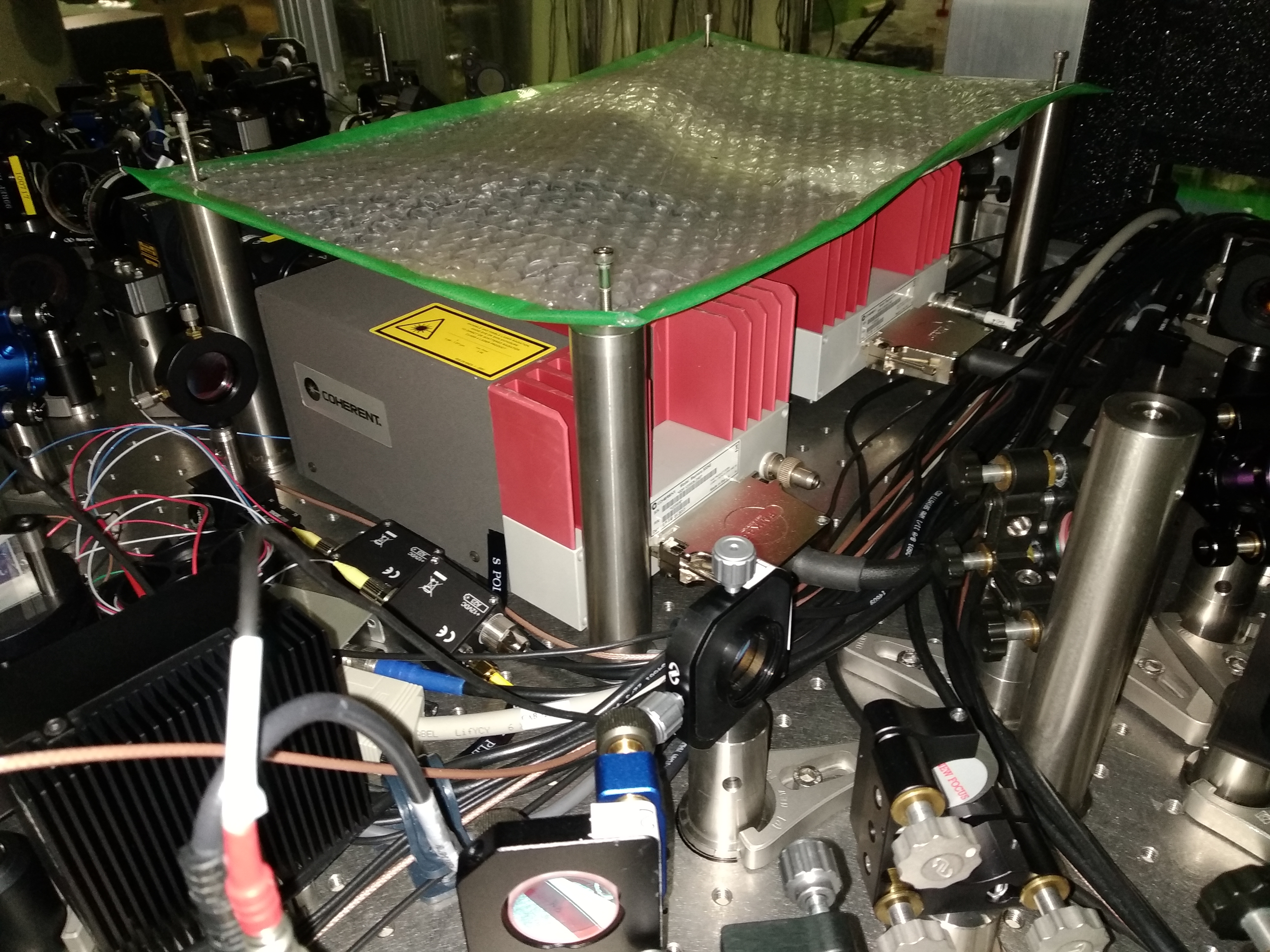
We made a tentative design of the position and dimensions of the breadboard we plan to use for the AA quadrants.
It is shown in the first attached scheme.
The dimension we selected is 300x450 mm (https://www.thorlabs.com/thorproduct.cfm?partnumber=MB3045/M)
According to this design, the reflected beam collected by the Farady isolator is sent to the board by a steering mirror and reach the board after a path of 637mm. (See second attached scheme.) It might be possible to install a lens on this path.
The dimension and position (above the AUX lasers) have been chosen to allow the access to all the optics. If a larger breadbord is needed we can cosider to extend it above the "PLL area".
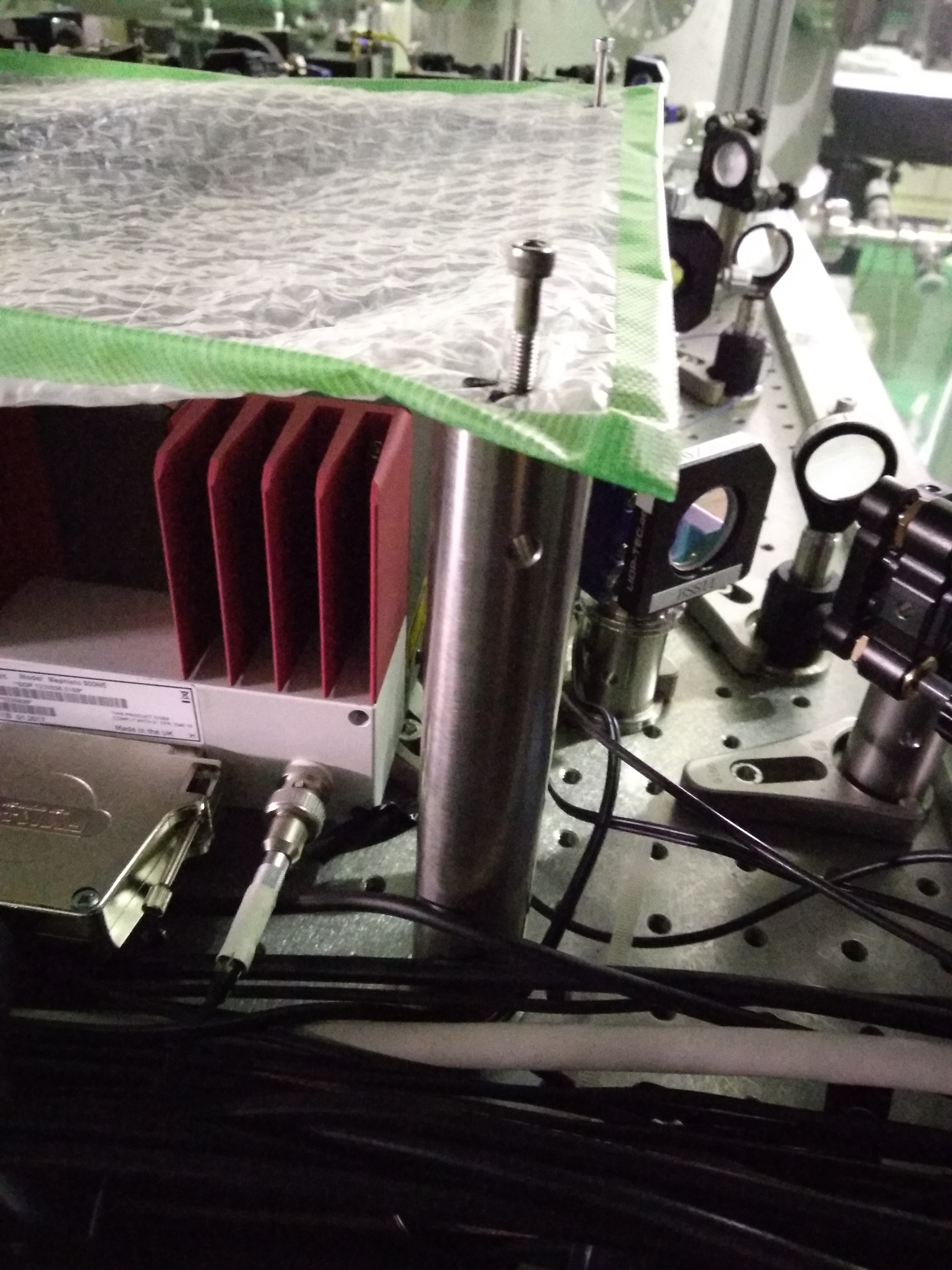
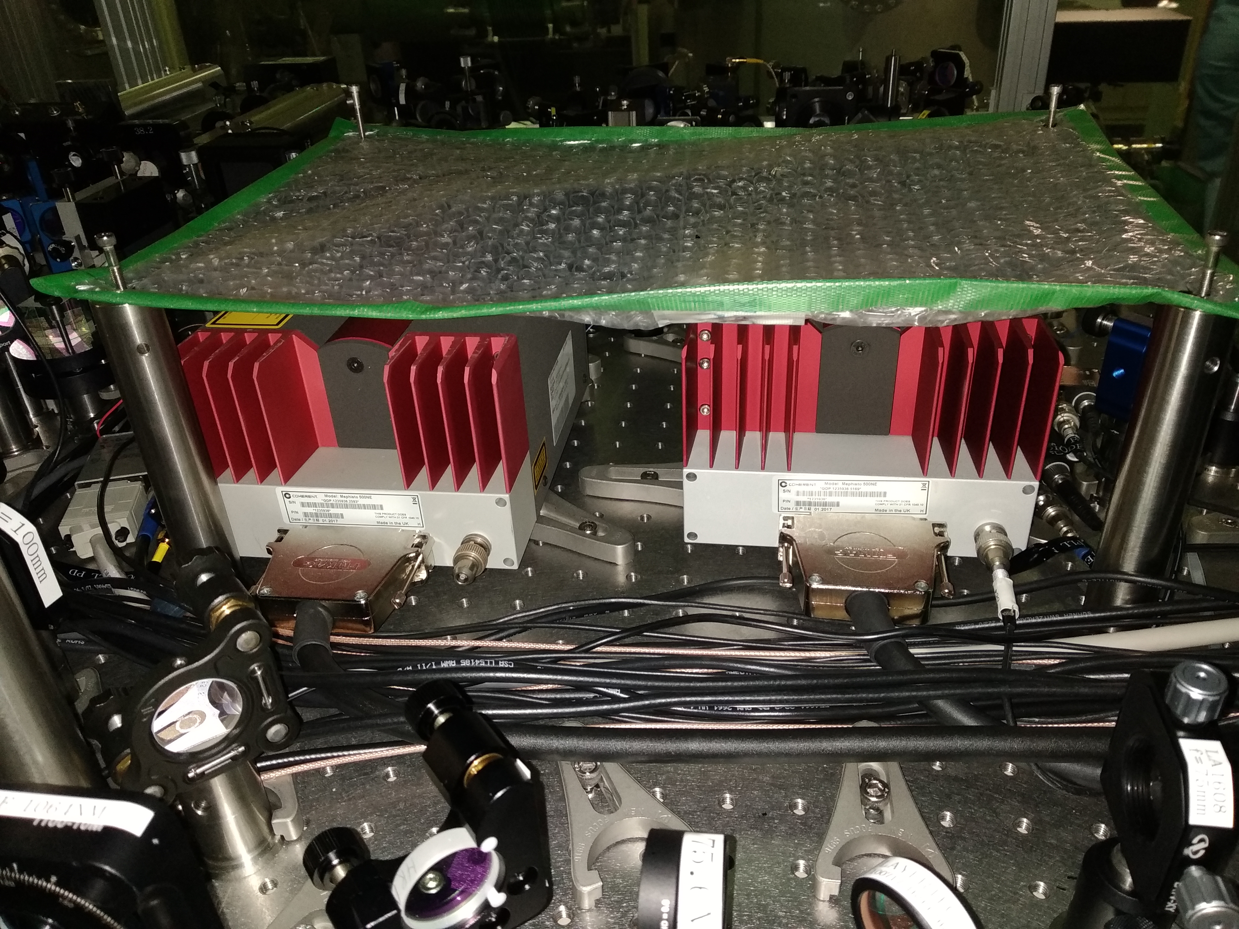
Some pictures of the bench are also attached. Here we used a plastic sheet of the same sized of the board to better visualize the occupied space. Fixing the breadbord posts will require some adjustment of the cables but seems feasable.


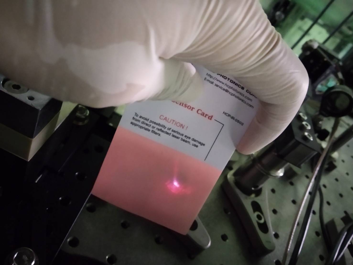
[Aritomi, Yuhang]
This is work on last Friday.
After winter holiday, the second faraday isolator seems to be broken.
Figure 1 shows the transmission of the second faraday isolator.
The beam shape is strange though the beam seems to go through the faraday isolator.
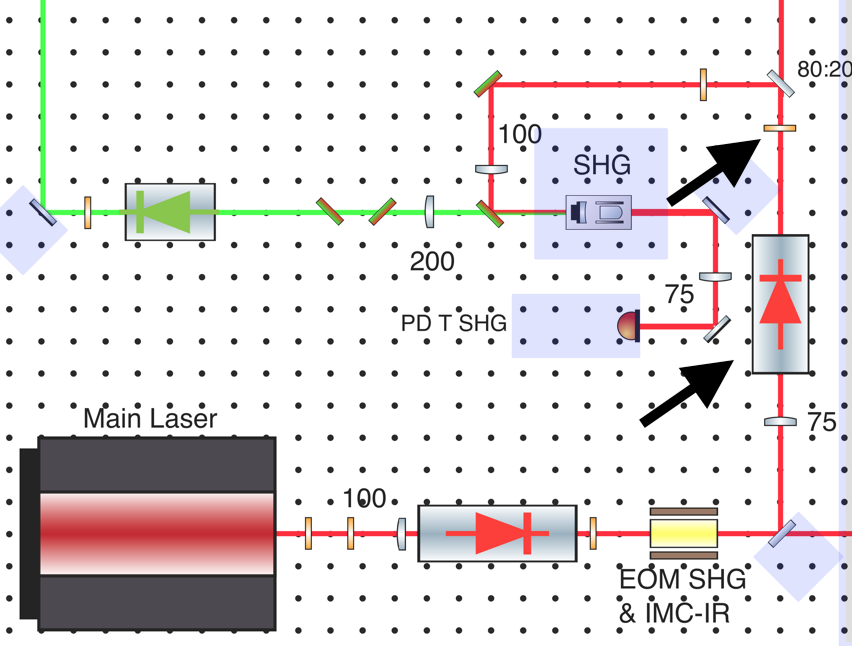
So we removed the isolator and a half wave plate right after it as shown in figure 2.
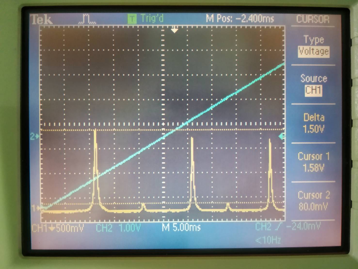
After re-alignment of SHG, mode matching of SHG is 1.5/(1.5+0.08)= 95% as shown in Figure 3.
We plan to buy a new isolator.
[Aritomi, Yuhang]
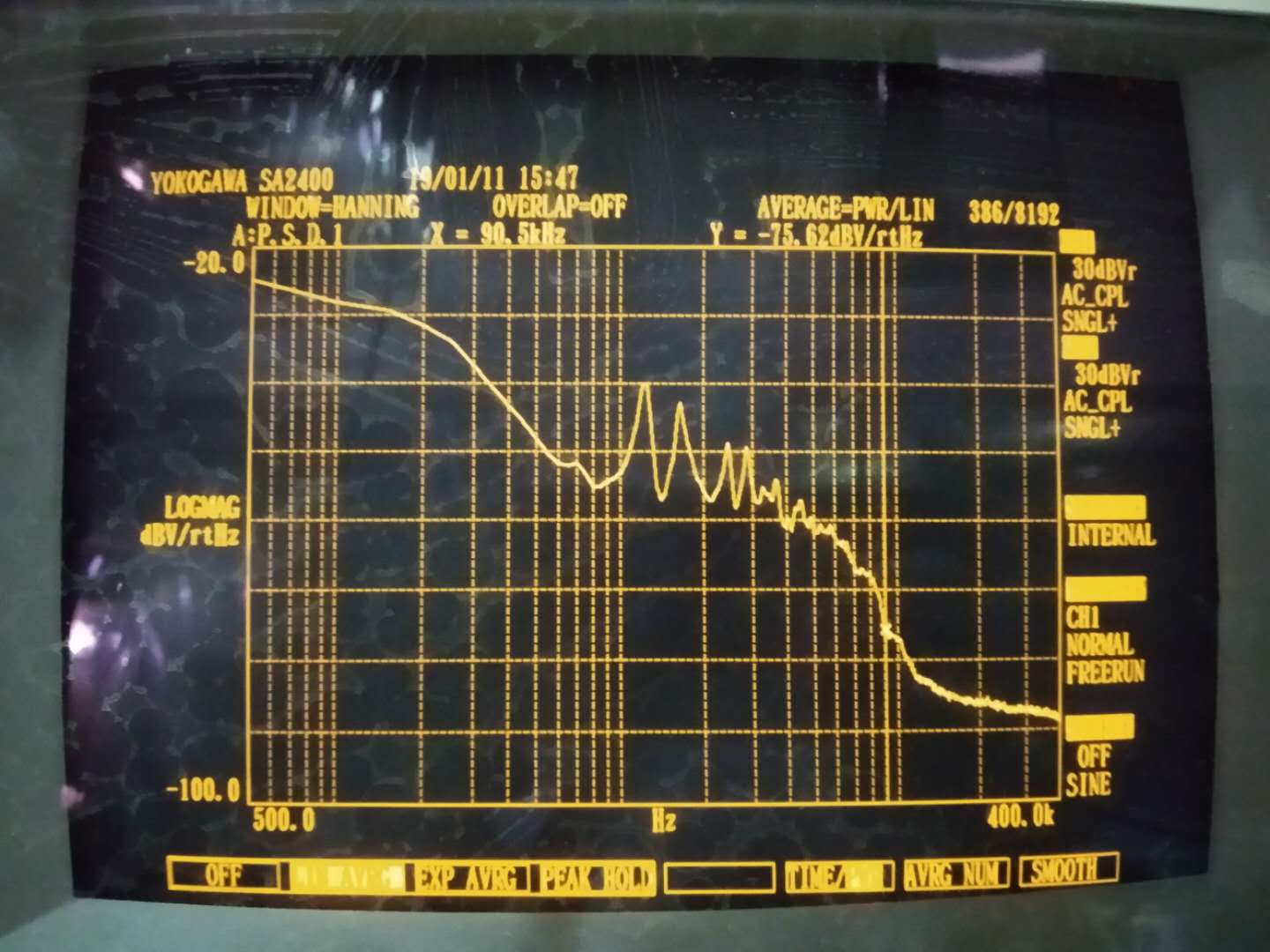
According to Henning result, the shot noise should be -132dBV for 2mW of incident light. In our case, the machine noise is -100dBV. So we use SR560 to amplify it by a factor of 100 means 40dB. So the shot noise level should be -92dBV.
First, we measured the noise spectrum when one of the PD is blocked. The result is shown in the attached figure one. It is clear that not even part of noise spectrum is dominated by shot noise. Even at highest frequency, noise level is around -88dBV.
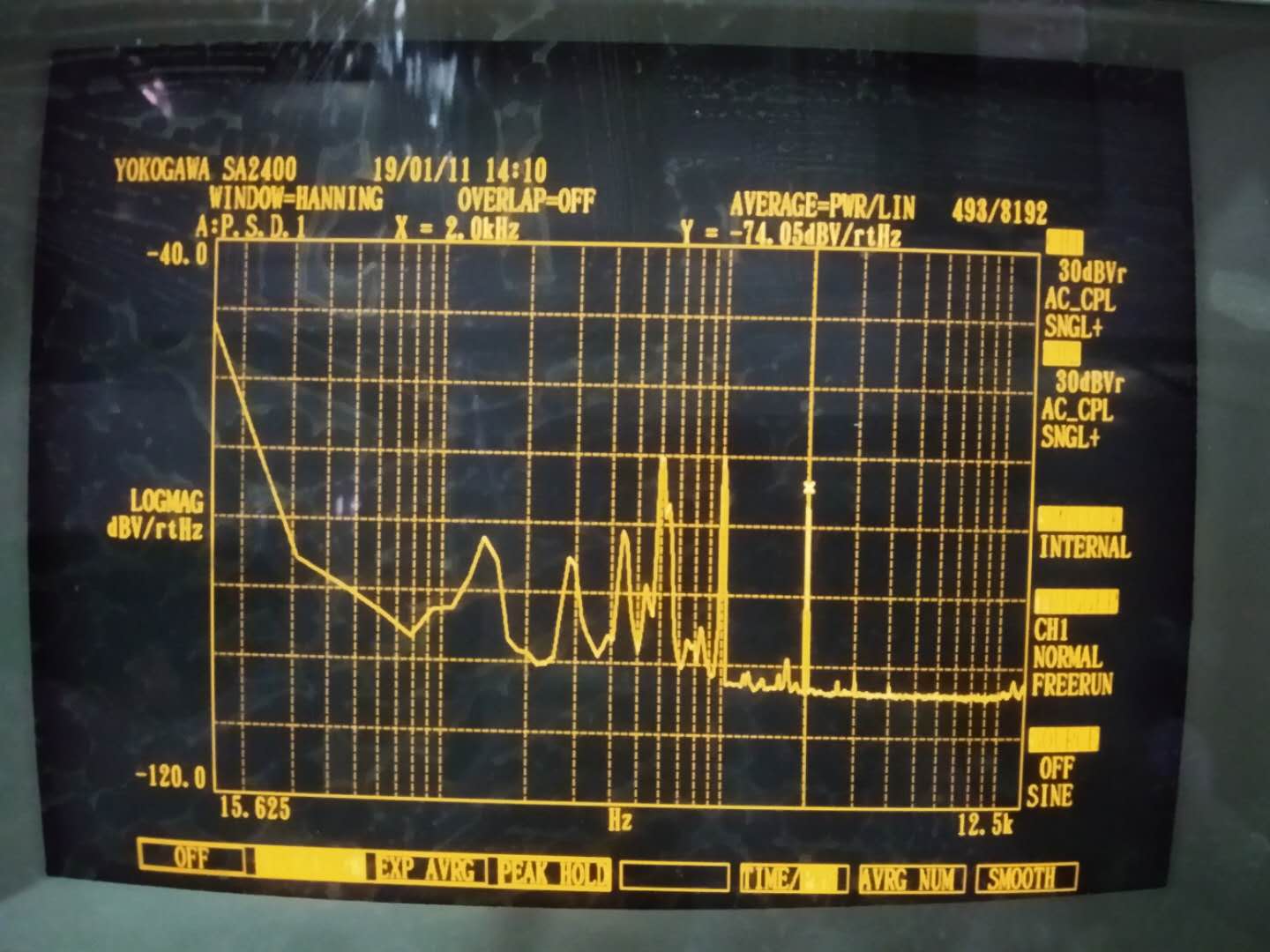
Then we decide to change pitch of steering mirror to change power on the second PD. Maybe this can bring beam away from optimal position. Or the change of beam direction reduce detection efficiency. In the end, we reduced common noise rejection from -30dBV to -74dBV, means we reduce the modulated signal by a factor of 100. The result is shown in the attached figure 2.
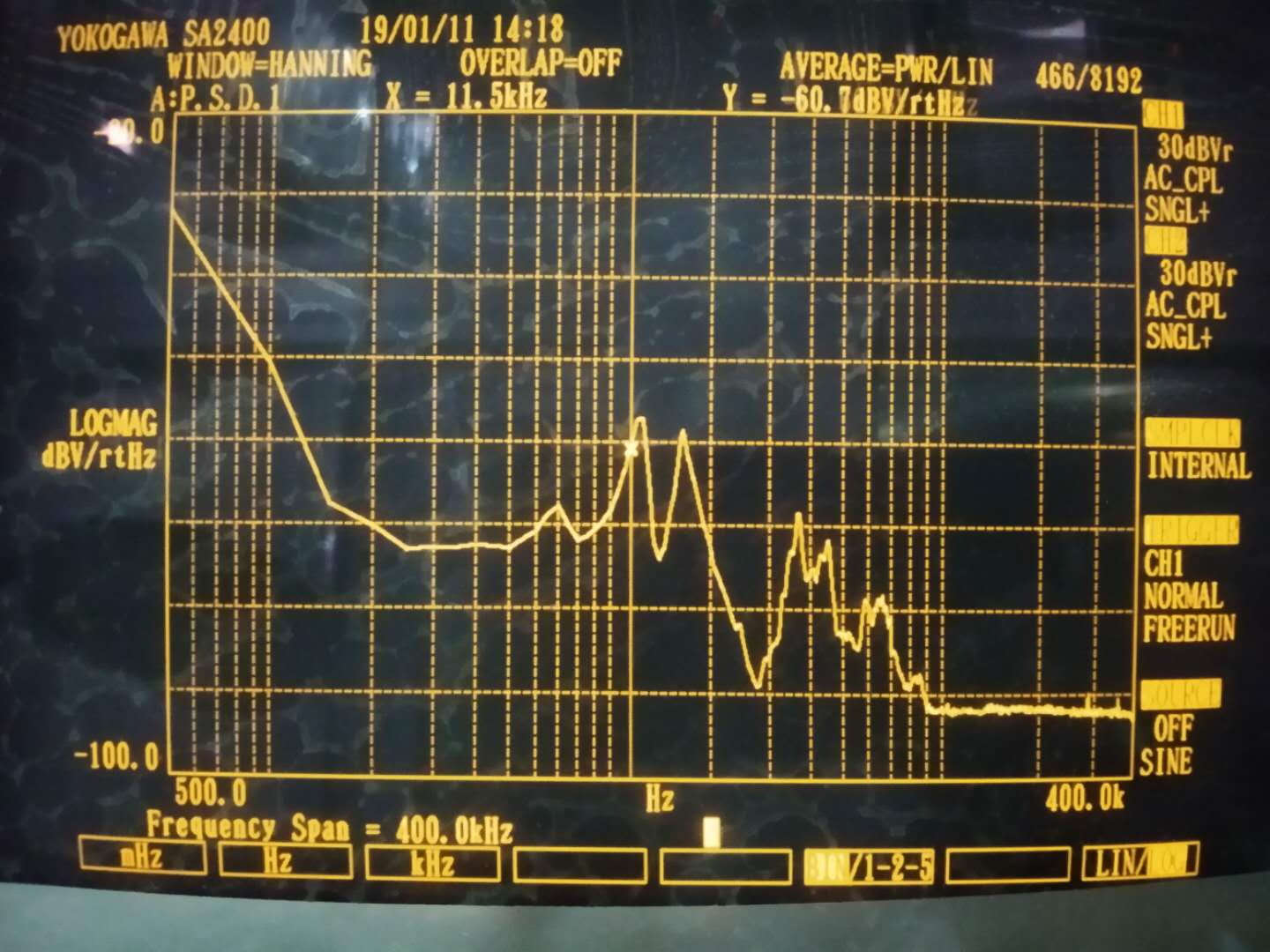
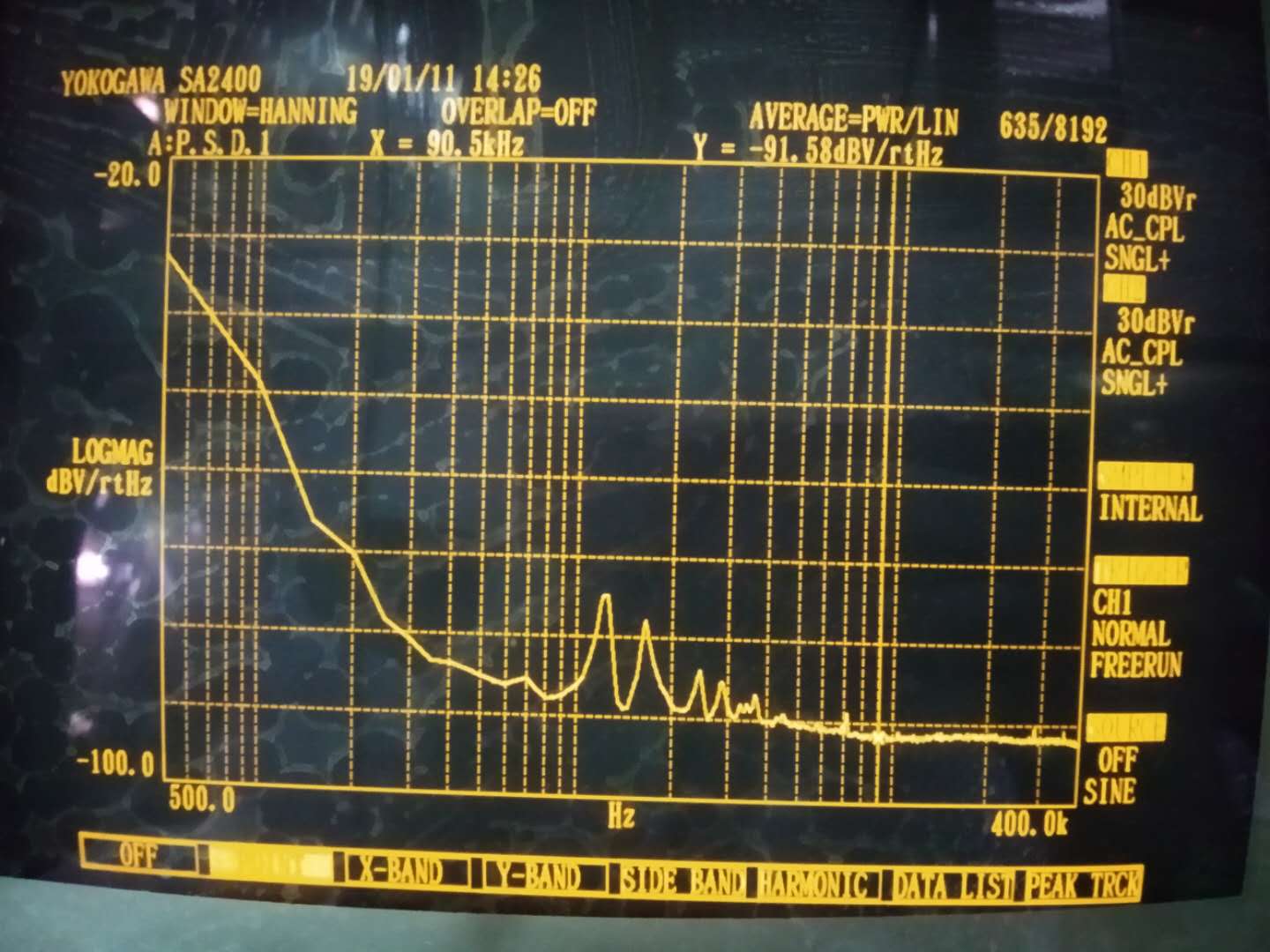
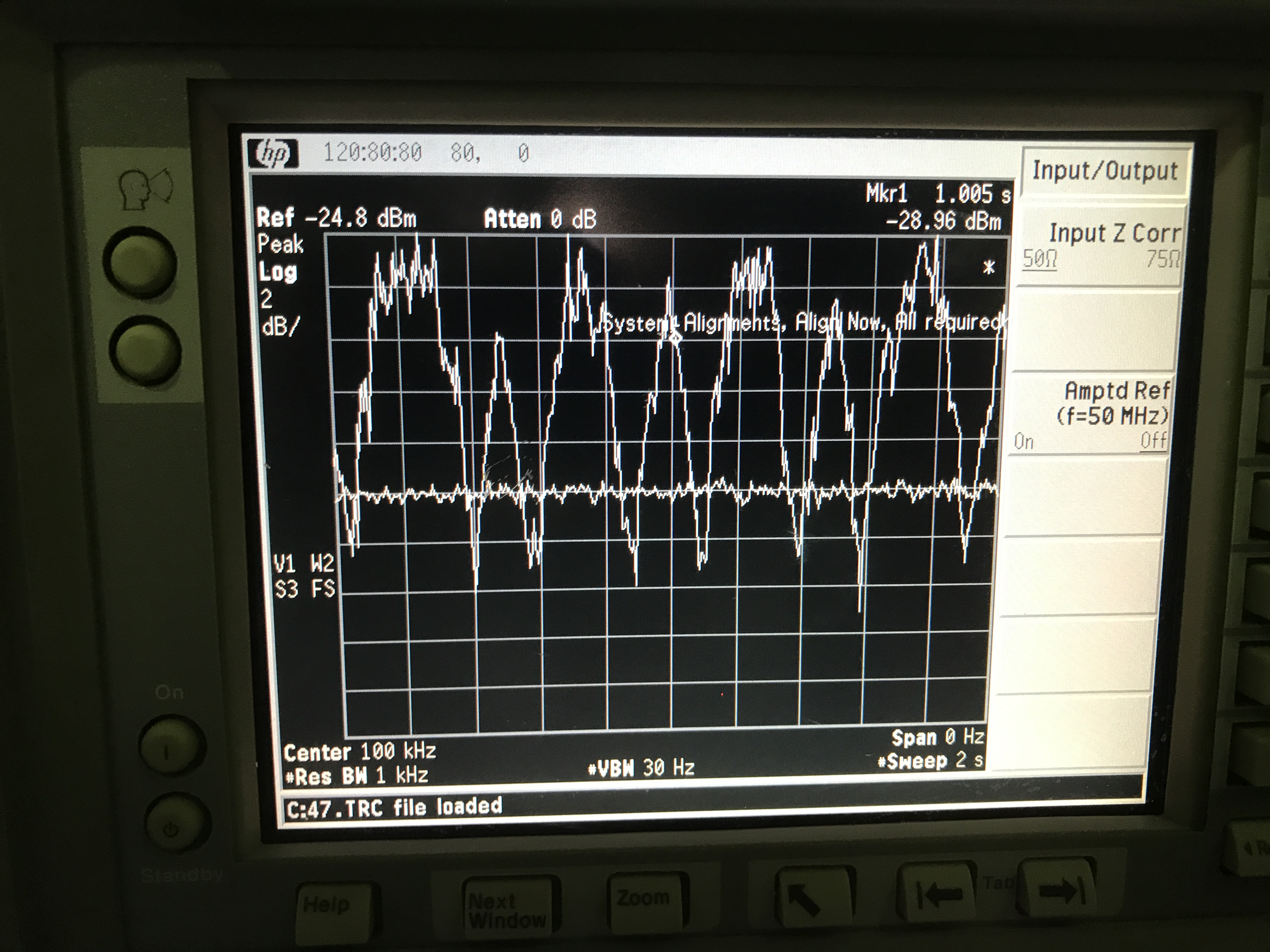
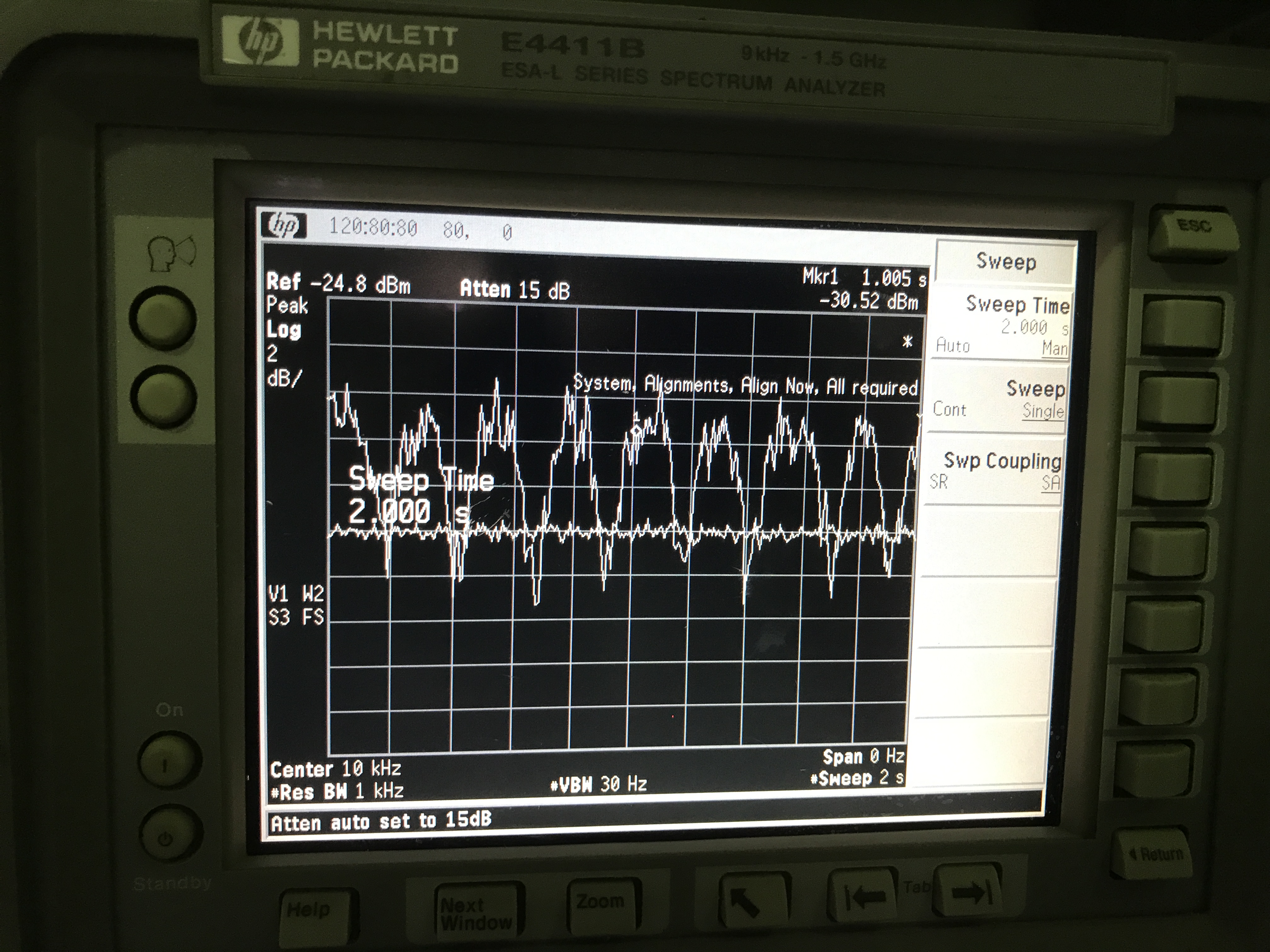
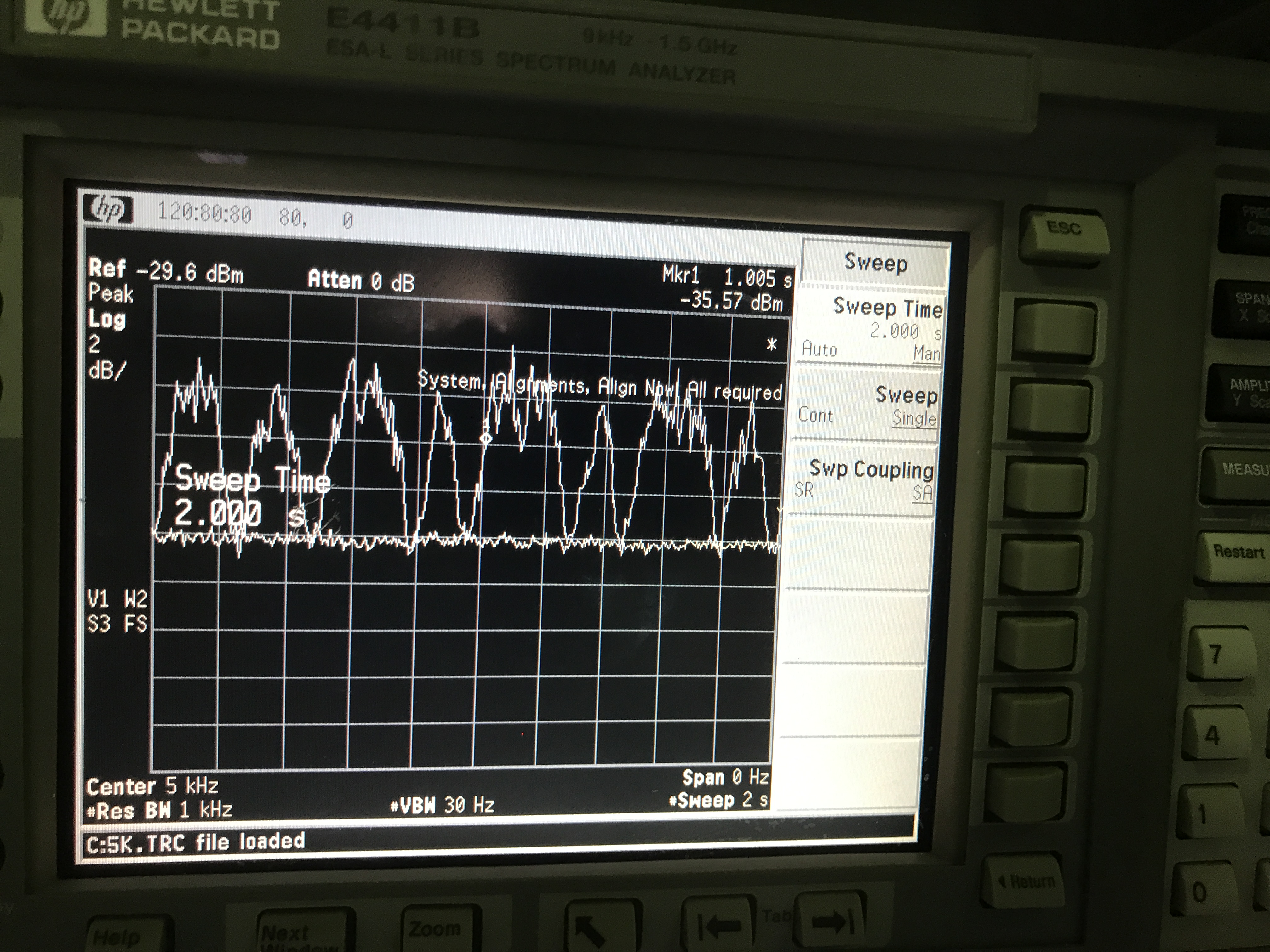
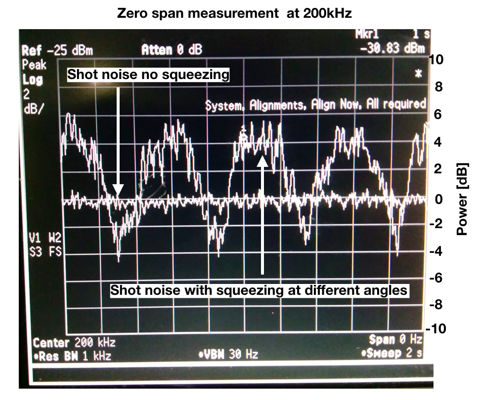
Finally, we turned off modulation. And then we look at the signal from homodyne on spectrum analyzer. The result is shown in the attached figure 3. Then we improve the locking condition of IRMC, make the locking point as close to peak as possible. Then the signal becomes figure 4. This is reasonable because around peak the amplitude change is less. Also seems the noise comes from amplitude noise.
To do list:
1.We can also change the pitch of BS to see if we can increase signal on the first PD.
2. Try to improve locking performance.
3. To see difference when noise eater is engaged and not.
4. Noise hunting