NAOJ GW Elog Logbook 3.2

In preparation for NAOJ blackout, I completely shutdown all filter cavity related electronics.
All cleanroom equipment - lasers, NIM racks, photodetector power supplies, measurement instruments, computer, homodyne PSU, AOM RF amplifier PSU, rack RF amplifier PSU, filter fan. Then I switched off the power at the cluster behind PR/IMC_IN, which is the cleanroom main power.
External equipment - all oplev lasers, PD/QPD, coil drivers and pico controllers (PR, BS, IN, END), SR560, NIM racks, ADC, camera adapters, workstation, monitor, air conditioning main control
More detail later
I tried to find the source of the small squeezing instability, about 1 dB noise floor glitch every second or so. Initially I thought it was from ppol to OPO - I could see weird flashing that was quite frequent. When I was aligning ppol to the OPO I could also see higher order modes appear/disappear at about the glitch frequency. Also, I thought it would be related to ppol because the CC PLL and green controls seemed stable enough, and the homodyne spectrum shows no glitches when only IRMC is locked.
Actually, the ppol transmission spectrum flickering disappears when the SHG is unlocked. I also now notice the same behaviour of the glitchy transmission spectrum when observing OPO transmission of only CC and only main laser. So it's maybe some stray green problem.
I tried to look in squeezing again and somehow the squeezing spectrum didn't show the glitch issue anymore, however, depending on the spectrum analyzer span, there were a lot of noise peaks. So we still have some unclear noise issues.
Then it was time for electrical shutdown so I didn't have time to narrow down the problem further.
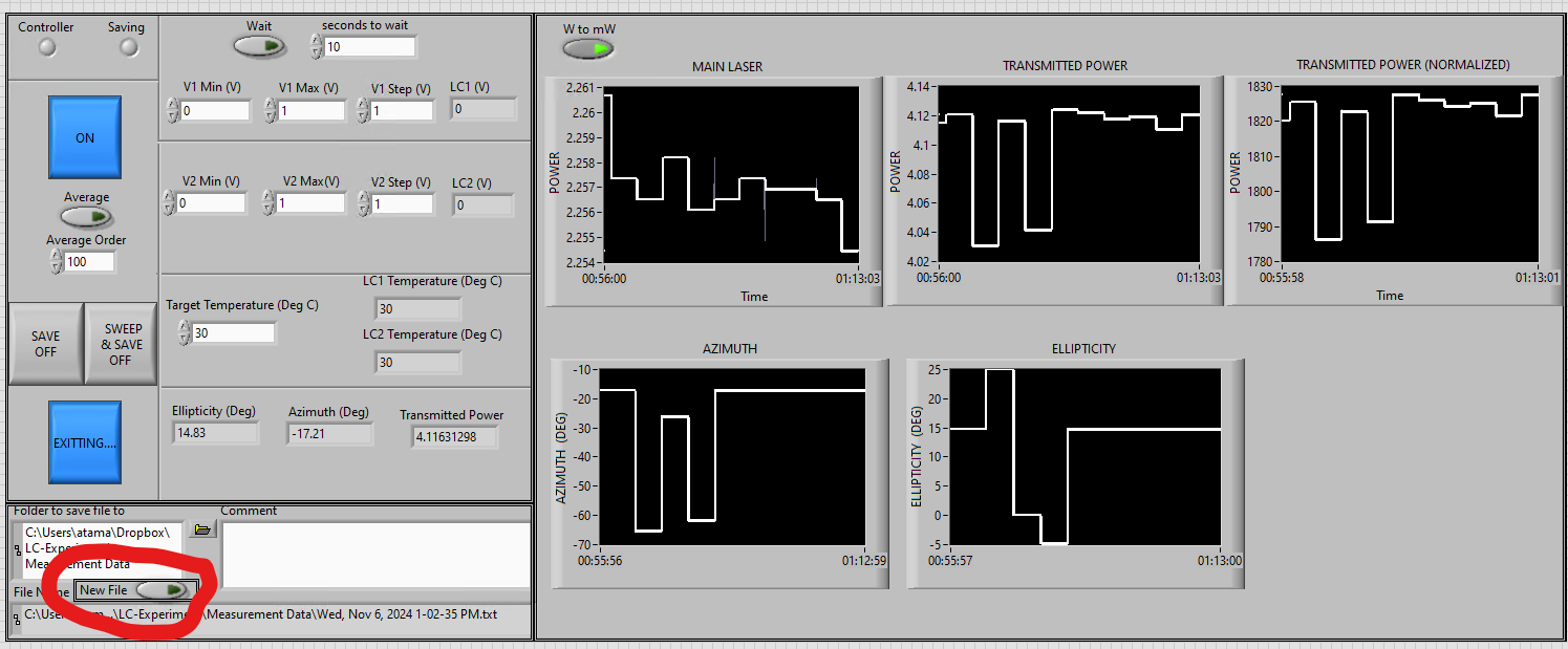
I have added an option to make a newfile inside the vi irrespective of it running..so we don't have to start everytime we want to create a new file. It was very tedious if we wanted to make a new file between measurements as we had to stop the entire VI. This took time as there is a certain warm up time for all instruments after shutting down, espcially camera and LC temperature controller.
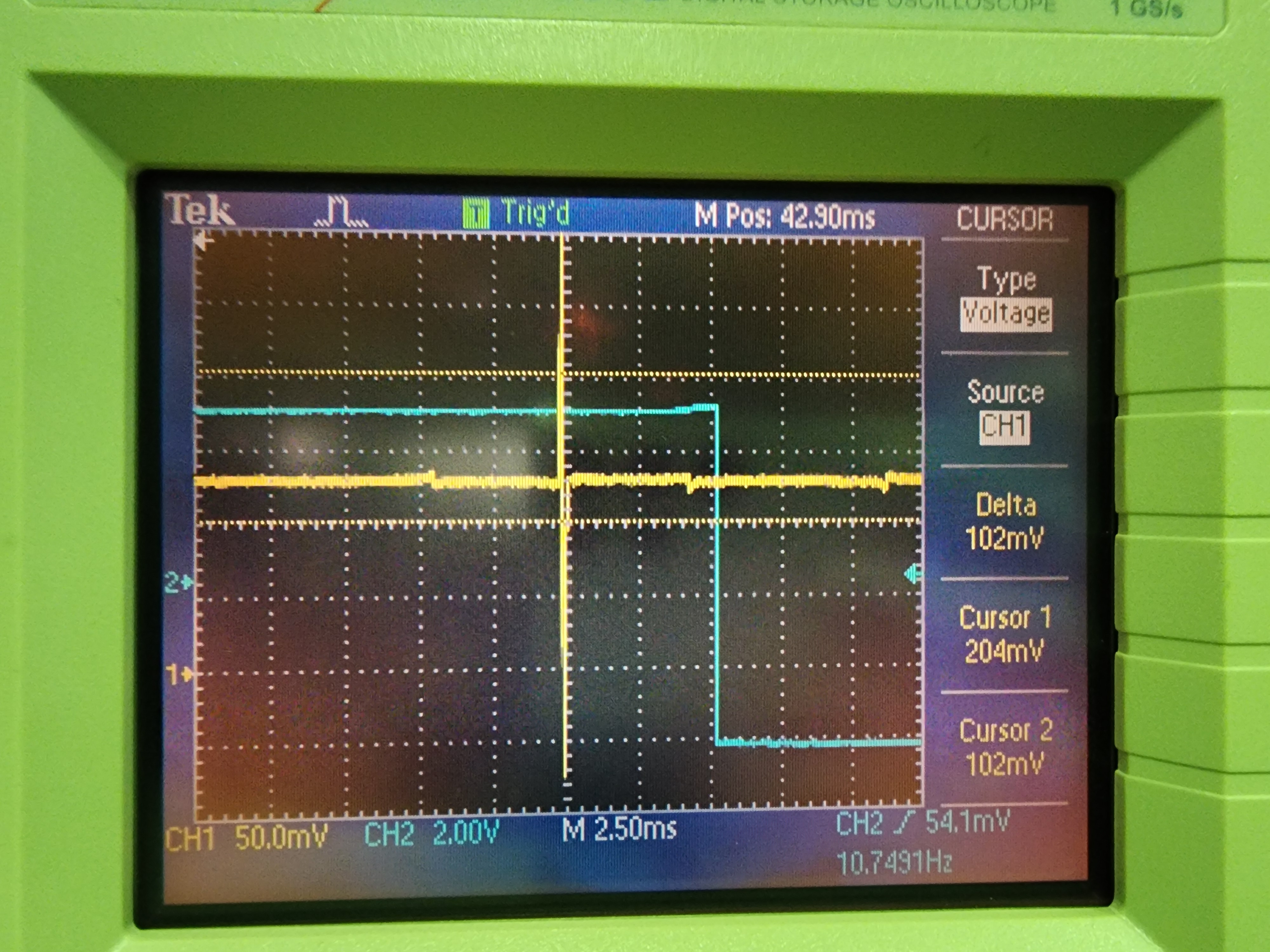
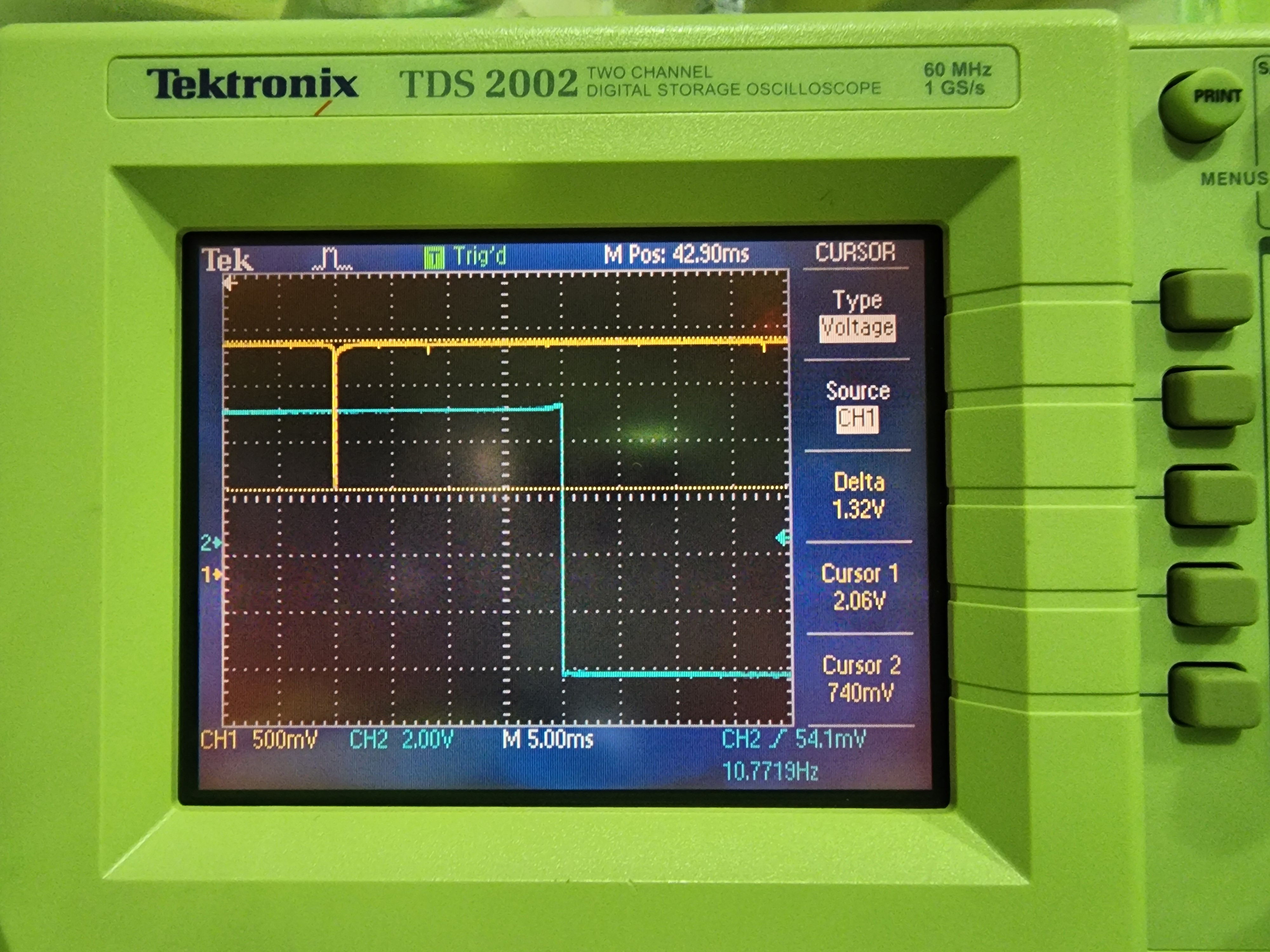
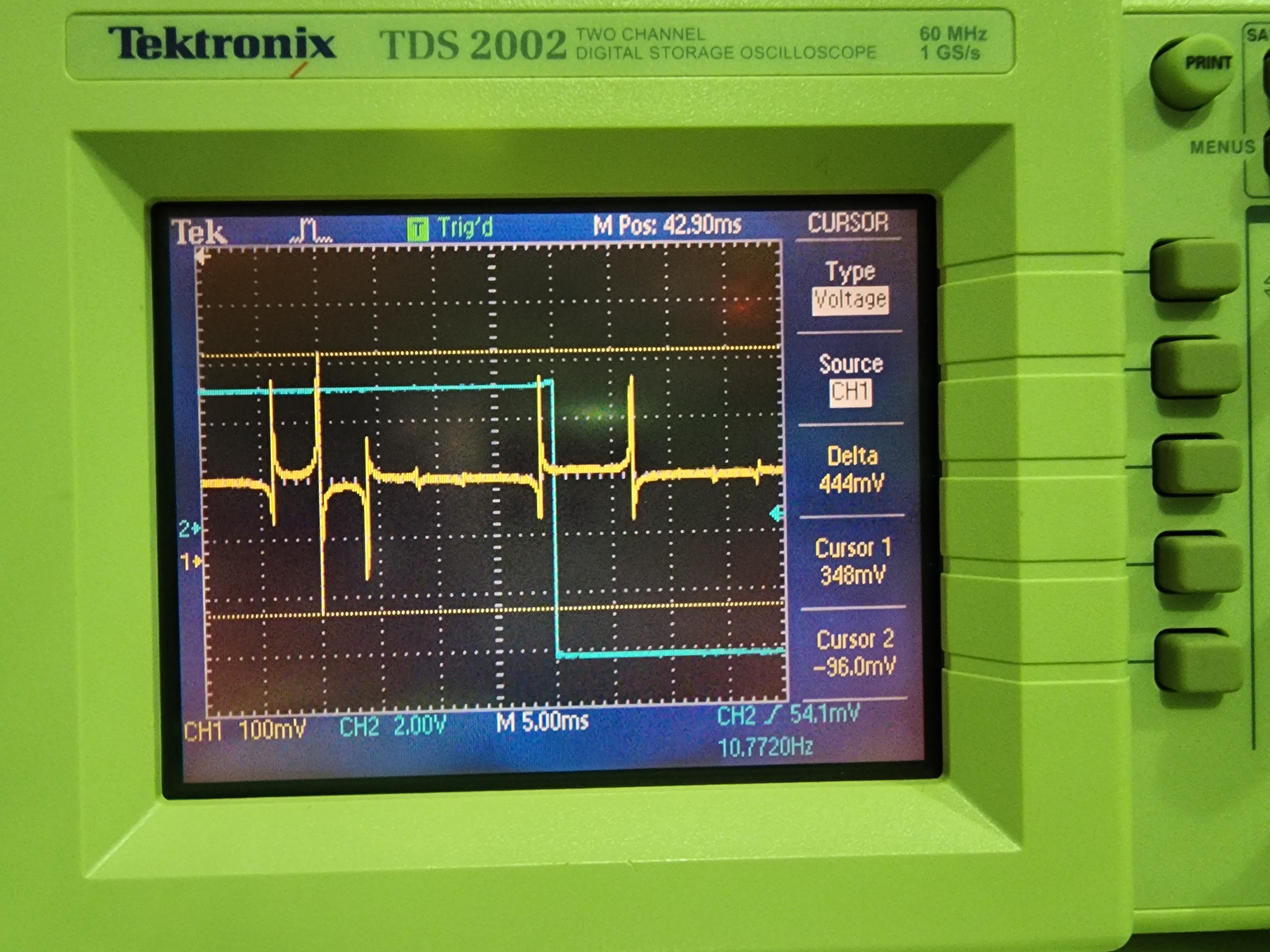
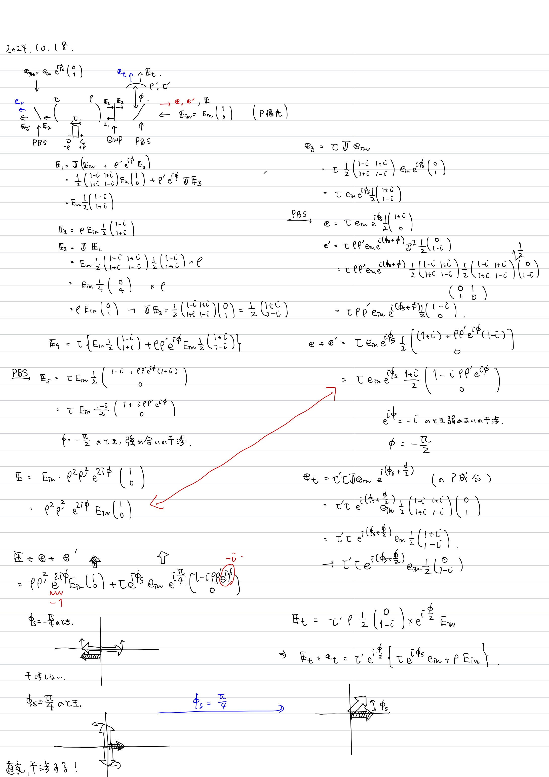
see the part circled in red in the image
I recovered 5-6 dB squeezing and the major nonstationary coherent control/green phase glitch noise is gone!
There is still another lesser glitch source coming from somewhere. It has some relation to the ppol to OPO path, since it is present when all green is blocked and LO shot noise is measured with OPO locked. LO shot noise with OPO unlocked is fine.
BAB nonlinear gain
I optimized the OPO temperature, PLL settings and green alignment to maximize the amplification and deamplification of BAB. Method is to lock OPO using ppol, while transmitting BAB to the stick power meter. Green is unlocked. The phase of green is constantly being modulated sinusoidally so the transmitted BAB level is amplified/deamplified according to the green phase. The optimum OPO temperature is 7.116 kOhm (down from 7.118 kOhm before) and the optimal ppol frequency is 195 MHz (same as before). The green alignment was not too bad, only about 10% off of maximum. This gives a maximum transmitted power measured on the power meter as 1.484 mW, about a factor of 4 increase compared to the transmitted power without green.
LO/sqz overlap
The LO/sqz overlap is optimized by sending both, one at a time, to the alignment mode cleaner (a reference target). LO to AMC mode matching was improved to 99.89% and BAB (sqz) to AMC mode matching was improved to 98.39%. I checked homodyne balance afterwards and it is still zeroed so ok.
CC loop lock
I fixed the stability of the CC PLL loop a while ago, so now it's time to check if the squeezing controls are stable. I locked everything and checked the CC error signals. when turning on the servo scan I can see a modulation that indicates that there is nonlinear gain. Then, I locked. It works! And I could see squeezing. The CC PLL loop remains stable and there is no crazy destabilization of squeezing from before! (characterized by a huge rise in the squeezing noise floor and wacky green phase shifter PZT oscillation to the maximum of 140V).
Squeezing spectrum
There is still some minor glitch noise to be fixed before we can get fast data for Hsien Yi and the Taiwan people. The squeezing spectrum is experiencing a roughly 2 Hz pulse that kind of interrupts the measurement and raises the noise floor by about 1 dB. However, it doesn't raise the noise floor by 10-20 dB so it's nowhere near as bad as before. I can still see the "squeezing level" (about -6 dB). During BAB and ppol alignment I noticed that the infrared transmission through the OPO is experiencing these glitches. Perhaps the ppol PLL could also be fixed a bit. But I'm not entirely sure if it's coming from ppol PLL. It could also be the ppol laser since I noticed weird flashing while aligning it.
I had thought to just go home and brainstorm it later, but I wondered if it was a ppol laser mode hop. I checked and for some reason the ppol laser current and temperature were set to the CC laser values. However, replacing the correct settings didn't fix the new glitch issue.
Misc
GRMZ control loop is quite temperamental. The optimal demodulation phase seems to go between whatever value it wants every now and then. I optimize and then suddenly the PDH signal goes to a bad shape and the optimal demod phase has gone to some other value. The loop sometimes has trouble stabilizing the GR to OPO power level at the proper amount (for reference, GRMC transmission monitor reads 312 mV for 25 mW green injection to OPO) but it seems to get better by switching INV to NON INV or vice versa. It tends to unlock after about 5-10 minutes. Anyway it seems to be a problem primarily with the GRMC error signal but maybe also the MZ loopology.
I left lasers open and both PLLs locked to see if they stay locked over the long weekend.
Nishino,
2024.10.31
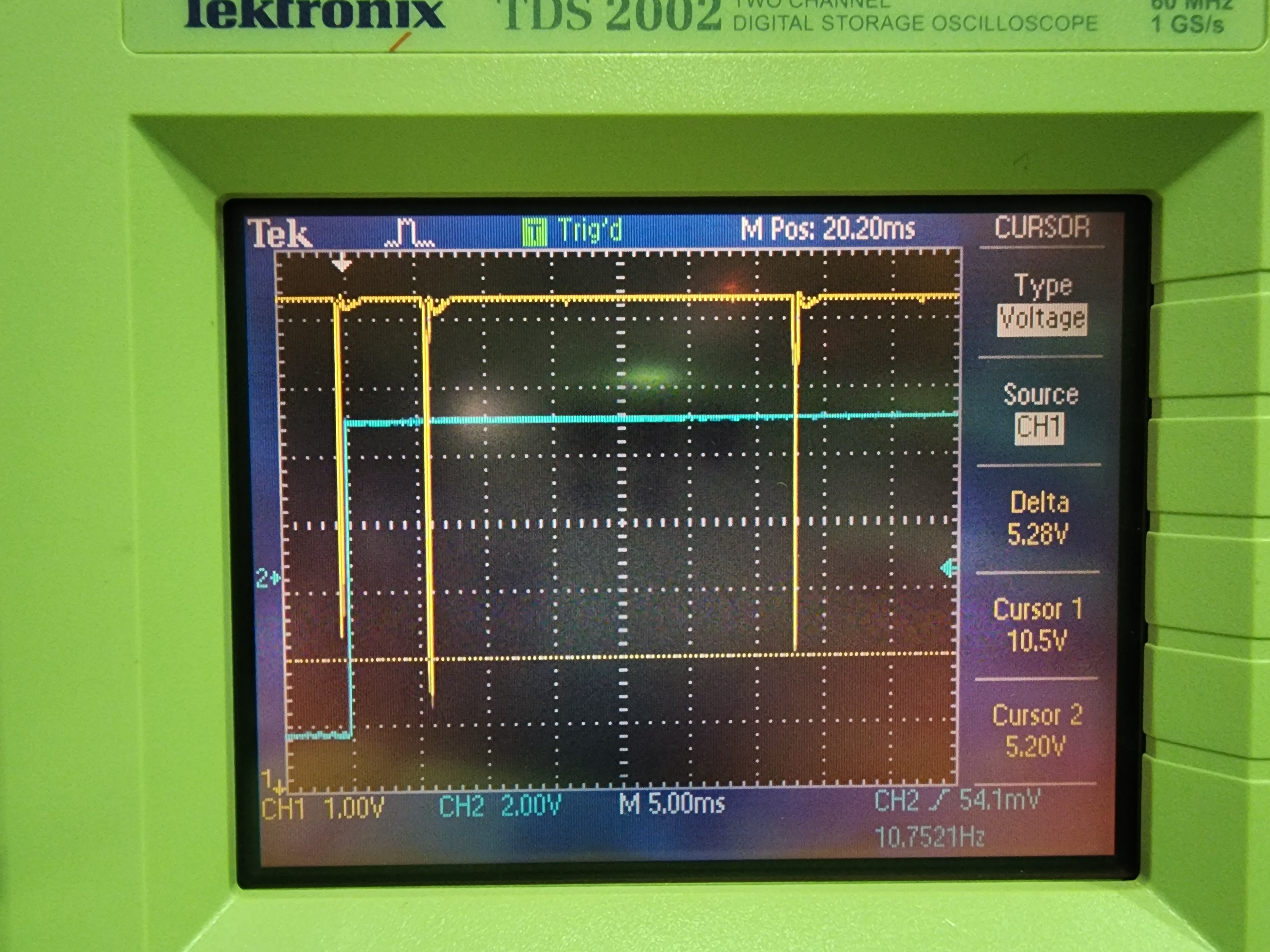
I characterized the GR locking loop. UGF is 580 Hz with the phase margin of ~40 degrees.
Figures:
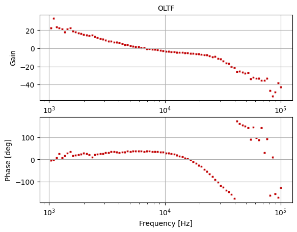
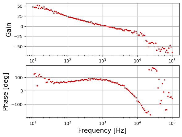
1) Open loop transfer function (G)
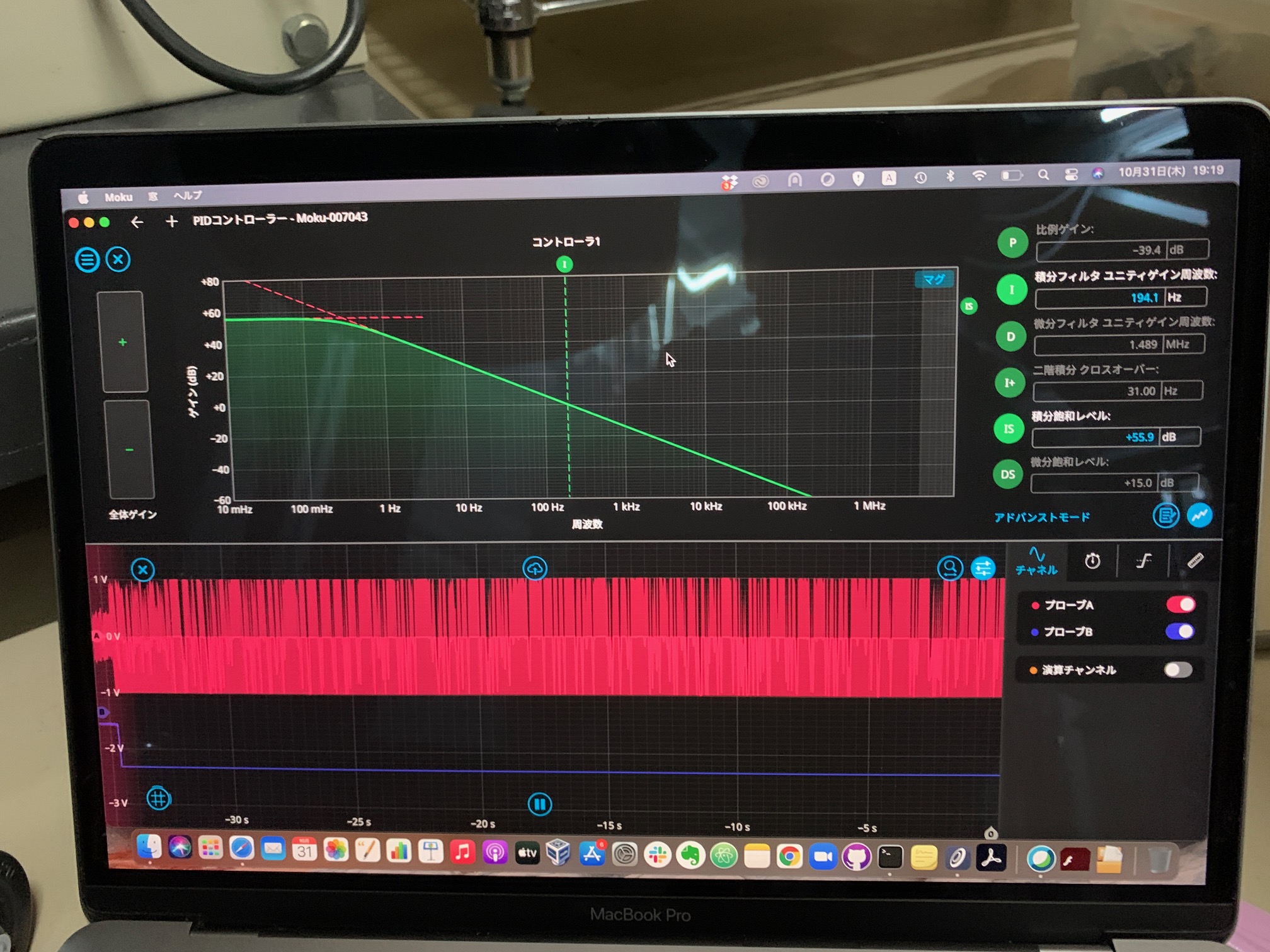
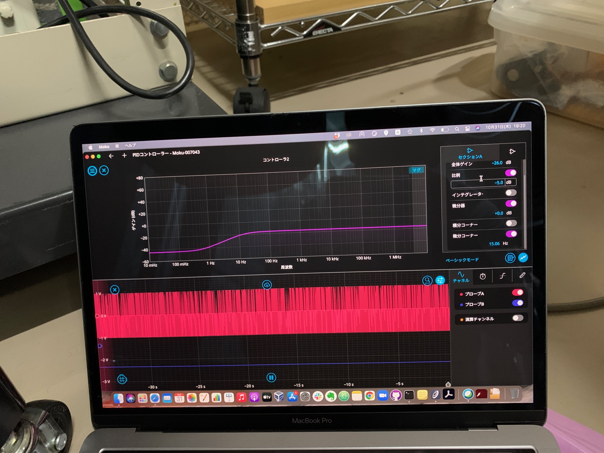
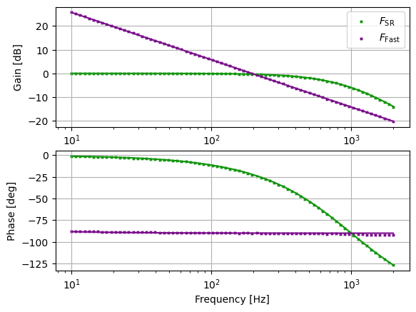
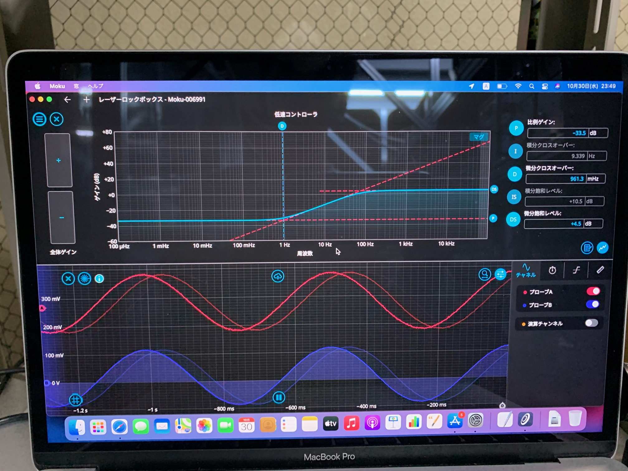
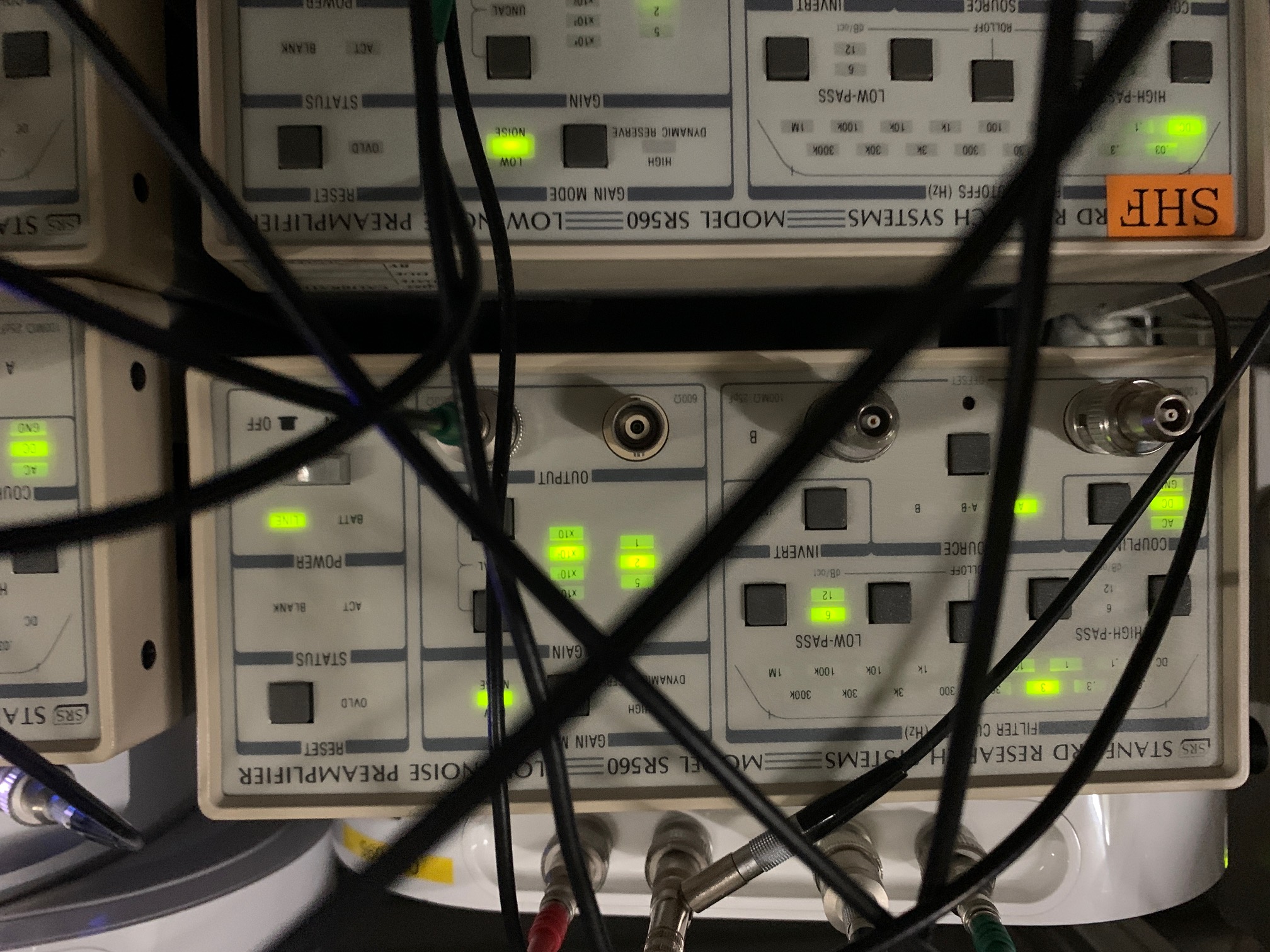
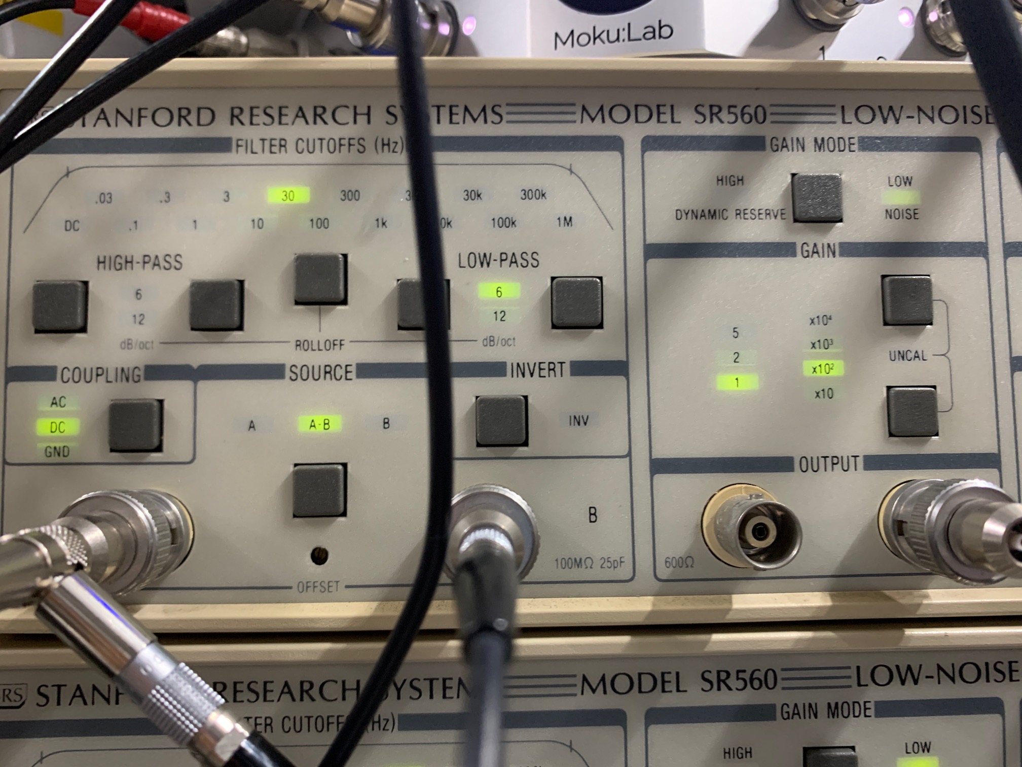
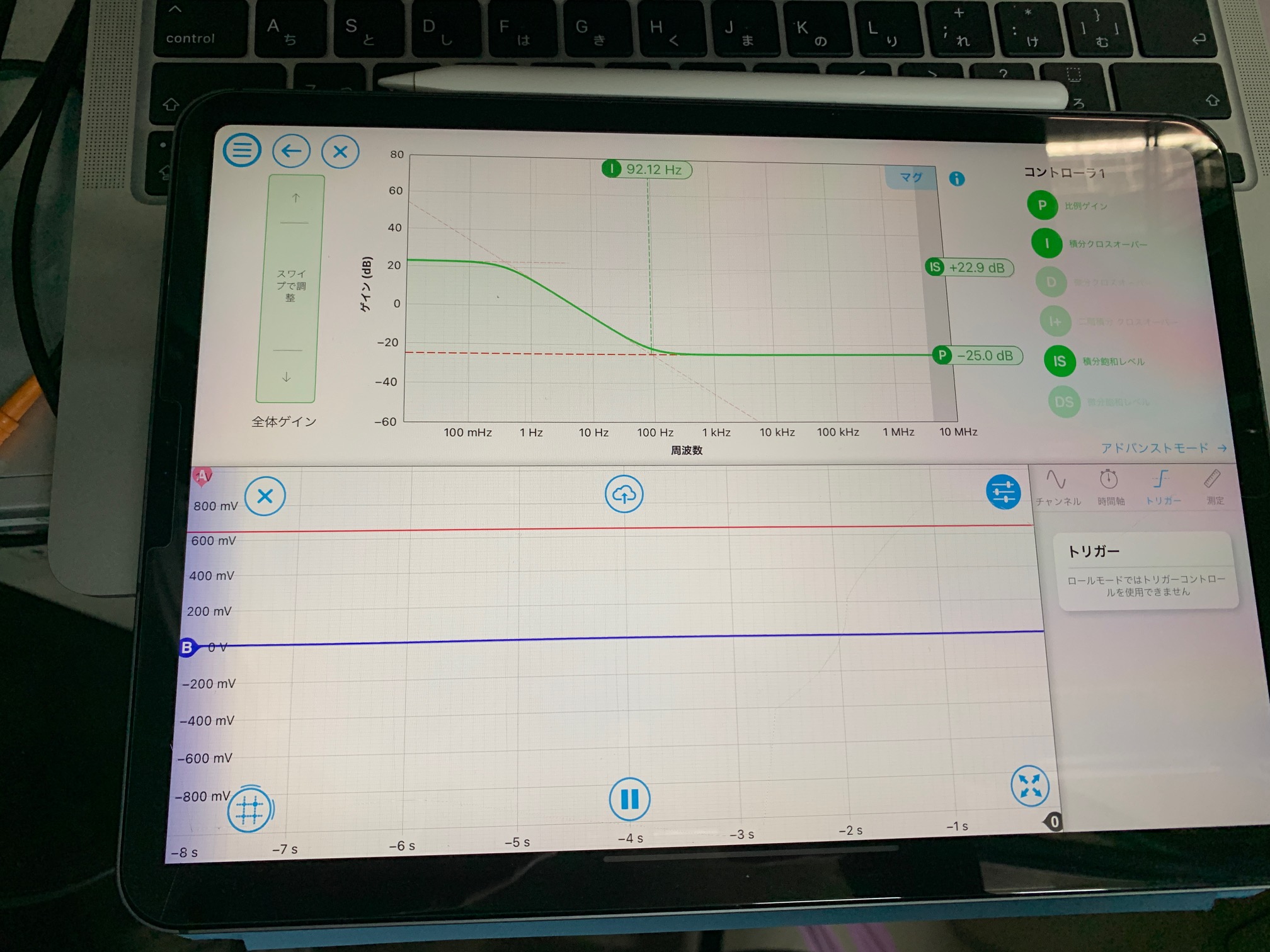
6) Filters of SR560 and Moku PID controller (F)
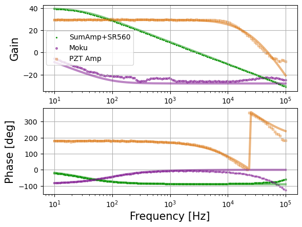
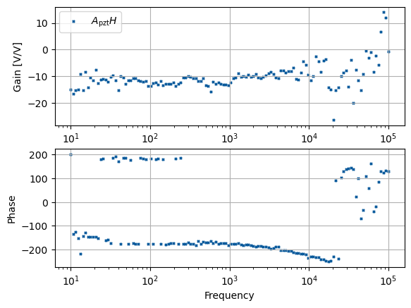
2) G/F=AH, A: PZT actuator efficiency, H: optical gain
3-5) Settings of SR560, Moku fast, and, slow controller
Nishino,
2024.10.31 (see mainOLTF_retake/OLTF_retake.ipynb)
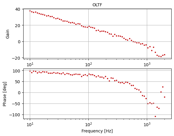
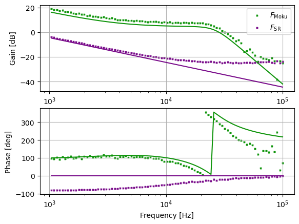
I characterized the GR locking loop. UGF is 7.0 kHz with the phase margin of ~30 degrees.
Figures:
1) Open loop transfer function (G)
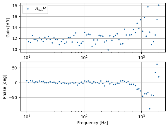
2) Filters of SR560 and Moku PID controller (F)
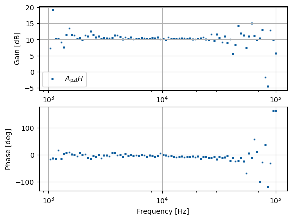
3) G/F=AH, A: PZT actuator efficiency, H: optical gain
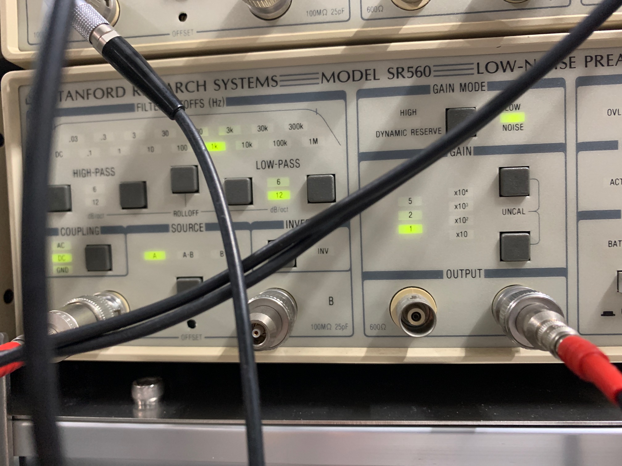
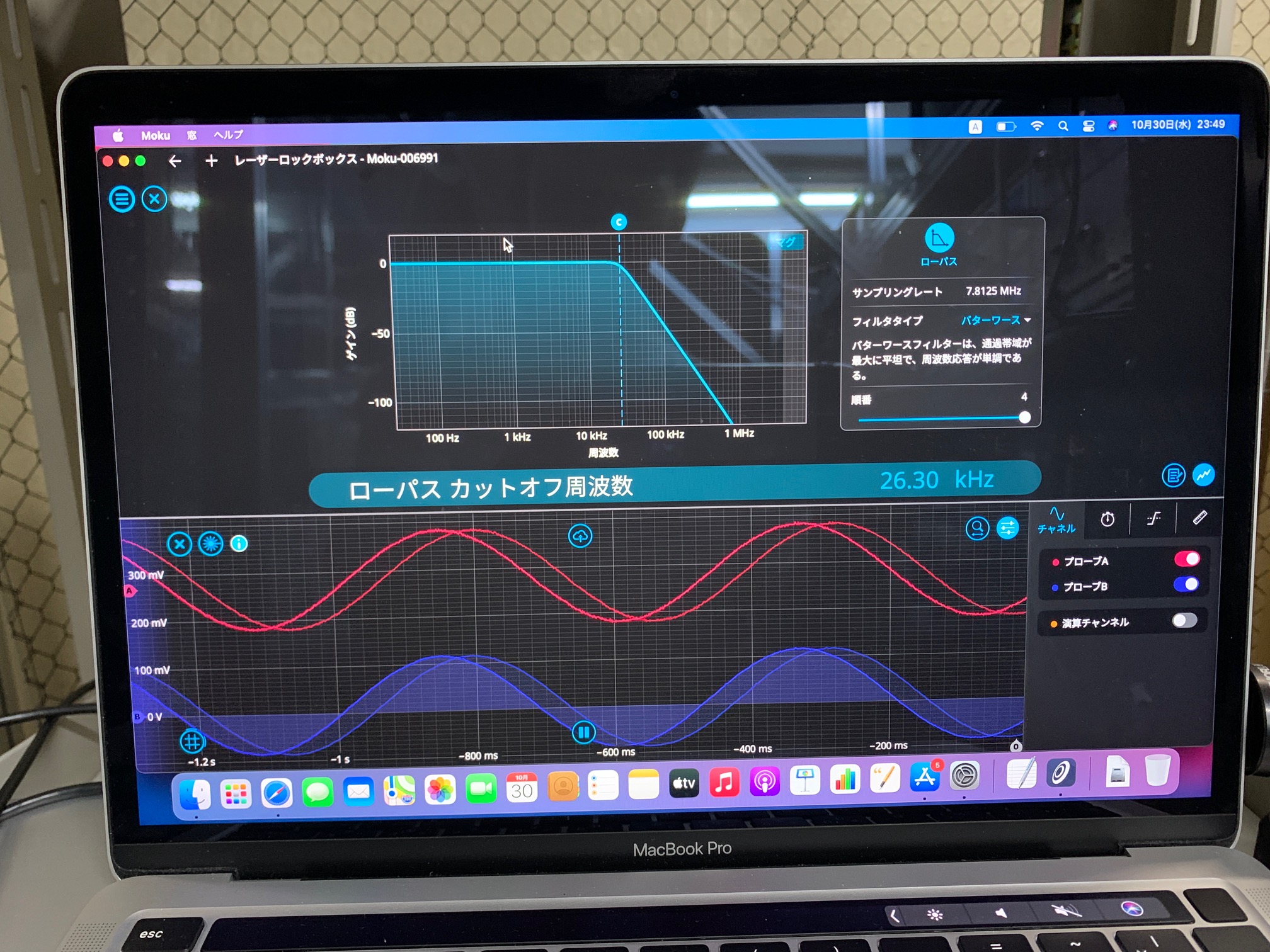
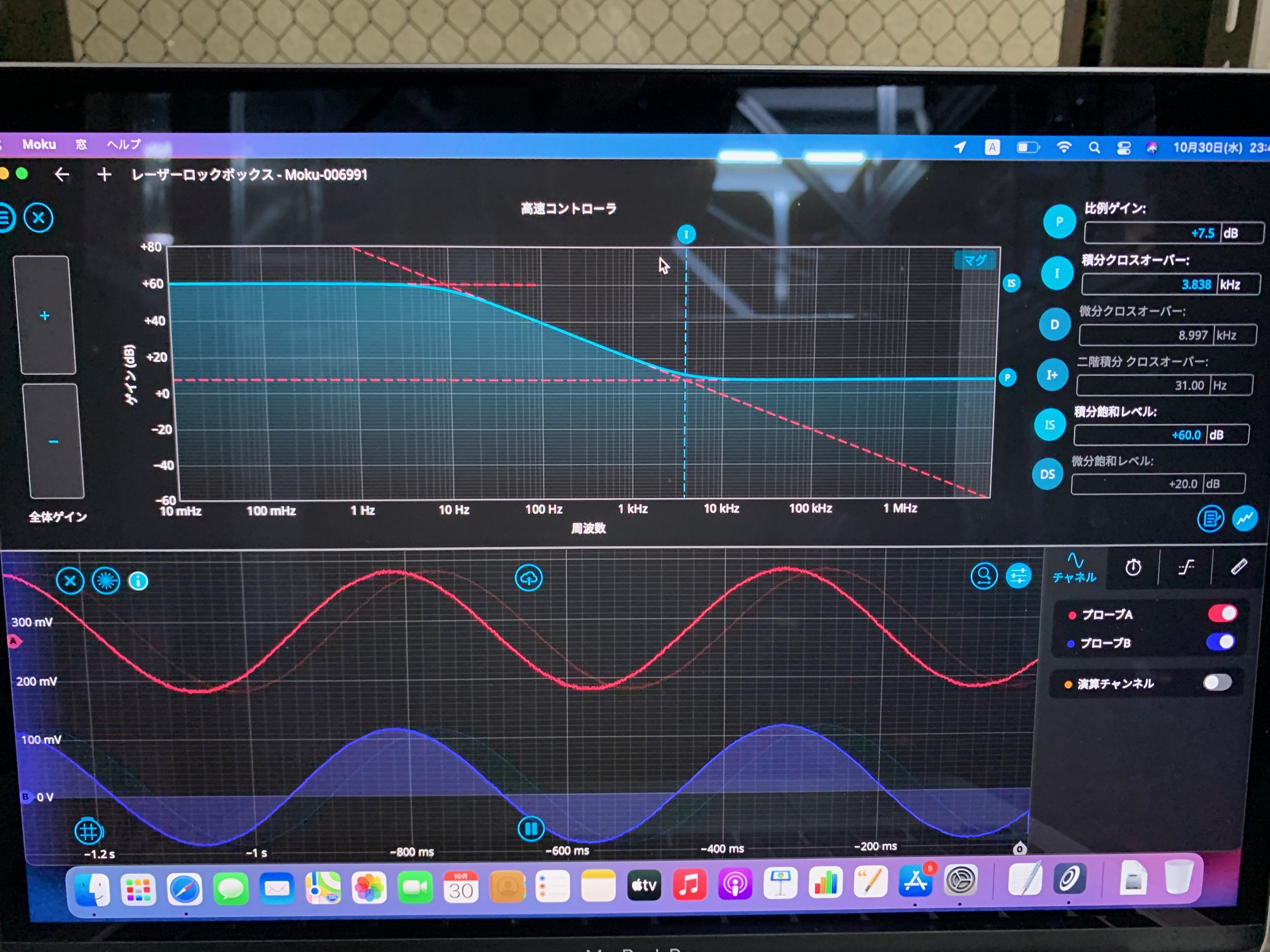
4-7) Settings of Moku low pass, fast, slow controller and SR560
Nishino
2024.10.30 (see GROLTF_sub/OLTF.ipynb)
I characterized the GR locking loop. UGF is 1.4 kHz with the phase margin of ~80 degrees.
Figures:
1) Open loop transfer function (G)
2) Filters of SR560, Moku PID controller, and PZT driver (F)
3) G/F=AH, A: PZT actuator efficiency, H: optical gain
4) Settings of SR560
5) Settings of Moku PID controller.
I recovered bright alignment beam and local oscillator alignment to the homodyne detector. The homodyne detector shot noise is ok (-132 dBVrms/rtHz at 2.2 mW LO injection) but has some 50 Hz line presence so power cables should be checked.
BAB and ppol to OPO
I realigned BAB and ppol to OPO to about 87% mode matching. ppol is aligned from OPO TRANSMISS IN on the servo, BAB from the "stick" power meter in transmission of the OPO set to HI BW and range 8.8 mW. Then I optimized the ppol frequency and OPO temperature by locking OPO for ppol and maximizing the transmission of BAB with the power meter still in place. The optimal settings without green are 7.120 kOhm OPO temperature (from 7.118 kOhm before) and 245-250 MHz ppol PLL frequency (same as before, OPO generally is not hugely sensitive to this parameter). The transmitted BAB power through the OPO is 346 µW (79.2 mV on oscilloscope when power meter is set to 8.8 mW range).
Homodyne balance
I balanced the homodyne using the usual method - lock IRMC, block IR transmission through OPO. Tweak the lens near to IRMC to maximize HOM SUB DC on oscilloscope and tweak the lens further from IRMC to minimize HOM SUB DC. These steps are just to prevent clipping of the beam on the homodyne aperture. Then, adjust the input beam splitter in yaw to balance the homodyne (average level 0 V).
Homodyne noise
I checked the homodyne shot noise. At 2.2 mW IRMC transmission (LO power) I see -132 dBVrms/rtHz which is basically the nominal level. In full span (102.4 kHz) it looks flat, but at 6 kHz span there is a lot of 50 Hz peaks. Checking homodyne shot noise with all of the lights off gives not a huge amount of difference for LO shot noise so it is probably a power supply issue. I should check the plugs (next time).
Homodyne dark noise floor is about -155 dBVrms/rtHz, so more than 20 dB clearance below shot noise, but has a lot of 50 Hz peaks as well. The spectrum analyzer noise (put 50 Ohm terminator in the measurement channel) is about -164 dBm.
Misc
ppol PLL lock still bounces a lot - it will unlock then quickly relock. I noticed that it's less "bouncy" if you place the peak (by ppol laser temperature adjustment) about 15-20 MHz above the target frequency. I guess this has something to do with the "gain/bandwidth" (technically charge pump and timeout counter) of the PLL phase frequency detector.
Nishino,
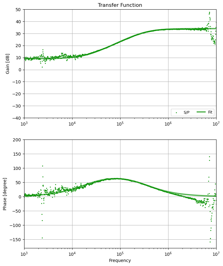
2024.10.29 (TF3)
Estimated loss is 240 ppm this time. I guess it's because the PCC length was detuned from the opimal case.
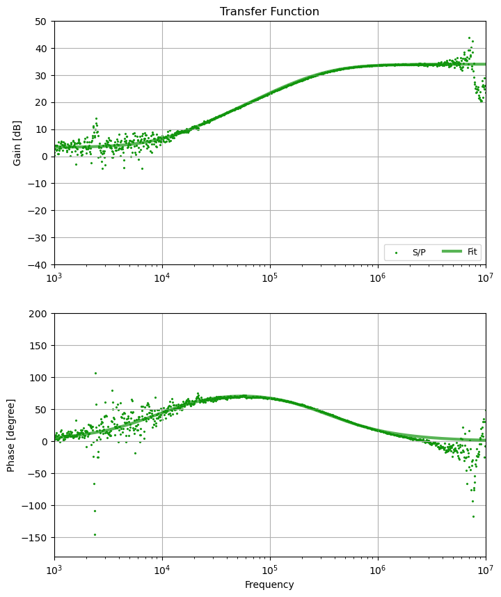
Nishino,
2024.10.28 (see TF5)
I locked all degrees of freedom and measured the speed transfer function for the first time.
The total loss is estimated as 150 ppm.
I checked alignment of ppol to OPO. It was a bit bad (maybe 80% mode matching, fig 1). I realigned to 86.2% (fig 2). It seems in the past the alignment of ppol to OPO was never really that critical anyway.
Since the laser was just activated, the ppol lock was not so stable - this is normal for about 2 hours after laser activation. ppol PLL quite regularly unlocks and relocks when the laser is warming up but it seems to go back to normal after a while.
There is some odd behaviour where sometimes if I touch the steering mirrors a small amount there is an extra mode which flashes on and off. Normally the main ppol mode isn't that sensitive to the steering mirror tuning. Also in transmission of OPO I can see some flashing on the sensor card, displaced about 5mm in yaw from the TEM00 mode.
I looked a bit at BAB and it seems also ok, maybe just a small tweak. But I didn't touch it or take a picture yet.
There has been a long running issue with IRMC lock ever since the main laser EOM was switched from 15 MHz to 88.3 MHz. Before, the error signal was acquired with a TAMA 15 MHz resonant PD but we since switched to a Thorlabs PDA05CF2 broadband RFPD with 75 MHz linewidth. From old logs, the error signal was about 1Vpp before the change and decreased to 100 mV after changing to new modulation scheme. However, the SHG underwent the same change and only saw a factor of 4 decrease in error signal. Initially I though there was some issue with weak IRMC modulation or demodulation signal due to weakening local oscillator synthesis from DDS, but the SHG uses the same mod/demod electronics and works mostly fine so that isn't the main problem.
We currently inject about 2.5 - 3 mW IR to IRMC with the goal of about 2 mW transmission on resonance. So off resonance about 3 mW makes it to IRMC REFL, which is a bit much for the PD. For whatever reason, at some point there was a weak ND filter Thorlabs ND03A, which resulted in a base level of > 5 V on the reflection spectrum (fig 1). With the PD close to saturation, the side spikes of the PDH signal become very small (fig 2). I changed the ND filter to Thorlabs ND1 which is what it was a while ago, which gives a base level of about 2.0 V and dip of 1.3 V (fig 3). This makes the error signal have the usual PDH shape but it also became quite small, ~ 70 mVpp.
I checked the PDH sidband amplitude by manually putting the IRMC near resonance (servo scan amplitude zero and PZT HVD offset adjusted to make the reflection signal drop by 1.3 V). I could see the 88 MHz sideband from IRMC REFL RF was about -27 dBm. I sent it to a spare RF amplifier port on the rack +18 dB and could see that the sideband was amplified to maximum -8 dBm. The error signal becomes 400 mVpp (fig 4). I adjusted the cable length a bit to improve the demodulation phase and now the IRMC can automatically lock quite stably. IRMC transmission is about 2.16 mW.
For now this is reasonable to operate. There is some issue with the servo electronics that is reducing the signal. One fix we discussed a while ago with Yuhang and Pierre Prat is to replace resistor R33 in the servo schematic (feedback resistor of an inverting op amp) with a ten times higher resistance to increase the op amp gain 10x. Also I think we could use a *slightly* weaker ND filter on IRMC REFL RF. Could also make an 88 MHz resonant PD but maybe that's too much effort. For now it's fine, we still have spare RF amplifier ports so we don't need to mess with it until we need those for other things.
Next:
- measure IRMC tansfer function and optimise UGF
- recover BAB alignment to OPO and homodyne
- optimise green alignment to OPO via BAB nonlinear gain
[Shalika, Katsuki]
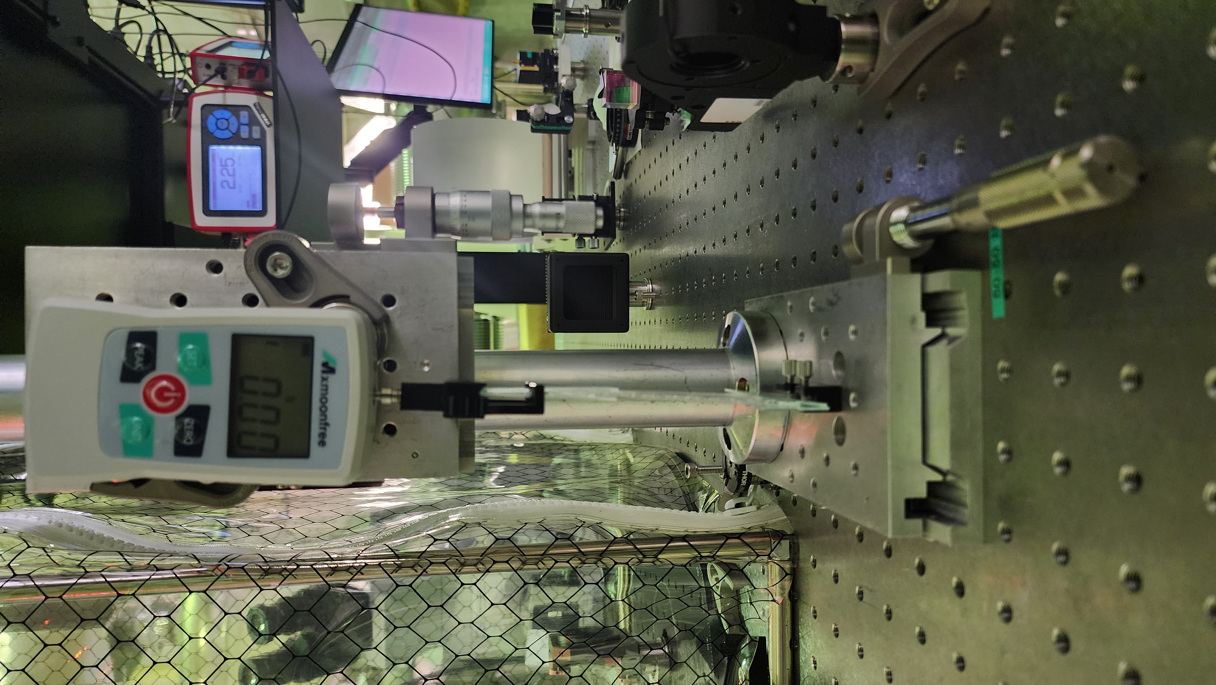
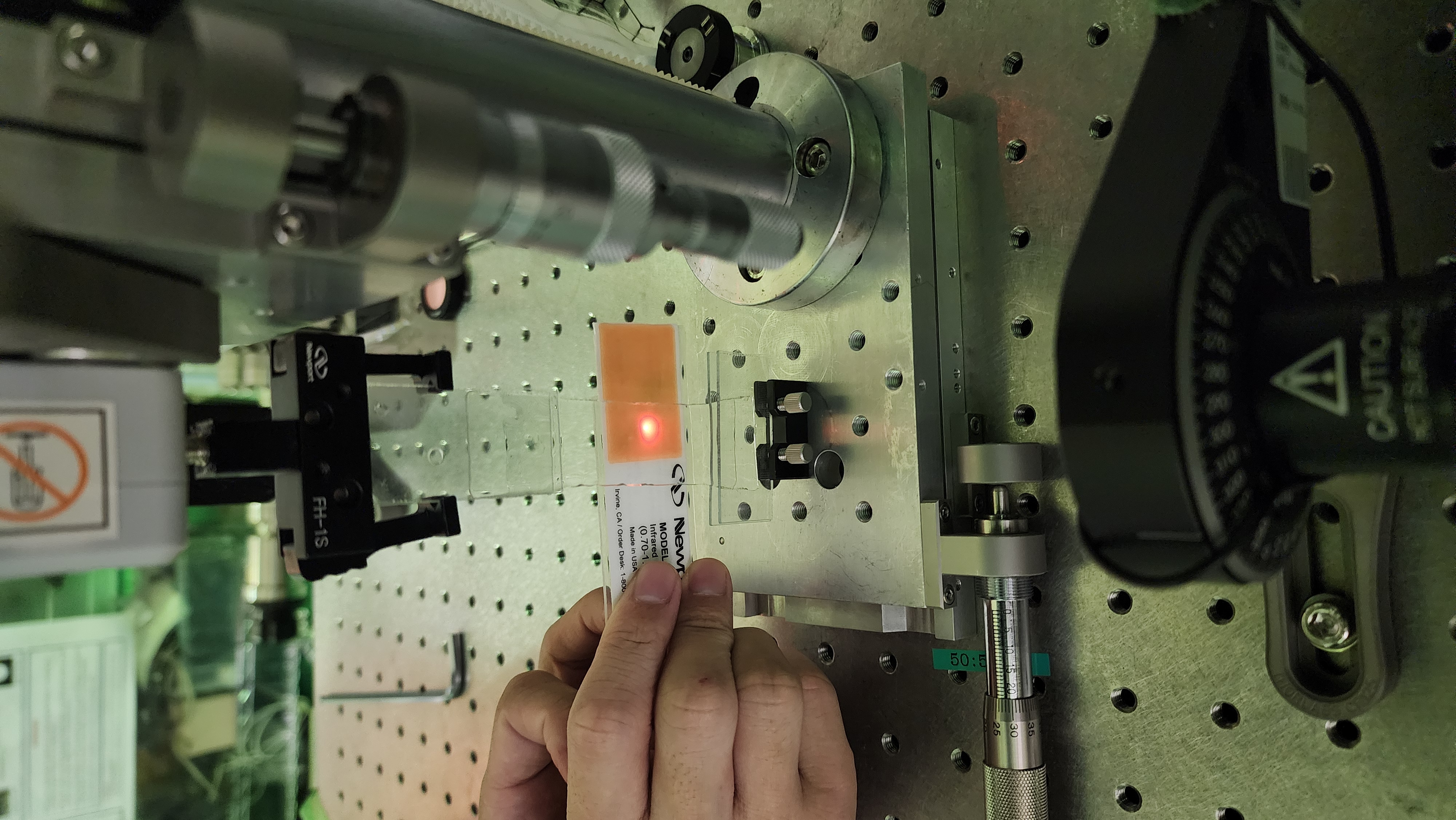
Both hydrogel and force gauge are on translation stage. We moved the force gauge up using the actuator on translation stage.See Fig 1 and Fig 2.
hydrogel is 8-9cm in length and 1.5mm thick. Each measurement take 2:30 mins
The laser is at center
0.26 N
C:\Users\atama\Dropbox\Cell Birefringence\Measurement data\hydrogel\Force gauge v2\Fri, Oct 25, 2024 4-02-01 PM.txt
0.28
C:\Users\atama\Dropbox\Cell Birefringence\Measurement data\hydrogel\Force gauge v2\Fri, Oct 25, 2024 4-06-13 PM.txt
0.30
C:\Users\atama\Dropbox\Cell Birefringence\Measurement data\hydrogel\Force gauge v2\Fri, Oct 25, 2024 4-09-53 PM.txt
0.32 N
C:\Users\atama\Dropbox\Cell Birefringence\Measurement data\hydrogel\Force gauge v2\Fri, Oct 25, 2024 4-13-41 PM.txt
0.34 N
C:\Users\atama\Dropbox\Cell Birefringence\Measurement data\hydrogel\Force gauge v2\Fri, Oct 25, 2024 4-18-30 PM.txt
0.36
C:\Users\atama\Dropbox\Cell Birefringence\Measurement data\hydrogel\Force gauge v2\Fri, Oct 25, 2024 4-22-30 PM.txt
0.38
C:\Users\atama\Dropbox\Cell Birefringence\Measurement data\hydrogel\Force gauge v2\Fri, Oct 25, 2024 4-26-43 PM.txt
0.40
C:\Users\atama\Dropbox\Cell Birefringence\Measurement data\hydrogel\Force gauge v2\Fri, Oct 25, 2024 4-30-35 PM.txt
0.42 N
C:\Users\atama\Dropbox\Cell Birefringence\Measurement data\hydrogel\Force gauge v2\Fri, Oct 25, 2024 4-34-02 PM.txt
0.44
C:\Users\atama\Dropbox\Cell Birefringence\Measurement data\hydrogel\Force gauge v2\Fri, Oct 25, 2024 4-37-43 PM.txt
0.46
Fri, Oct 25, 2024 4-41-56 PM
0.48
C:\Users\atama\Dropbox\Cell Birefringence\Measurement data\hydrogel\Force gauge v2\Fri, Oct 25, 2024 4-46-00 PM.txt
0.50
C:\Users\atama\Dropbox\Cell Birefringence\Measurement data\hydrogel\Force gauge v2\Fri, Oct 25, 2024 4-50-26 PM.txt
we moved the hydrogel laterally--the beam is not in center
0.51
C:\Users\atama\Dropbox\Cell Birefringence\Measurement data\hydrogel\Force gauge v2\Fri, Oct 25, 2024 4-54-17 PM.txt
0.48
C:\Users\atama\Dropbox\Cell Birefringence\Measurement data\hydrogel\Force gauge v2\Fri, Oct 25, 2024 4-59-40 PM.txt
0.46
C:\Users\atama\Dropbox\Cell Birefringence\Measurement data\hydrogel\Force gauge v2\Fri, Oct 25, 2024 5-03-11 PM.txt
0.44
C:\Users\atama\Dropbox\Cell Birefringence\Measurement data\hydrogel\Force gauge v2\Fri, Oct 25, 2024 5-06-56 PM.txt
0.42
C:\Users\atama\Dropbox\Cell Birefringence\Measurement data\hydrogel\Force gauge v2\Fri, Oct 25, 2024 5-11-10 PM.txt
0.40
C:\Users\atama\Dropbox\Cell Birefringence\Measurement data\hydrogel\Force gauge v2\Fri, Oct 25, 2024 5-17-25 PM.txt
0.38
C:\Users\atama\Dropbox\Cell Birefringence\Measurement data\hydrogel\Force gauge v2\Fri, Oct 25, 2024 5-21-26 PM.txt
0.36
C:\Users\atama\Dropbox\Cell Birefringence\Measurement data\hydrogel\Force gauge v2\Fri, Oct 25, 2024 5-24-52 PM.txt
0.34
C:\Users\atama\Dropbox\Cell Birefringence\Measurement data\hydrogel\Force gauge v2\Fri, Oct 25, 2024 5-29-02 PM.txt
0.32
C:\Users\atama\Dropbox\Cell Birefringence\Measurement data\hydrogel\Force gauge v2\Fri, Oct 25, 2024 5-32-51 PM.txt
The hydrogel maybe is a bit dry. So, the 0.32 was the minimum the translation stage could move.
We moved the hydrogel laterally to another side.
0.32
C:\Users\atama\Dropbox\Cell Birefringence\Measurement data\hydrogel\Force gauge v2\Fri, Oct 25, 2024 5-41-43 PM.txt
0.36
C:\Users\atama\Dropbox\Cell Birefringence\Measurement data\hydrogel\Force gauge v2\Fri, Oct 25, 2024 5-45-22 PM.txt
we stop coz the force change by itself.
the results (birefringence and diattenuation) for both points are attached.
Fig 1 , 2 - point where laser is at center
Fig 3, 4 - point where laser is on one side (not center)
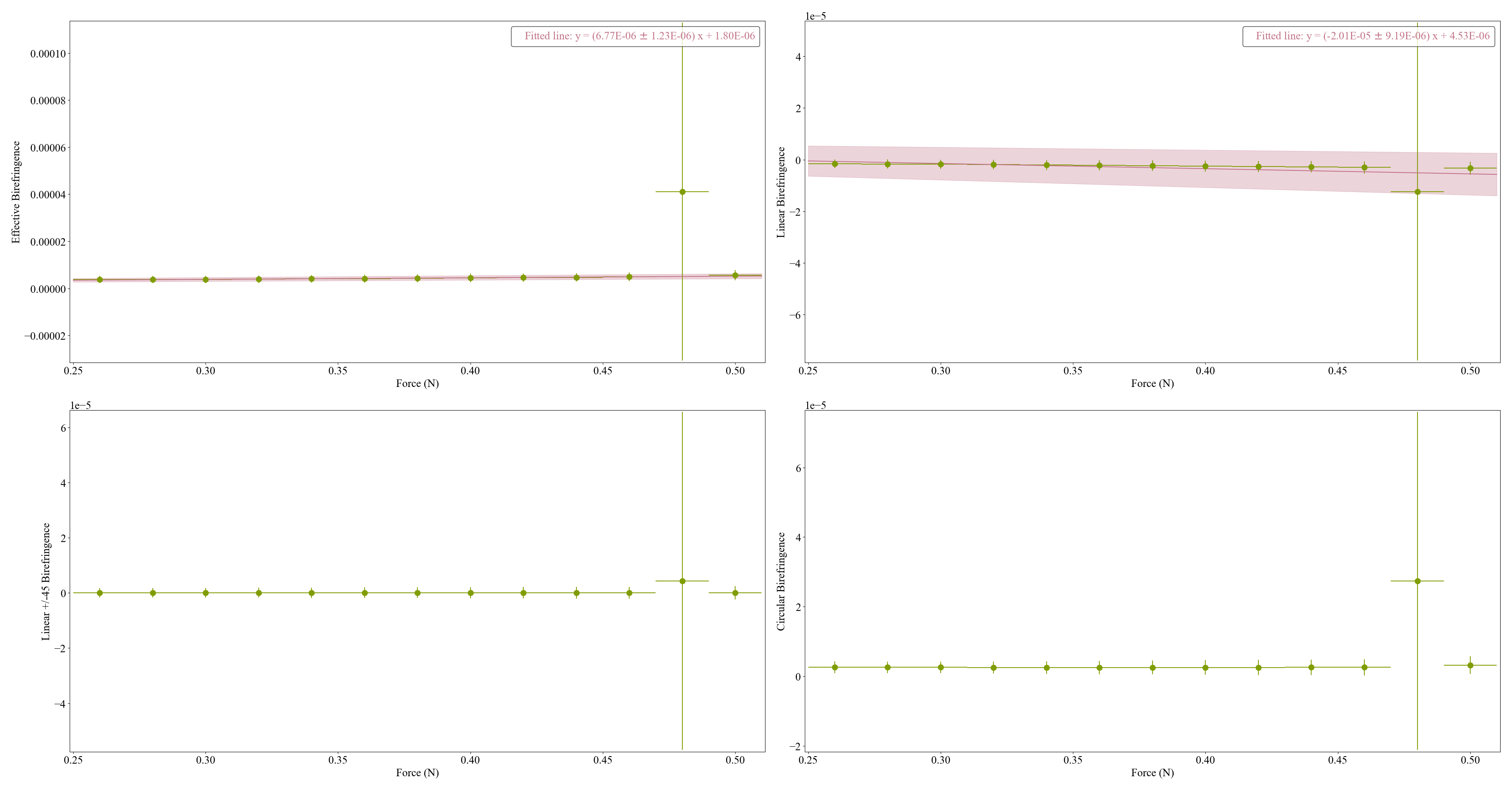
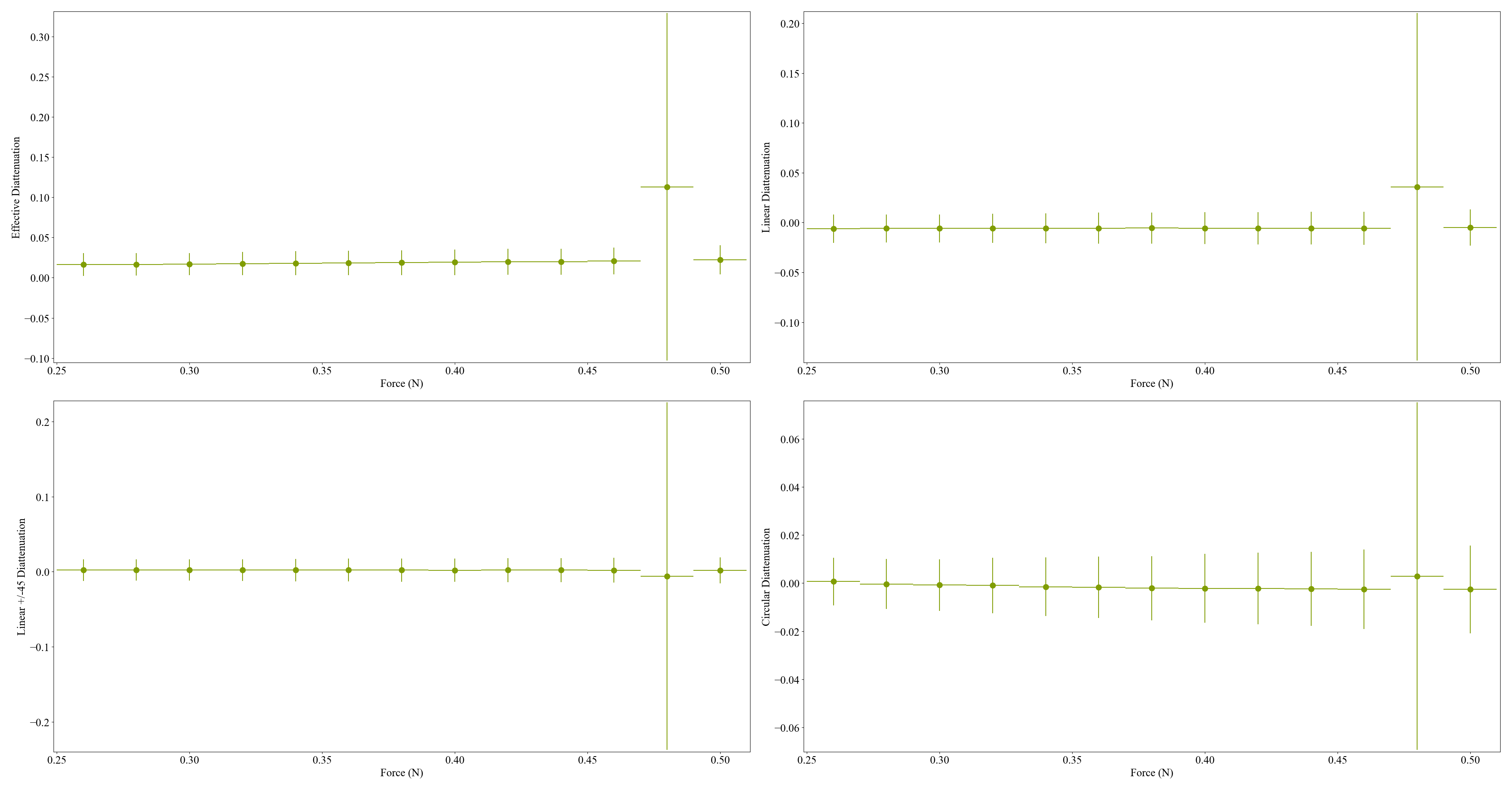
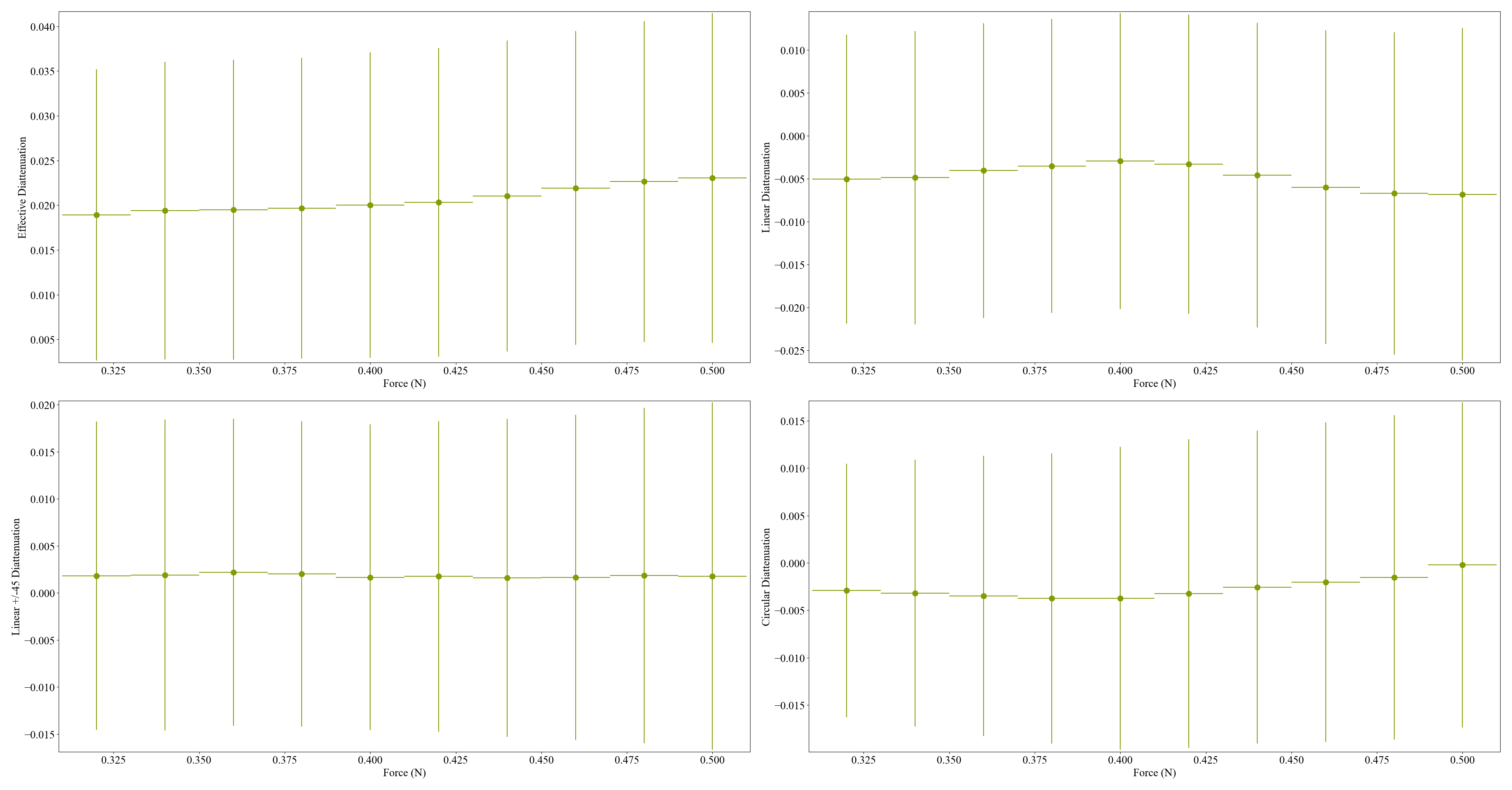
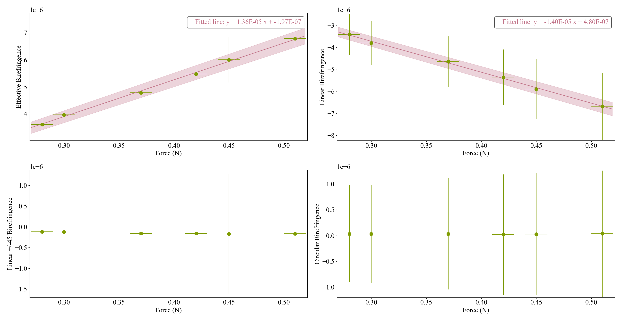
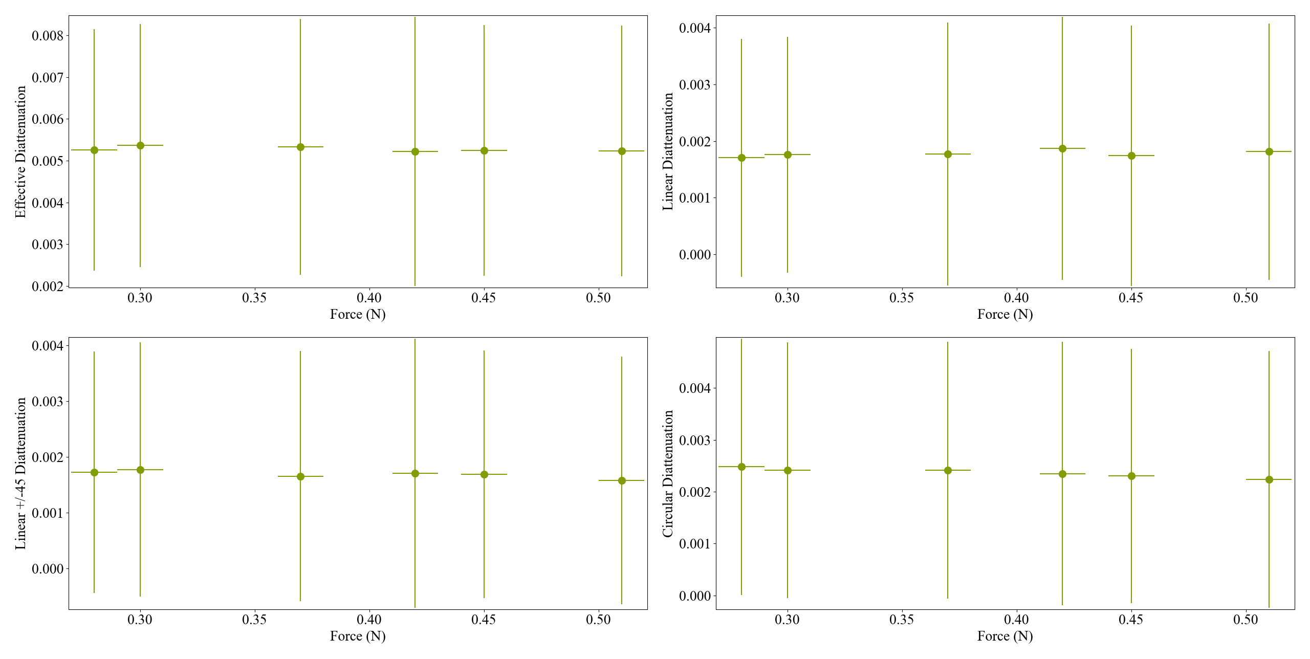
The analysis done only for the 2nd hydrogel (the one which was measured after the first one broke). The point with force 0N is omitted, since the actual 0N should be the point of start of seeing the force change. The birefringence was measured at 2 points
Fig1:Birefringence vs Force of point 1
Fig 2: Diattenuation vs Force of point 1
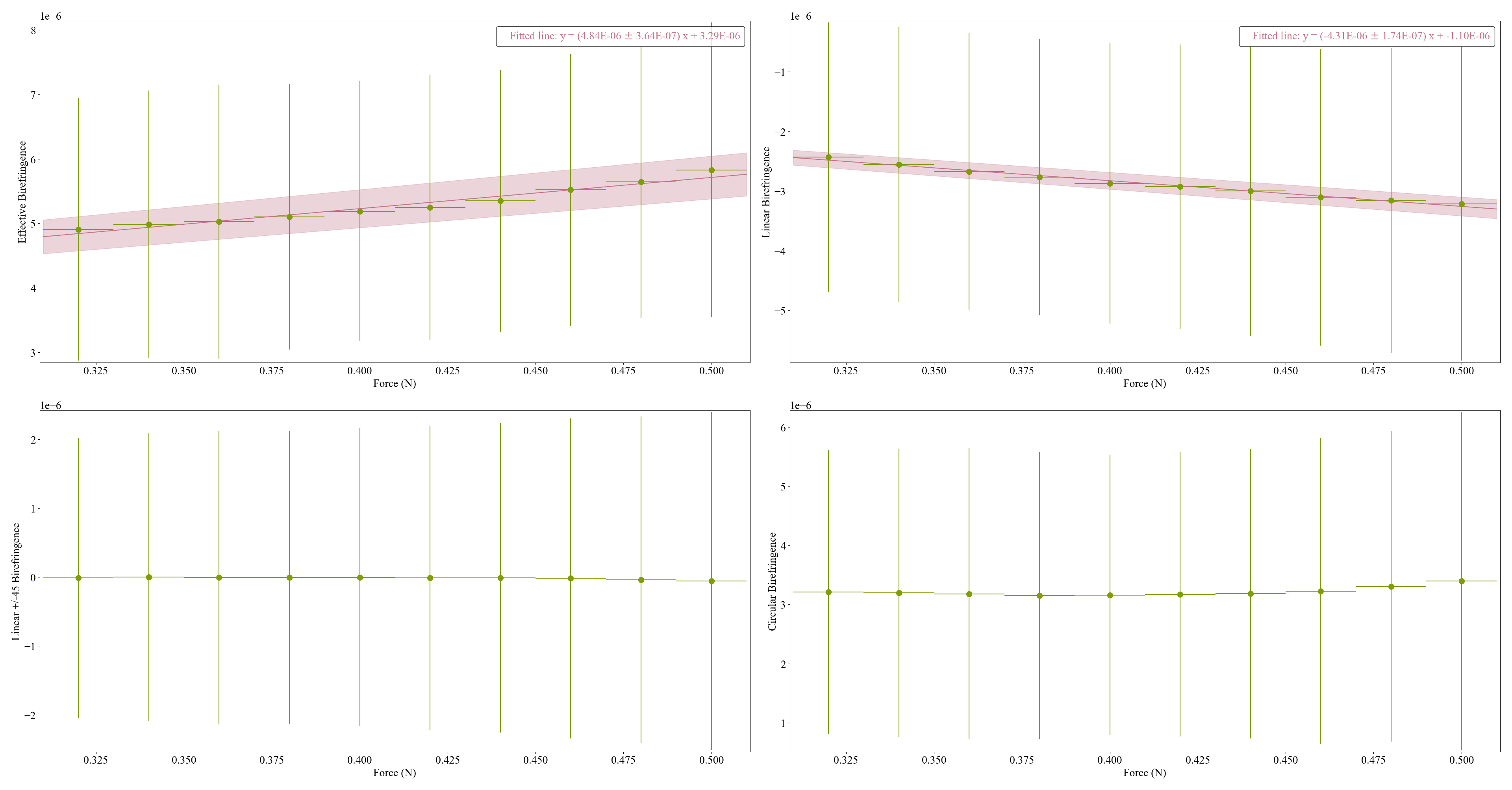
Fig 3:Birefringence vs Force of point 2
Fig 4: Diattenuation vs Force of point 2
The number plotted is the median obtained from the data at each force value.
Update 1: I changed the plot becauase I had previously overconverted rad to rad, assuming it was degrees.
Update 2: Added Error bar to fitted data
with BS removed, I aligned the BB1EO3 at 45 degree. This is to check if Polarization ray tracing analysis is correct for coatings.
LC goes from 0-3.5V with 0.1V step and 100 averaging
C:\Users\atama\Dropbox\LC-Experiment\Measurement Data\Birefringence Measurements\Coating measurement\BB1-E03\20241022\Tue, Oct 22, 2024 3-37-46 PM.txt
[Katsuki, Shalika, Marc]
1.5 mm hydrogel, recipe same as previous. The error on force can be ±0.01 N. The measurement is taken in transmission of LC without BS.
20 avg, 0.5V-3V with 0.25V
0 N
C:\Users\atama\Dropbox\Cell Birefringence\Measurement data\hydrogel\Force gauge v2\Mon, Oct 21, 2024 5-15-53 PM.txt
0.28 N
C:\Users\atama\Dropbox\Cell Birefringence\Measurement data\hydrogel\Force gauge v2\Mon, Oct 21, 2024 5-22-16 PM.txt
0.31 N
C:\Users\atama\Dropbox\Cell Birefringence\Measurement data\hydrogel\Force gauge v2\Mon, Oct 21, 2024 5-27-33 PM.txt
0.36 N
C:\Users\atama\Dropbox\Cell Birefringence\Measurement data\hydrogel\Force gauge v2\Mon, Oct 21, 2024 5-31-40 PM.txt
0.41 N
C:\Users\atama\Dropbox\Cell Birefringence\Measurement data\hydrogel\Force gauge v2\Mon, Oct 21, 2024 5-36-20 PM.txt
hydrogel broke -- Also, there could be an issue of hydrogel breaking due to it getting dried. So, reduced to 10 avg for faster measurement.
0 N
C:\Users\atama\Dropbox\Cell Birefringence\Measurement data\hydrogel\Force gauge v2\Mon, Oct 21, 2024 5-44-04 PM.txt
0.28 N
C:\Users\atama\Dropbox\Cell Birefringence\Measurement data\hydrogel\Force gauge v2\Mon, Oct 21, 2024 5-47-38 PM.txt
0.30 N
C:\Users\atama\Dropbox\Cell Birefringence\Measurement data\hydrogel\Force gauge v2\Mon, Oct 21, 2024 5-50-56 PM.txt
0.37 N
C:\Users\atama\Dropbox\Cell Birefringence\Measurement data\hydrogel\Force gauge v2\Mon, Oct 21, 2024 5-54-23 PM.txt
0.42 N
C:\Users\atama\Dropbox\Cell Birefringence\Measurement data\hydrogel\Force gauge v2\Mon, Oct 21, 2024 5-58-02 PM.txt
0.45
C:\Users\atama\Dropbox\Cell Birefringence\Measurement data\hydrogel\Force gauge v2\Mon, Oct 21, 2024 6-02-41 PM.txt
0.51
C:\Users\atama\Dropbox\Cell Birefringence\Measurement data\hydrogel\Force gauge v2\Mon, Oct 21, 2024 6-06-23 PM.txt
we moved the translation stage by (23.2-20.2) cm
0.51 N
C:\Users\atama\Dropbox\Cell Birefringence\Measurement data\hydrogel\Force gauge v2\Mon, Oct 21, 2024 6-12-19 PM.txt
0.45 N
C:\Users\atama\Dropbox\Cell Birefringence\Measurement data\hydrogel\Force gauge v2\Mon, Oct 21, 2024 6-15-46 PM.txt
0.42 N
C:\Users\atama\Dropbox\Cell Birefringence\Measurement data\hydrogel\Force gauge v2\Mon, Oct 21, 2024 6-20-16 PM.txt
0.37 N
C:\Users\atama\Dropbox\Cell Birefringence\Measurement data\hydrogel\Force gauge v2\Mon, Oct 21, 2024 6-23-50 PM.txt
0.31 N
C:\Users\atama\Dropbox\Cell Birefringence\Measurement data\hydrogel\Force gauge v2\Mon, Oct 21, 2024 6-27-47 PM.txt
0.28 N
C:\Users\atama\Dropbox\Cell Birefringence\Measurement data\hydrogel\Force gauge v2\Mon, Oct 21, 2024 6-31-09 PM.txt
0 N
C:\Users\atama\Dropbox\Cell Birefringence\Measurement data\hydrogel\Force gauge v2\Mon, Oct 21, 2024 6-34-17 PM.txt
Input without any sample
C:\Users\atama\Dropbox\Cell Birefringence\Measurement data\hydrogel\Force gauge v2\Mon, Oct 21, 2024 6-37-59 PM.txt
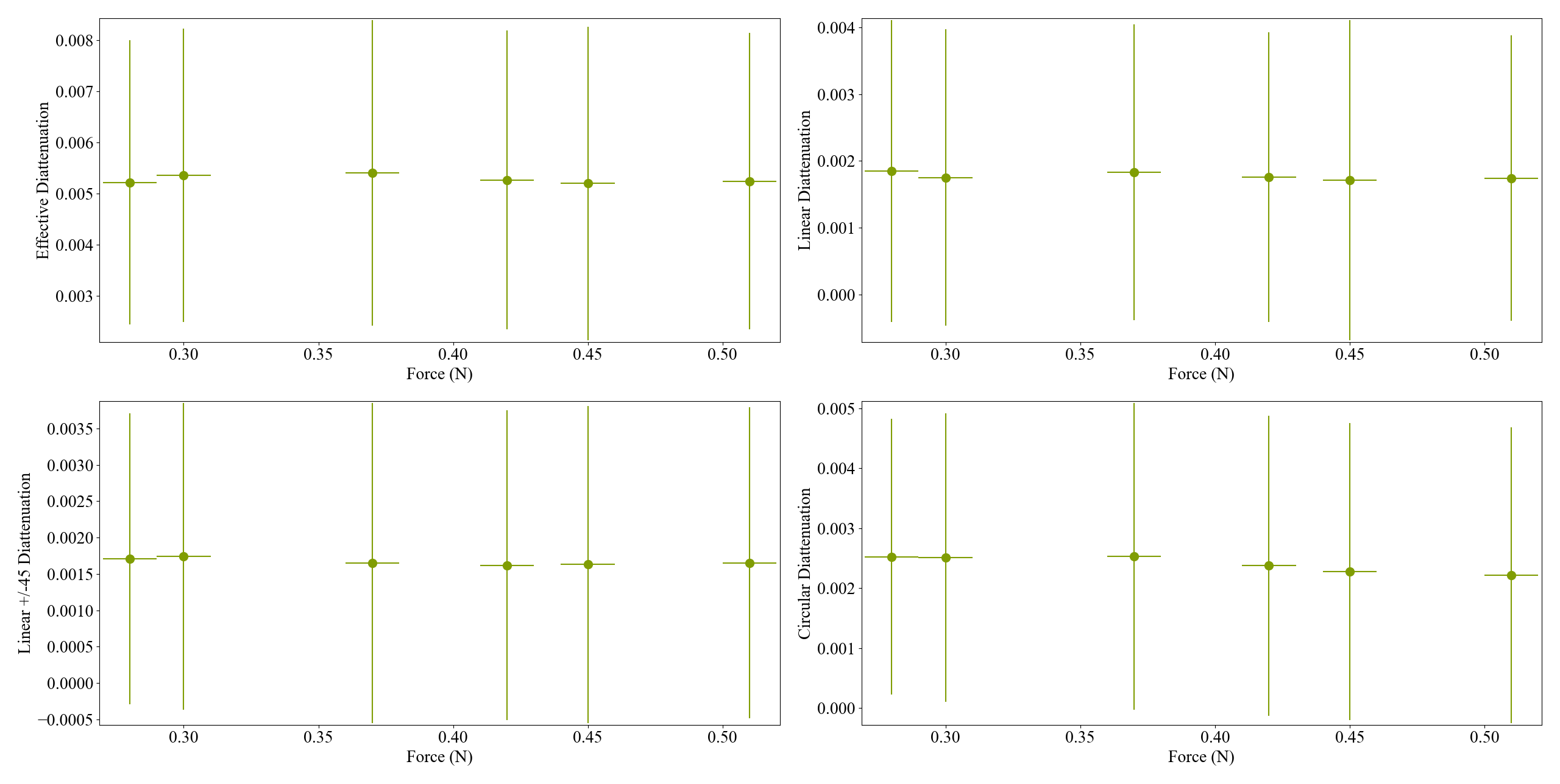
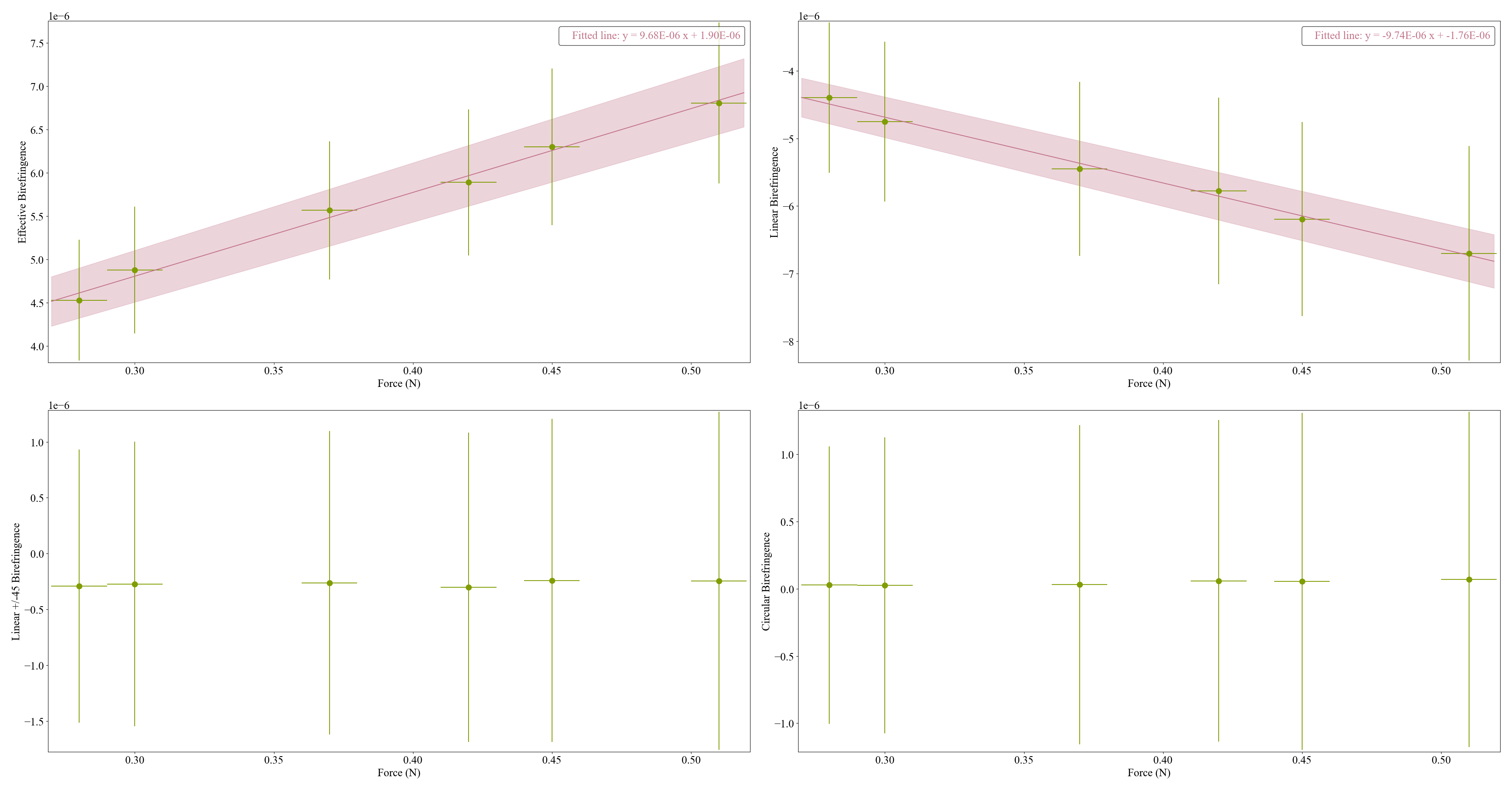
The analysis done only for the 2nd hydrogel (the one which was measured after the first one broke). The point with force 0N is omitted, since the actual 0N should be the point of start of seeing the force change. The birefringence was measured at 2 points
Fig1:Birefringence vs Force of point 1
Fig 2: Diattenuation vs Force of point 1
Fig 3:Birefringence vs Force of point 2
Fig 4: Diattenuation vs Force of point 2
The number plotted is the median obtained from the data at each force value.
Update 1: I changed the plot becauase I had previously overconverted rad to rad, assuming it was degrees.
Update 2: Added Error bar to fitted data
Nishino
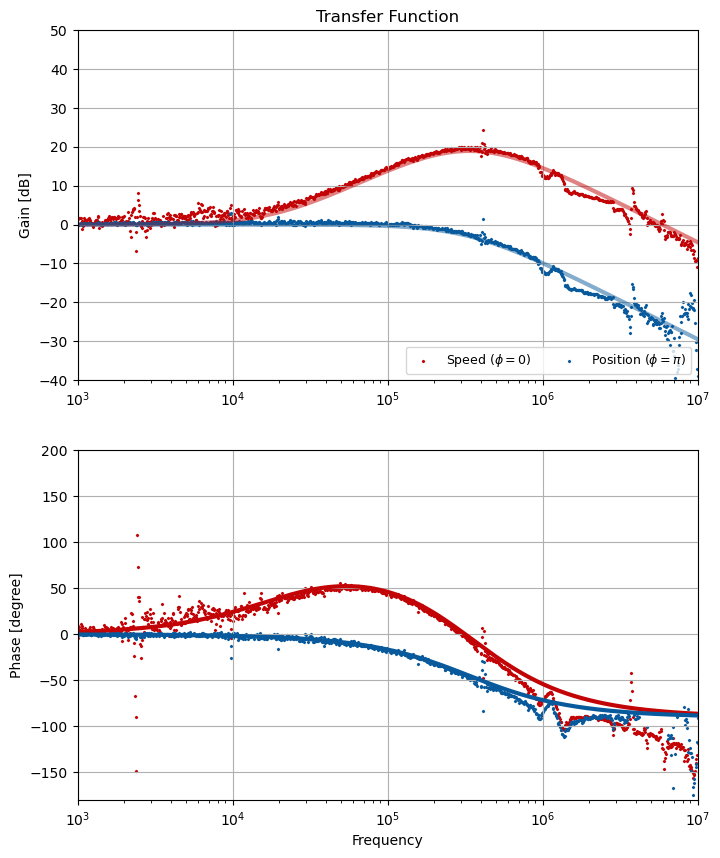
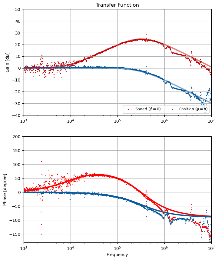
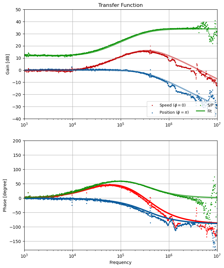
In my calculation, the best PCC round-trip phase is 1) when the transmittance light from ETM gets maximum AND 2) monitoring the transmittance light from the PCM, the relative angle between the signal and main beam becomes pi/4.
Adjusting the PCC angle to meet 1) and the signal beam angle to meet 2) condition by hand, I obtained the result shown in Fig. 2). Red is the speed state and blue is the position state. Somehow it behaves weird at high-frequencies but taking their ratio (green) it could be fitted well with a model. I guess the photo-detetor calibration went wrong for some reason.
I rotated BS to align the arrows with the beam propagation direction.
BS Font face
C:\Users\atama\Dropbox\LC-Experiment\Measurement Data\Birefringence Measurements\Beam Splitter Calibration\20241006\front_refl\Tue, Oct 8, 2024 5-18-51 PM.txt
C:\Users\atama\Dropbox\LC-Experiment\Measurement Data\Birefringence Measurements\Beam Splitter Calibration\20241006\front_trans\Tue, Oct 8, 2024 6-59-48 PM.txt
The large birefringence(23 deg) in reflection was confusing. So, alignment was improved more. Redid measurement in reflection of BS front face.
C:\Users\atama\Dropbox\LC-Experiment\Measurement Data\Birefringence Measurements\Beam Splitter Calibration\20241009\front_refl\Wed, Oct 9, 2024 10-26-57 PM.txt
I mounted mirror(BB1EO3 sample 1) in the transmission of the BS front face. The mirror is aligned to obtain reflection at optimal position. Then I flipped BS. This was to ensure that in case the BS moved, I can understand that its from BS flipping and not mirror misalignment. After flipping BS, the beam maintained its position after reflection from coating. We don't care about the reflection from the back face of the BS anymore.
Polarization states generated with BS back face transmission:
C:\Users\atama\Dropbox\LC-Experiment\Measurement Data\Polarization states\20241010\Thu, Oct 10, 2024 4-20-30 PM.txt
In the reflection of the mirror, after BS:
C:\Users\atama\Dropbox\LC-Experiment\Measurement Data\Birefringence Measurements\Coating measurement\BB1-E03\20241010\Thu, Oct 10, 2024 5-40-42 PM.txt
Also, the measurement takes only 1 hour. Maybe it improved sometime from labview modifications. I never noted the time of measurements after the 1st labview was made, which was taking rather 2 hrs.
Nishino,
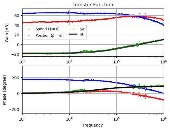
I measured transfer functions of the speed and position meter. The PCC is not locked but just scan the PCM to minimize and maximize the transmittance light which is a consequence of interference between the first and second circulation light.
The result is shown in the figure. Blue is the position state and red is speed state. Their ratio is fitted with a function with a cavity loss of 500 ppm.
with 1 mm step size, 14mm radius
Input = ['Fri, Oct 11, 2024 11-36-41 AM.txt', 'Fri, Oct 11, 2024 1-34-57 PM.txt' , 'Fri, Oct 11, 2024 2-13-44 PM.txt' , 'Fri, Oct 11, 2024 2-51-14 PM.txt' , 'Fri, Oct 11, 2024 3-41-43 PM.txt' , 'Fri, Oct 11, 2024 4-52-41 PM.txt']
iLM/LMA ; white dot placed on top toward laser source
Output = ['Fri, Oct 11, 2024 11-40-34 AM.txt' , 'Fri, Oct 11, 2024 1-36-56 PM.txt', 'Fri, Oct 11, 2024 2-17-22 PM.txt' , 'Fri, Oct 11, 2024 2-53-16 PM.txt' , 'Fri, Oct 11, 2024 3-46-31 PM.txt' , 'Fri, Oct 11, 2024 4-55-02 PM.txt']
AZTEC 30mm number 1 (number is attributed randomly by me).
Output = ['Tue, Oct 15, 2024 10-21-16 AM.txt' , 'Tue, Oct 15, 2024 9-45-08 AM.txt' , 'Fri, Oct 11, 2024 9-05-53 PM.txt' , 'Fri, Oct 11, 2024 8-26-53 PM.txt' , 'Fri, Oct 11, 2024 7-53-34 PM.txt', 'Fri, Oct 11, 2024 7-17-27 PM.txt']
AZTEC 30mm number 2 (number is attributed randomly by me).
Output = ['Tue, Oct 15, 2024 12-03-02 PM.txt' , 'Tue, Oct 15, 2024 1-20-44 PM.txt' , 'Tue, Oct 15, 2024 2-01-50 PM.txt' , 'Tue, Oct 15, 2024 2-40-34 PM.txt' , 'Tue, Oct 15, 2024 3-27-17 PM.txt' , 'Tue, Oct 15, 2024 4-20-30 PM.txt']