NAOJ GW Elog Logbook 3.2

[Marc, Michael M., Shalika]
Note for future operation of any of the VI is that now only the new added powermeter is recognized by the VI.
If the one in transmission of the sample is used, it takes priority over the new one (likely because it becomes the number '0' powermeter recognized by the pc).
For now the transmission powermeter is turned off.
[Marc, Michael M., Shalika]
The initial implementation of this feature was made by removing the waiting time of the vi.
It led to visible artifact during the motion of the sample.
It was restored to the usual 500ms and resolved the issue.
Somehow, the VI is now faster than before to acquire each point.
Previously the EOM was rotated by 45 degree, and then input polarization was along x axis of lab frame. The modulation depth observed was not that good. This was because the input polarization was parallel to the crystal. The crystal is already rotated by 45degree inside the housing of EOM. So, we we should either rotate the input polarization by 45deg or the EOM. I took the path of least action and rotated the polarization by 45deg using a polarizer.
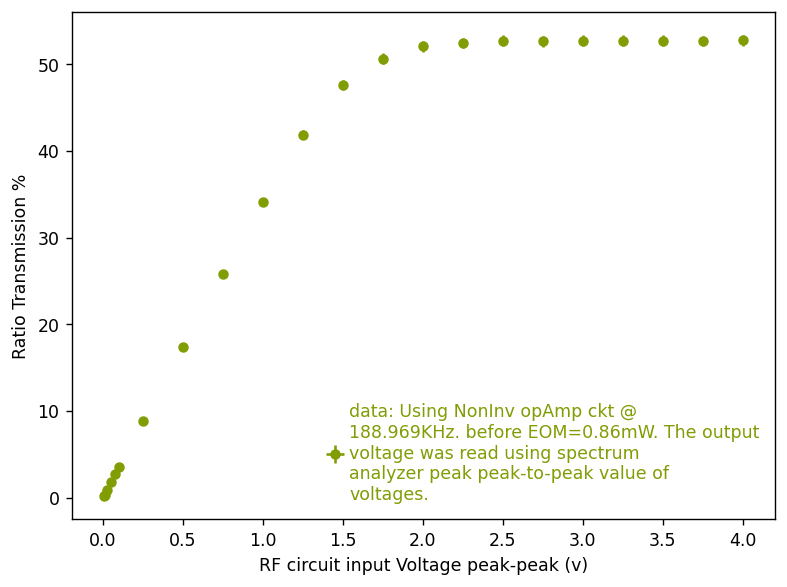
The input polarization was tuned to become circular using QWP, HWP. Then polarizer was installed in rotator mount. I inject for now a 45degree rotated polarization. The power of input pol is now 0.86mW.
The transmission of EOM is 0.85mW. So, transmision is around 98%.
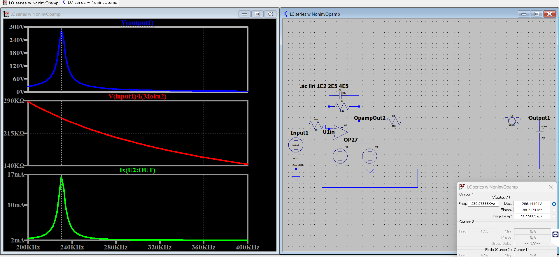
I then apply modulation at 189.969KHz, using a noninverting amplifier circuit from Fig 1. Previously I was using Inv amplifier design, but the matched impedance with moku halves the input voltage. So, I went for a high impedance circuit design using Noninv amplifier. I took into account the losses in the circuit during simulation, which predicts the maximum voltage I have is 286V. I want to install transformer after opamp, to amplify more. If you are impedance matched your circuit will always act as voltage divider circuit, and the input voltage will be halved. A high-z circuit helps achieve no drop in input voltage of the circuit. For our circuit, to ensure minimal reflection, the cable should not be long (1km).
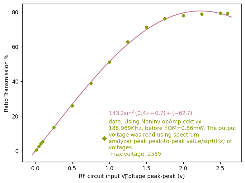
The modulation is observed after a polarizer in cross polarizer configuration, with the input polarizer. The response is shown in Fig 2. The data was noted from the spectrum analzyer as PSD units, Vp-p/sqrt(Hz). I then multplied this value to convert to power using coversion factor of photodiode.
My circuit seems to have saturated after 2.5Vp-p input or so. I need to investigate this. But, the response of the modulation doesn't change after 2.5V.
I use the power ratio to compute the maximum voltage I am reaching now, and it's around 255V.
Data is saved in 'C:\Users\atama\Dropbox\EOM 2D\EOM 1\Characteristics_20250304.txt'
Also, I observed the change in the oscilloscope of values duirng modulation and without modulation. The mean value of voltage remains same as 2.15V. The peak to peak value is the only one which changes.
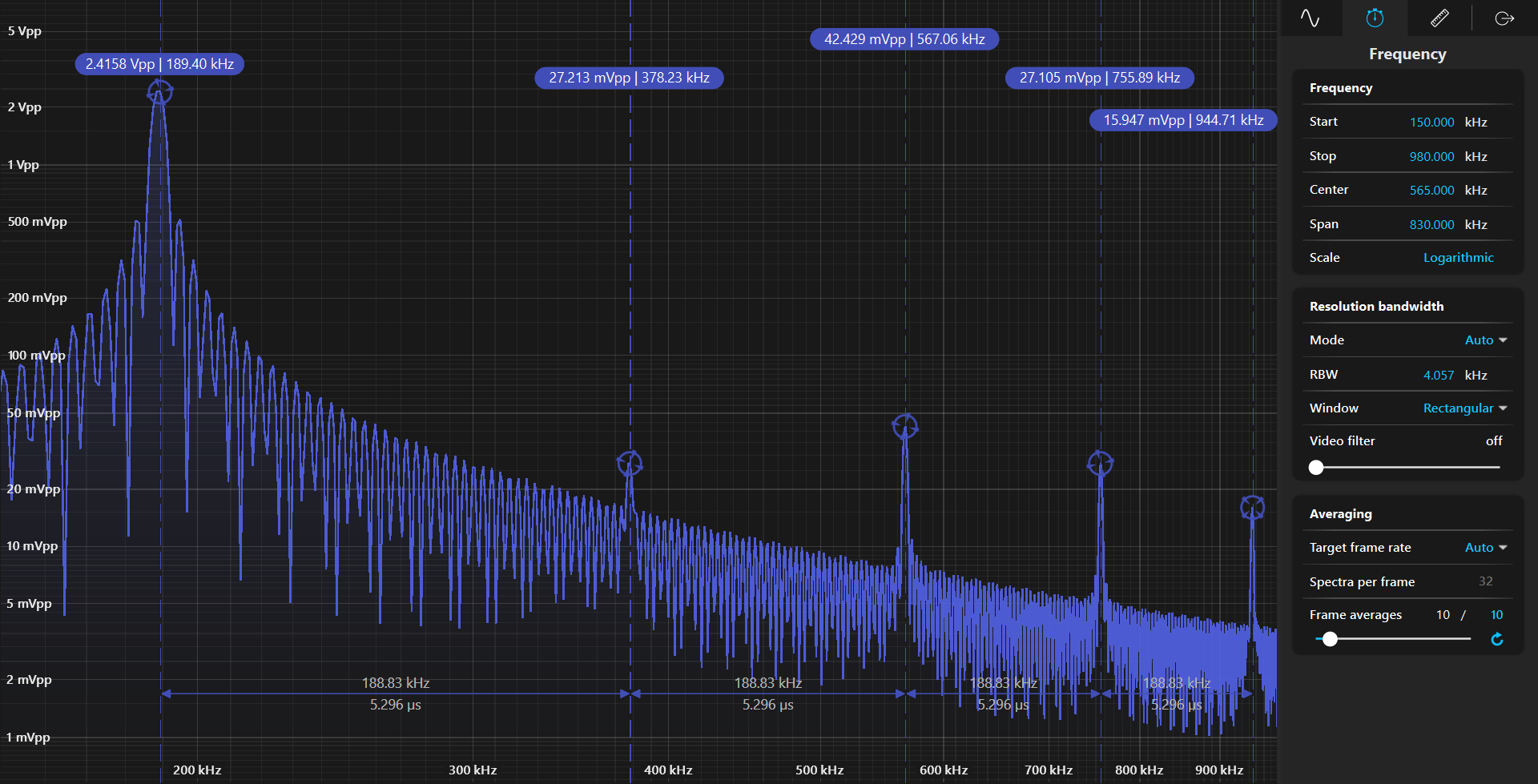
The spectrum of laser modulation at 2.5Vp-p from moku, with harmonics.

Yesterday, I had noted the PSD units of voltage. As the ratio power is Outputpower/Input power, I redid measurements to take into account only Vp-p. In the following plot you can see the saturation after 2.5V or so. ]

Hsun-Chung, Chien-Ming, Michael
The infrared probe and green pump are both mode matched into the OPO cavity. The green steering mirror closest to the OPO was replaced with a PZT phase shifter at 45 degree incidence, like the one in TAMA.
The PDH locking setup was constructed. Originally we were going to use 40 MHz modulation onto the IR probe beam to lock the OPO, but since the IR probe is injected into the high reflectivity M2 mirror, the amount of IR coupling is quite low and the PDH signal is small. Instead we clone the 40 MHz sidebands onto the green beam using the SHG (or rather, SFG - sum frequency generation) and can get good sideband amplitude.
To lock the cavity we planned to use the grey Mokulab from TAMA FC. The Mokulab output was sent to a really old 33 dB RF power amplifier (it has an analogue dial), which works. However, the grey mokulab input ports are not working properly. This was tested by sending a function generator input into the IN ports and checking oscilloscope and spectrum analyzer functions.
So, we need either a working Mokulab unit or PDH locking hardware (currently we do not have sufficient equipment for 40 MHz RF amplification). A long time ago we were using a Red Mokulab in ATC (I think this was purchased using my old JSPS funding or Matteo Kiban A) which seems to have moved on to another experiment right now.
Hsun-Chung and Chien-Ming left today since their flight tomorrow is very early. Since everything is aligned and mode matched, once we get the PDH locking equipment I should be able to do the OPO nonlinear gain test (IR probe amplification and deamplification from a slowly phase modulated green pump injection, at different levels of green power) by myself and infer the threshold power, which is an important number for the squeezer performance.
June-Gyu, Gyo-ik, Hsun-Chung, Chien-Ming, Michael
The local oscillator was aligned to the "mode cleaner" (just a single mode polarization maintaining fiber).
The OPO mirrors were cleaned with First Contact after being glued to the new mounts.
It seems one of the ports on the 3 port HVD in the ATC clean booth might be damaged.
We want to perform the nonlinear gain test so we will need to get the OPO PDH signal. We have a mokulab module in TAMA but I need to find the ipad from somewhere.
The TMP in the west end has stoped in error E050 (Excess tenperature). I found the FAN for the TMP was not working (broken). I stoped the DRY pump as well.

Hsun Chun, Chien Ming, Michael
The incoupling mirror was glued to the new mount.
For constructing the path of the local oscillator to the homodyne, I had to take 4 XY lens mounts from the speedmeter drawers.
I replaced the RP (2015) for theTMP with new DRY pump (NeoDry30G) in the west end. The TMP is running with the DRY pump now.
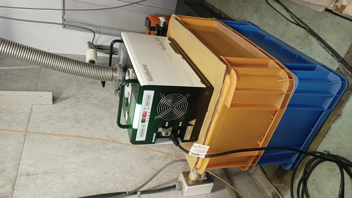
The TMP in the west end has stoped in error E050 (Excess tenperature). I found the FAN for the TMP was not working (broken). I stoped the DRY pump as well.
The maximum Transmisison factor achieved with this circuit was 0.86 or 86%. I can calculate what is roughly the maximum voltage I provided.
Vpi = 306.26V from elog 3750
Vpi * asin(sqrt(0.86)) / 1.5 = 284 V at resonant freq of 189.13 kHz.
Considering the length of transmission line I have as l = 35cm, of R0=50 ohm, I can compute the stray capacitance of the EOM due to the tranmission line as follows:
According to theory written in "Optical Electronics" by Yariv, for a amplitude modulation EOM
TransmissionOut/ Input = sin^2( pi/2 * V/Vpi)
If I can properly, obtain my transfer function measurement then I can very well define my V. Hence, I can estimate the fit parameters better. Also, the quality of fit can then be better estimated by seeing if we have this pi/2 factor inside the sin square function or not.
Currently I am using the voltage input to RF circuit, and not the voltage across the EOM electrodes.
The PCI PC was updated, to be with windows 11. Previously the C drive was full because windows 10 is just bulky. Now the C drive has around 100gb left. This has made the PC much faster than before. It is not buffering anymore.
At first I checked the power of linear polarization (after HWP+QWP) which is incident on EOM. The measurement in oscilloscope of Moku showed 500Vp-p. This is the input power.
Then the photodiode measured the power after EOM in cross polarizer configuration. This was the output power.'
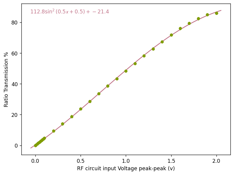
I apply voltage from 0-2Vp-p using Moku to the Opamp circuit. I then obtain the following plot (Fig 1) of Transmission % vs. Voltage. The data is saved in "Characteristics_20250217.txt".
The frequency of the RF circuit was identified by taking In1(from photodiode)/Out1(Input to the RF circuit). I measured the place of resonant frequency using laser.
Interpretation:
That result means the fitting routine found the parameters:
y = 112.8 sin(0.5x+0.5)**2 - 21.4 by using the fit function: A sin (Bx + C) **2 + D
which implies:
-
Amplitude: 112.8, so the sin^2 term varies by 112.8.
-
Frequency: 0.5, meaning the period is
-
Phase shift: 0.5, so the sine's argument is shifted.
-
Offset: -21.4, which makes the minimum value y_{min}=-21.4 (since goes from 0 to 1, the output ranges from 112.8-21.4=91.4).
According to theory written in "Optical Electronics" by Yariv, for a amplitude modulation EOM
TransmissionOut/ Input = sin^2( pi/2 * V/Vpi)
If I can properly, obtain my transfer function measurement then I can very well define my V. Hence, I can estimate the fit parameters better. Also, the quality of fit can then be better estimated by seeing if we have this pi/2 factor inside the sin square function or not.
Currently I am using the voltage input to RF circuit, and not the voltage across the EOM electrodes.
The maximum Transmisison factor achieved with this circuit was 0.86 or 86%. I can calculate what is roughly the maximum voltage I provided.
Vpi = 306.26V from elog 3750
Vpi * asin(sqrt(0.86)) / 1.5 = 284 V at resonant freq of 189.13 kHz.
Considering the length of transmission line I have as l = 35cm, of R0=50 ohm, I can compute the stray capacitance of the EOM due to the tranmission line as follows:
June-gyu Park, Gyo-ik Kim, Chien Ming, Michael
We checked the status of the squeezer layout. The green was slightly misaligned to the OPO but it didn't require much change, and everything else seemed fine. We checked the SHG IR in vs green out, optimizing the PPLN crystal temperature at each different power input. There is a little optimization required at the 3rd significant figure of the temperature at each level of IR input power, which changes the output green power by about 10% or so. This kind of readjustment is normal for TAMA cavity nonlinear optics but it's interesting to see that this is also necessary for a waveguide crystal.
Takahashi-san gave us two tubes of Vac Seal from 20m lab which will be used to glue the OPO incoupling mirror to the replacement mount (during the last visit, we found that the mirror placed on the mount had the wedge orented vertically rather than horizontally). However, we couldn't find a spare mirror mount base (specialized for this OPO platform).
Apparently the Taiwan group bought a huge batch of dichroics from LaserOptik. Hsun Chung will bring them to NAOJ on Thursday.
I took a couple of mirror mounts, a pack of post holders, some posts (30, 40mm) and a pack of set screws from the TAMA common supply to ATC. I also purchased a half inch mirror mount and two beam dumps for myself to use.
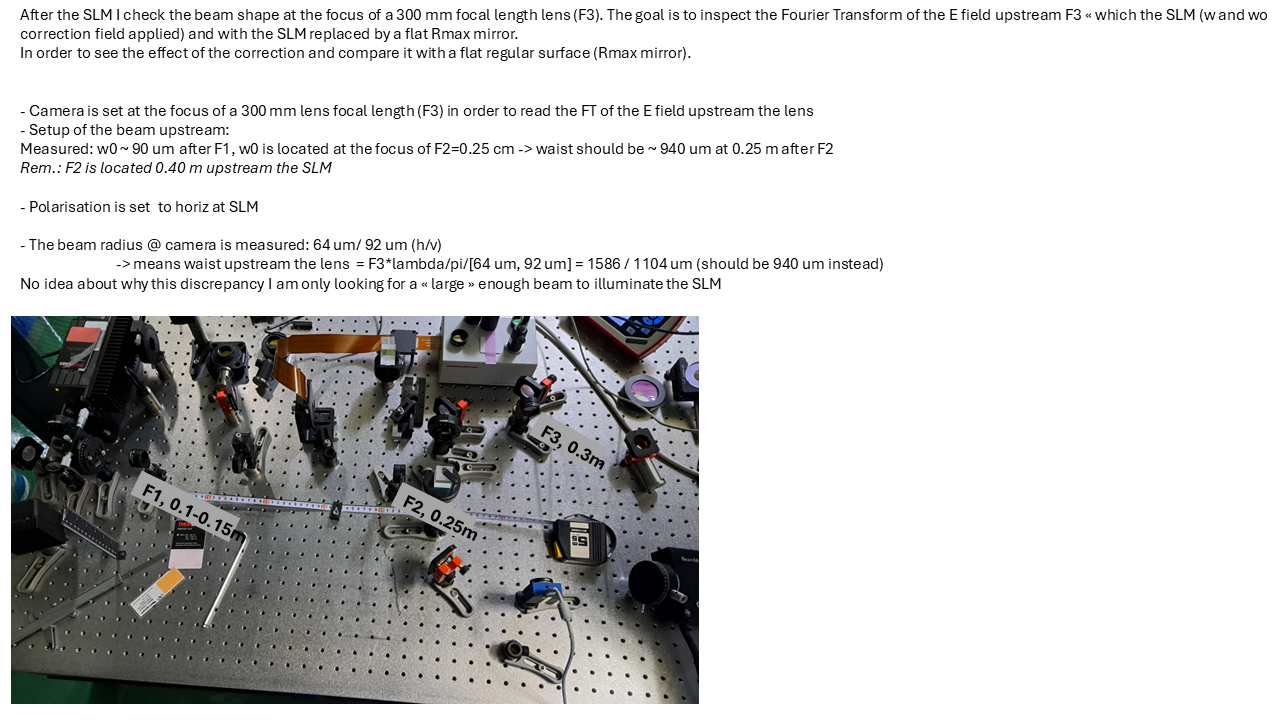
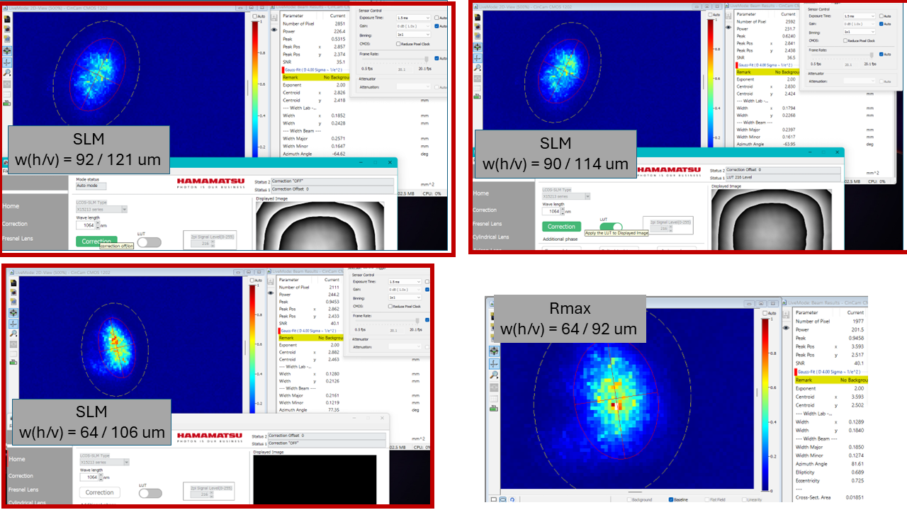
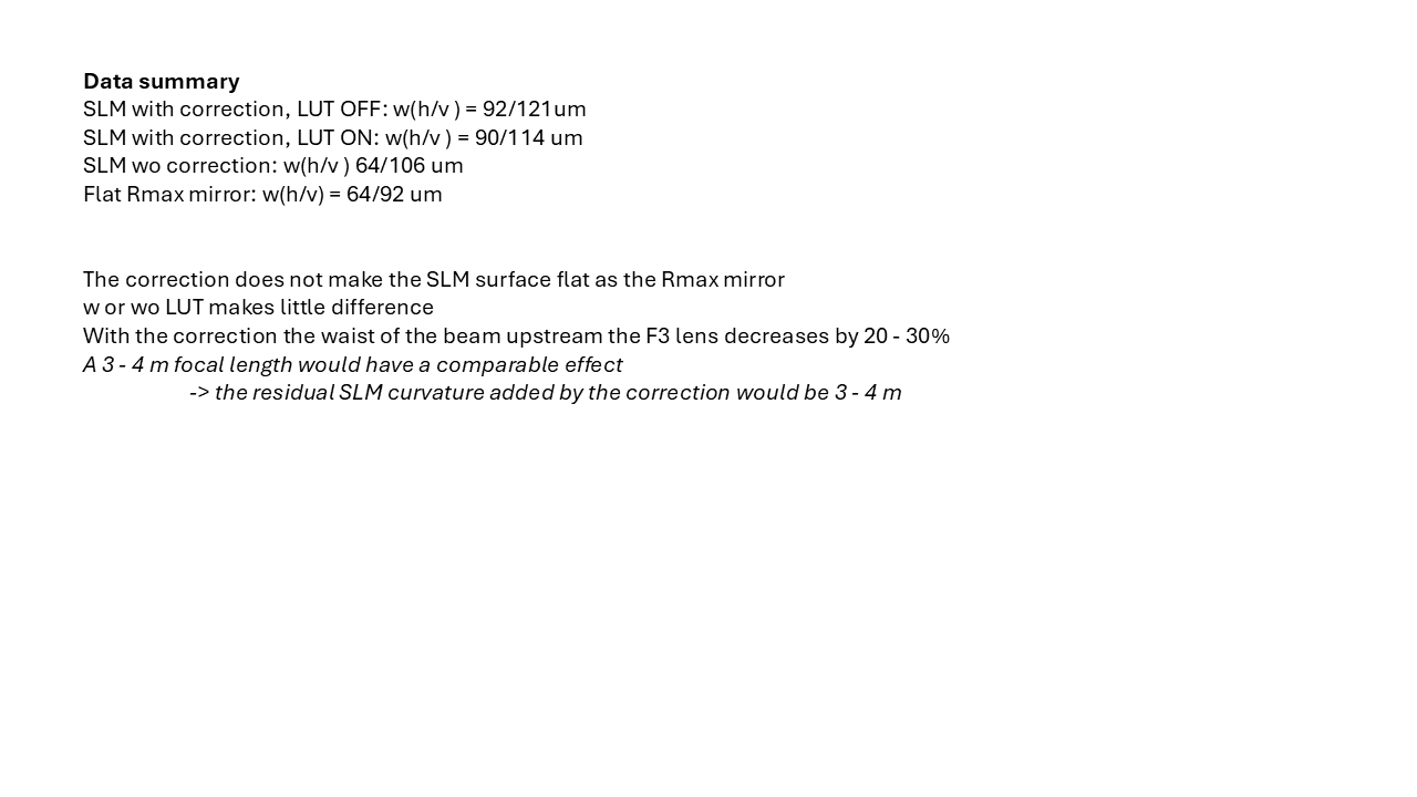
It seems the correction file does not compensate the SLM surface residual figure
See details in the attached slides
Feedback asked to Hamamatsu, wait for their reply
The labvew to take averaging and median was simplfied by directly using premade labview VIs for averaging, median, and errors.
The speed of reading data from polcam is 20ms. This is becasue the speed of polcam is 60fps. This brings us to 1/60 s= 20 ms. The labview can't read faster than this.
The saving of S1, S2, S3 from polcam, which were the stokes parameters, were removed.
The file will now save in the format:
scan , shift, azi, std azi, ell, std ell, polcam power, std polcam power, pm power, std pm power.
A new VI was made which is "Birefringence Map with camera_v2.vi".
[Marc, Michael M., Shalika]
The initial implementation of this feature was made by removing the waiting time of the vi.
It led to visible artifact during the motion of the sample.
It was restored to the usual 500ms and resolved the issue.
Somehow, the VI is now faster than before to acquire each point.
Note that the 'artifact' are not artifact but our real data.
The waiting time makes the VI to stop acquiring data.
A new power meter had to be installed to monitor power fluctuations during birefringence mesaurement in the PCI room.
There were several issues to integrate and read power using the power meter in labview.
1. First it seemed that the power meter driver was not present. So, we installed new drivers. But this didn't resolve the issue.
2. We thought the port of connection is not being recognized and so we tried changing the port definintion to IVI driver. Although, we could see the new port on NI max, we didn't resolve the issue.
3. The issue in reality was that the windows is 64bit but labview was 32bit. I uninstalled the thorlabs opm and installed again. The new VI to read was directly made from the thorlabs folder for power meter and not by the labview palette options. The error is resolved completely. You don't need to use 1 and 2, because the issue was due to labview not able to find the libraries in palette. The labview VIs in palette don't exist because of different version of windows and labview. When your issue is resolved, even though NI max won't recognize your power meter, it exists, and can be read, simply by using the port number like USB0::0x:1313::0x8078::P0048841::INSTR
To anyone who woould get into this issue
1. Check the versions of softwares installed. Most likely this is the issue. This was the case for everytime I encountered the issue during interfacing thorlabs measuring tools with labview
2. If the Issue is 1.
a. Don't use the VIs avaialble for the measuring tool in labview palette.
b. Use the VIs for the tool from something like "C:\Program Files (x86)\National Instruments\LabVIEW 2018\instr.lib\TLPM". Just go directly wheere the version was installed.
c. Don't try to fix the labview driver for the tool if you see the broken arrow. You will need to either ignore errors to resolve, or reinstall.
3. If the issue is not resolved using 3, your only hope is to use the suitable version of labview which is compatible with your windows.
[Marc, Michael M., Shalika]
Note for future operation of any of the VI is that now only the new added powermeter is recognized by the VI.
If the one in transmission of the sample is used, it takes priority over the new one (likely because it becomes the number '0' powermeter recognized by the pc).
For now the transmission powermeter is turned off.
[Marc, Michael Miller]
Had to change COM of Zaber from 6 to 7.
We installed the 2 blades on translation stage.
Vertical cut at : 310 80 20
Horizontal al cut at : 380 140 20
last mirror is at 175 mm from blade when the blade is at 20mm.
MAX DC = 0.25V
After realignment, we reached about 0.07deg AOI for both vertical and horizontal direction.
The beam size is about 0.9mm for both vertical and horizontal direction across the longitudinal range of the translation stage.
All measurements and analysis files are saved on the online MATLAB as we have some issues with MATLAB license. To be reinstalled.
[Marc, Michael M. , Shalika]
We removed the previous birefringence readout from the imaging unit which was using PBS and several optics installed on a small breadboard.
Instead, we now use Thorlabs polcam that was aligned to the input beam.
We tuned the input QWP/HWP to reach circular polarization, then installed and aligned a polarizer to inject pure linear polarization.
While testing the polarizer alignment vs rotation, the power control HWP was mistakenly rotated sending up to about 300mW to the polcam.
It disabled itself crashing the vi but could be somehow recovered after sometimes.
It seems that the camera is still able to properly read polarization (at least linear) as the read value corresponds to the expected polarizer rotation.
This issue arised because when 2 motorized rotator controller are connected to the pc, only one is detected... For safety, after recovering the appropriate input power, we disconnected the power controller HWP.
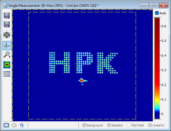
we setup the configuation for hologram display as decribed in the p 26 user manual, figure 21.
figure 1: camera CINOGY at the lens focus
-> The zero order residual seems to contain high power
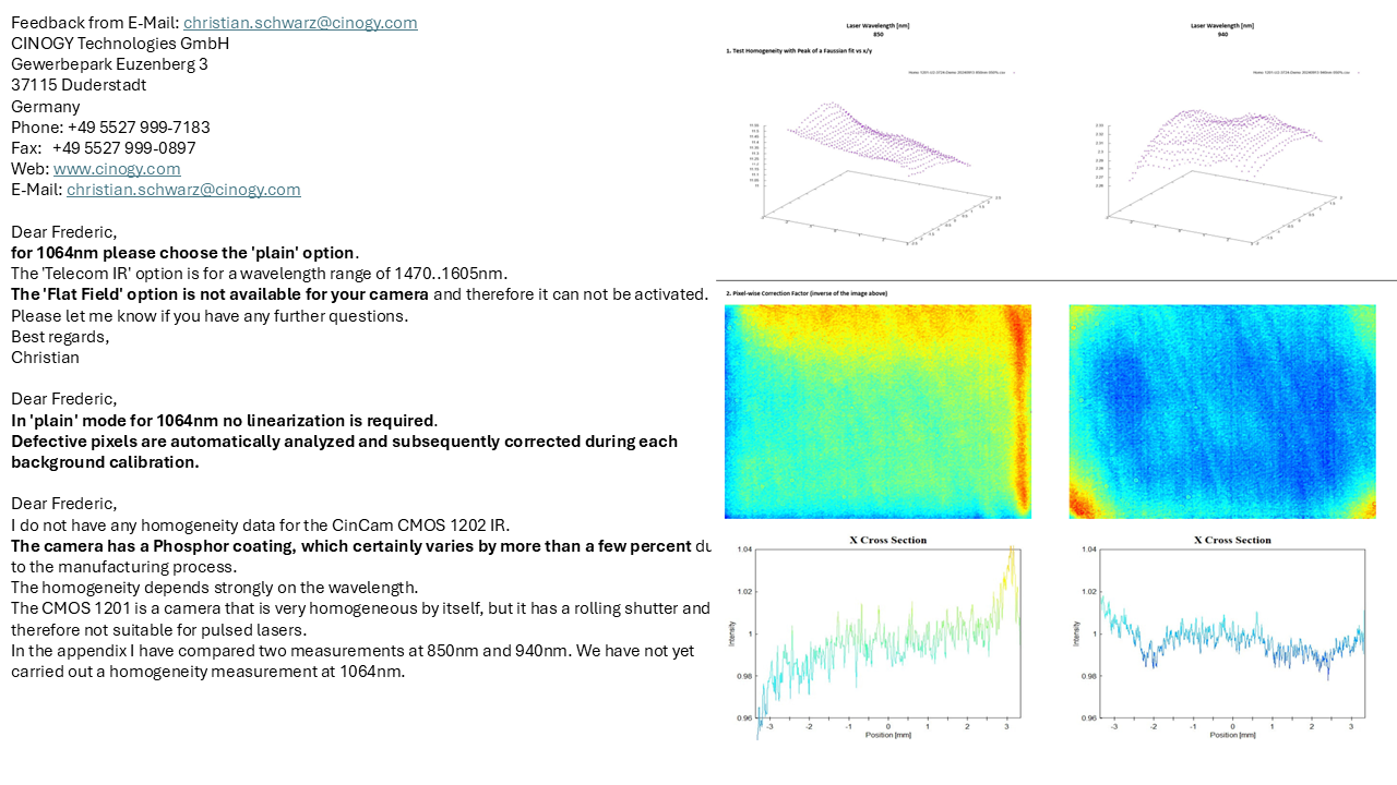
I got the feedback from Hamamatsu:
" ...I am Norihiro Fukuchi and sales engineer of LCOS-SLM.
There are several factors that cause the 0th order light to be generated, but it mainly depends on the diffraction efficiency characteristics of the LCOS-SLM.
Since it is difficult to eliminate the zero-order light, we can suggest ways to make it become low power density by Fresnel Lens Pattern (FLP).
The experiment results by superimposing FLP and CGH is shown on page 42 in software operation manual.
We can share the technical note of LCOS-SLM which shows characteristics details.
..."
See the attached technical

We use the 2nd lightwave laser, serie 126-1064-700, serial 225 (Nov. 1996).
The general datasheet (*) mentions waist (horiz/vertic) ~ 250/180 um at 5 cm from the laser front panel
(*) https://resource.lumentum.com/s3fs-public/technical-library-items/npro125126-ds-cl-ae.pdf?VersionId=null
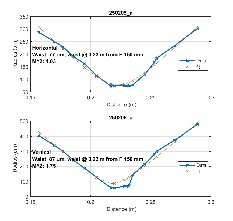
we check the beam profile after a 15 cm focal length lens (Thorlabs LA133-C) located @ 0.54 m from the laser front panel.
-> see figure 1, Weird behavior, M^2 ~ 1.75 along the vertical direction
we deduce the upstream waist (horiz/vertic) ~ 151/168 um at 0.1 m from the laser front panel.
Rem.:
- the beam at the output of the laser is quite shifted to the right (when looking to the laser) and let think it could be clipped by the shutter. However this is the vertical direction which features weird profile and the worst M^2 parameter. We found the same feature for the laser used by Shalika on EOM's experiment.
- figure 2, non-TEM00 feature at some distance from the waist
# Laser P vs I characterization for SLM experiment
Polarisation set to S (vertical)
I (A) P1(mW) P2 (mW)
1.38 3.69 97
1.50 6.18 168
1.60 9.7 280
1.70 14.5 380
1.80 18.2 480
2.0 28.8 764 (Rem_2)
P2: read at the laser output (after a L/2), meas. with the integrating sphere
P1: is after L/2 (Polar set to vertic), + BeamSampler (AOI ~ 25 deg) + Rmax + Lens
Rem_2: P1/P2 = 3.8% compatible with the Beam sampler R (R = 4.1% for 22 deg AOI and S polar)