NAOJ GW Elog Logbook 3.2

I made some changes to increase the speed of the vi
made a main project "Full_LC_control_project", which has temperature controller and LC control separate.
the LC control vi ofc can also access the temperature value
when you run, first run the temperature vi. then execute the dual step control
the speed is now 80Hz, you should be able to save data faster;
there is some artifacts that are seen in plots, its because of the some delays, that are added and also because of filling buffer first and then doing average. we don't do continuoous average. This can be resolved later. This doesn't affect the saved data.
The goal is to push one button and get all the maps done at once.
This implies moving both the sample in and out the laser beam to take maps and rotate HWP between every 2 maps.
A test sub vi to control HWP is available. Note that it is required to install and use the Kinesis 32bit for 64bit windows to bit compatible with our Labview and previous vi.
The library is saved in the Labview scripts folder of PCI.
I am now simplifying several vi by adding clustering. all new or modified vi are with cyan background colors.
There was some issue with powermeter but Shalika keen eye found it to be due to misnumbering of the cluster in the close vi.
white dot at top towards laser
# Shinkosha 16230472 (6/6)
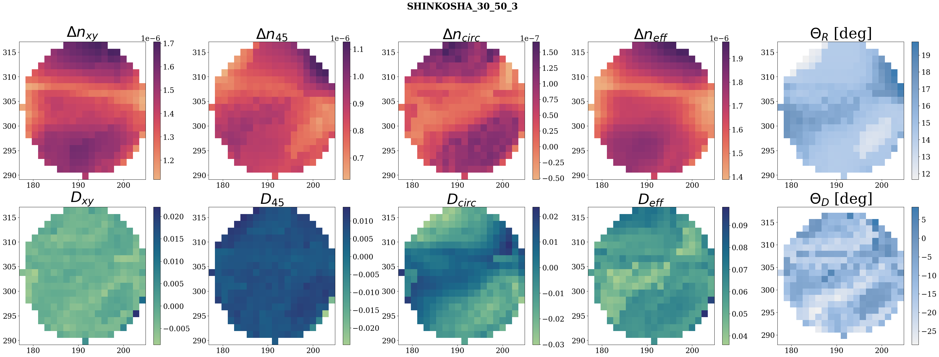
sample = 'SHINKOSHA_30_50_3'
thickness = 0.05
input_filenames = [
'Fri, Mar 14, 2025 9-54-31 PM.txt',
'Fri, Mar 14, 2025 10-06-52 PM.txt',
'Fri, Mar 14, 2025 10-48-41 PM.txt',
'Sat, Mar 15, 2025 12-02-03 AM.txt',
'Sat, Mar 15, 2025 12-27-39 AM.txt',
'Sat, Mar 15, 2025 12-53-41 AM.txt'
]
output_filenames = [
'Fri, Mar 14, 2025 9-41-59 PM.txt',
'Fri, Mar 14, 2025 10-20-20 PM.txt',
'Fri, Mar 14, 2025 11-41-05 PM.txt',
'Sat, Mar 15, 2025 12-15-09 AM.txt',
'Sat, Mar 15, 2025 12-41-39 AM.txt',
'Sat, Mar 15, 2025 1-05-32 AM.txt'
]

white dot at top towards laser
spike likely due to visible scratch on sample surface.
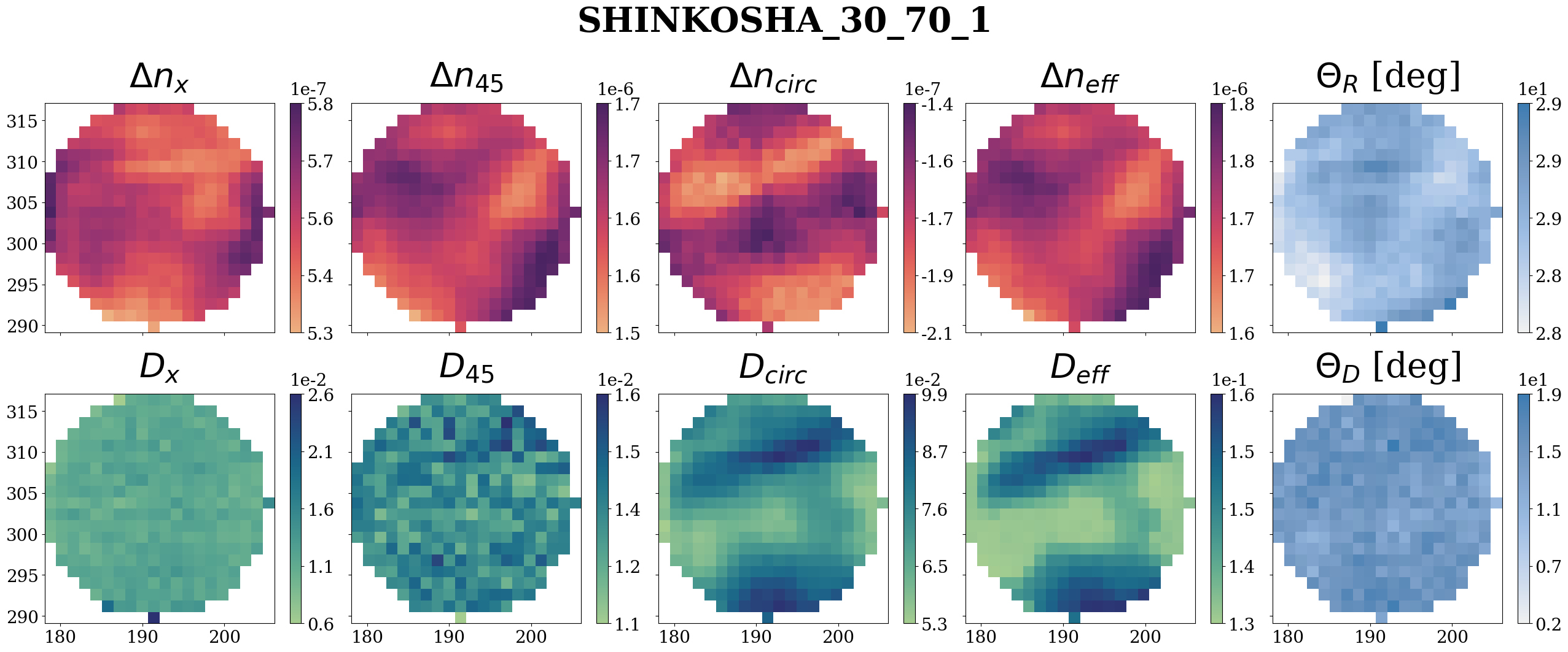
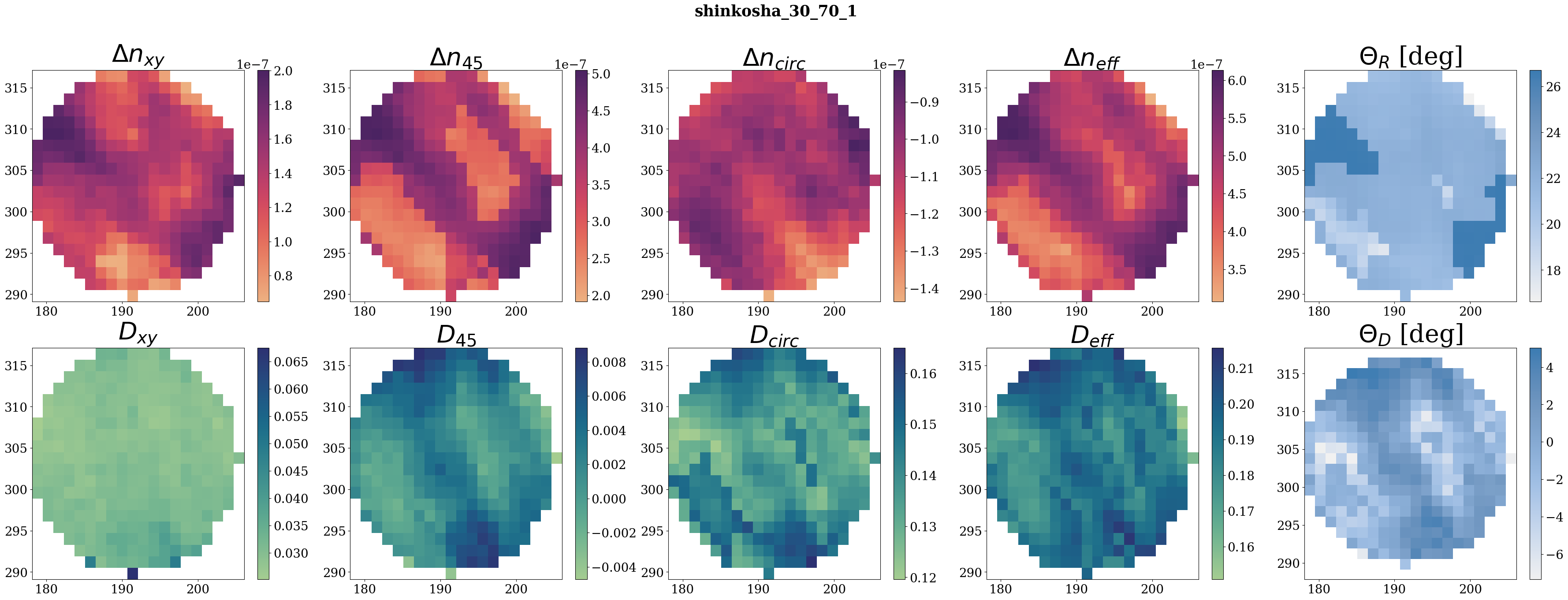
sample = 'shinkosha_30_70_1'
thickness = 0.07
input_filenames = [
'Mon, Mar 17, 2025 11-14-47 AM.txt',
'Mon, Mar 17, 2025 11-32-44 AM.txt',
'Mon, Mar 17, 2025 11-49-40 AM.txt',
'Mon, Mar 17, 2025 12-41-44 PM.txt',
'Mon, Mar 17, 2025 1-02-39 PM.txt',
'Mon, Mar 17, 2025 1-24-39 PM.txt'
]
output_filenames = [
'Mon, Mar 17, 2025 11-24-26 AM.txt',
'Mon, Mar 17, 2025 11-40-52 AM.txt',
'Mon, Mar 17, 2025 12-06-09 PM.txt',
'Mon, Mar 17, 2025 12-51-53 PM.txt',
'Mon, Mar 17, 2025 1-11-12 PM.txt',
'Mon, Mar 17, 2025 2-00-36 PM.txt'
];
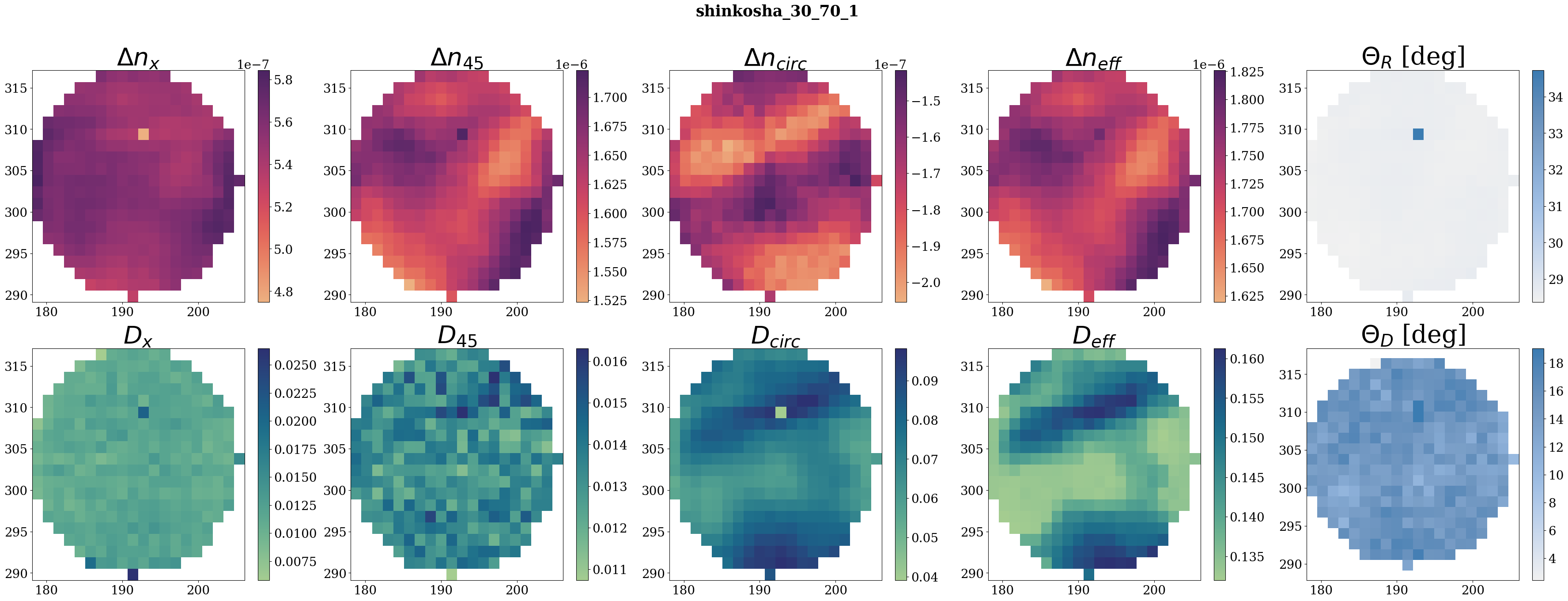
I had re-executed the code. I don't see the dot anymore.
I had increased the limitation on filtering by putting limits on (value + uncertainity), instead of having lower limit (value-uncertainity)
need to check the real shinkosha name
white dot at top towarsd laser
not fully sure about discontinuities... maybe from slight polarizer misalignment?
sample = 'shinkosha_30_70_2'
thickness = 0.07
input_filenames = [
'Mon, Mar 17, 2025 3-45-13 PM.txt',
'Mon, Mar 17, 2025 6-30-29 PM.txt',
'Mon, Mar 17, 2025 7-30-47 PM.txt',
'Mon, Mar 17, 2025 8-10-36 PM.txt',
'Mon, Mar 17, 2025 10-55-47 PM.txt',
'Tue, Mar 18, 2025 9-42-41 AM.txt'
]
output_filenames = [
'Mon, Mar 17, 2025 3-32-27 PM.txt',
'Mon, Mar 17, 2025 6-53-42 PM.txt',
'Mon, Mar 17, 2025 7-57-16 PM.txt',
'Mon, Mar 17, 2025 10-38-46 PM.txt',
'Mon, Mar 17, 2025 11-21-20 PM.txt',
'Tue, Mar 18, 2025 10-17-20 AM.txt'
]
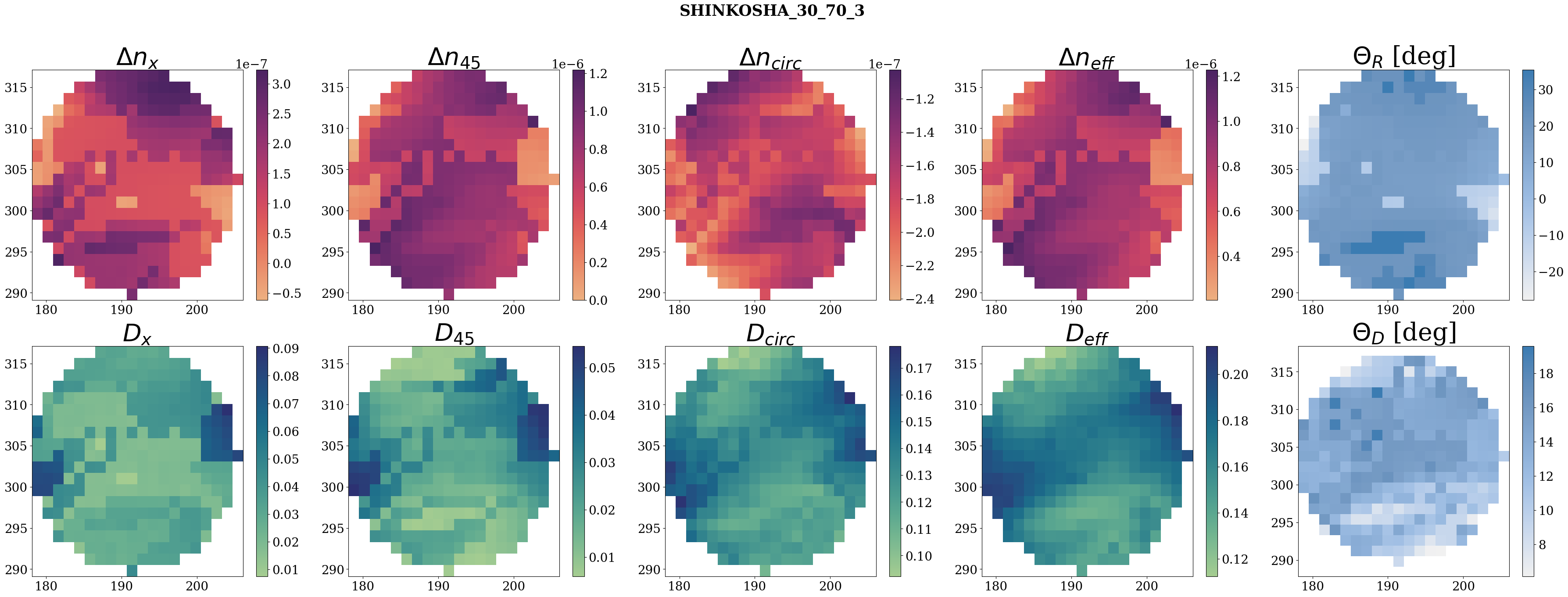
white dot at top towards laser
#3 (Shinkosha_30_70_3 1623046-3 (4/6)
sample = 'SHINKOSHA_30_70_3'
thickness = 0.07
input_filenames = [
'Tue, Mar 18, 2025 11-15-30 AM.txt',
'Tue, Mar 18, 2025 11-40-02 AM.txt',
'Tue, Mar 18, 2025 12-15-28 PM.txt',
'Tue, Mar 18, 2025 2-09-54 PM.txt',
'Tue, Mar 18, 2025 3-13-56 PM.txt',
'Tue, Mar 18, 2025 3-55-46 PM.txt'
]
output_filenames = [
'Tue, Mar 18, 2025 10-59-55 AM.txt',
'Tue, Mar 18, 2025 11-55-59 AM.txt',
'Tue, Mar 18, 2025 12-28-11 PM.txt',
'Tue, Mar 18, 2025 2-32-56 PM.txt',
'Tue, Mar 18, 2025 3-31-51 PM.txt',
'Tue, Mar 18, 2025 4-08-03 PM.txt'
]
The naming convention is : manufacturer_diameter[mm]_thickness[mm]_number
number is arbitrary.
thickness is in m to convert the retardation in delta n .
What is the unit of dimensions measured (for all the recent elogs)?
30 cm* 50 cm ?
thickness is 0.05cm?
Note that the 'artifact' are not artifact but our real data.
The waiting time makes the VI to stop acquiring data.
Is Arylamide same as acrylamide? -> yes it is the same, was a typo
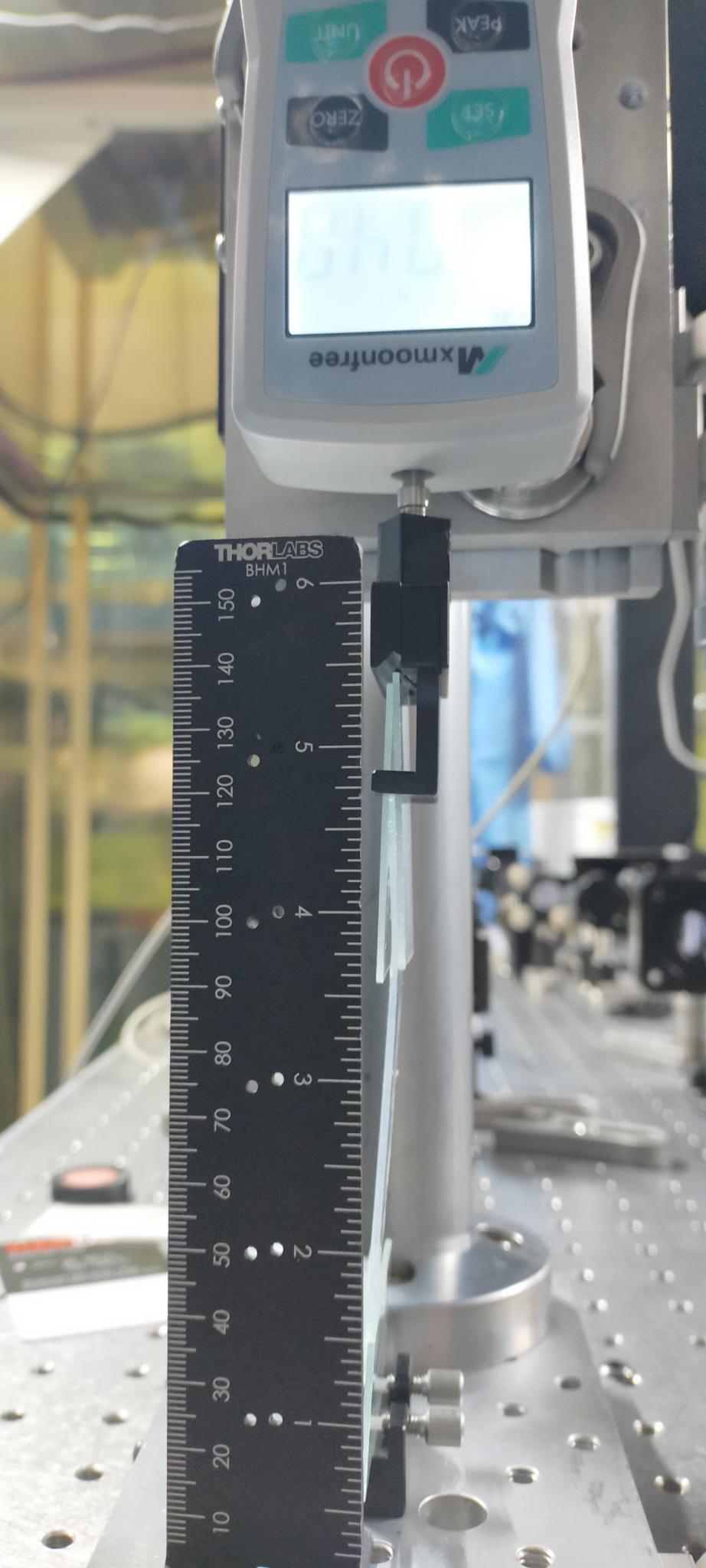
Note that for this measurement (and likely all previous ones) the hydrogel is tilted by a non negligeable amount as in Fig.1.
It should have an effect on all measurements (likely adding some offset at 0 force applied)
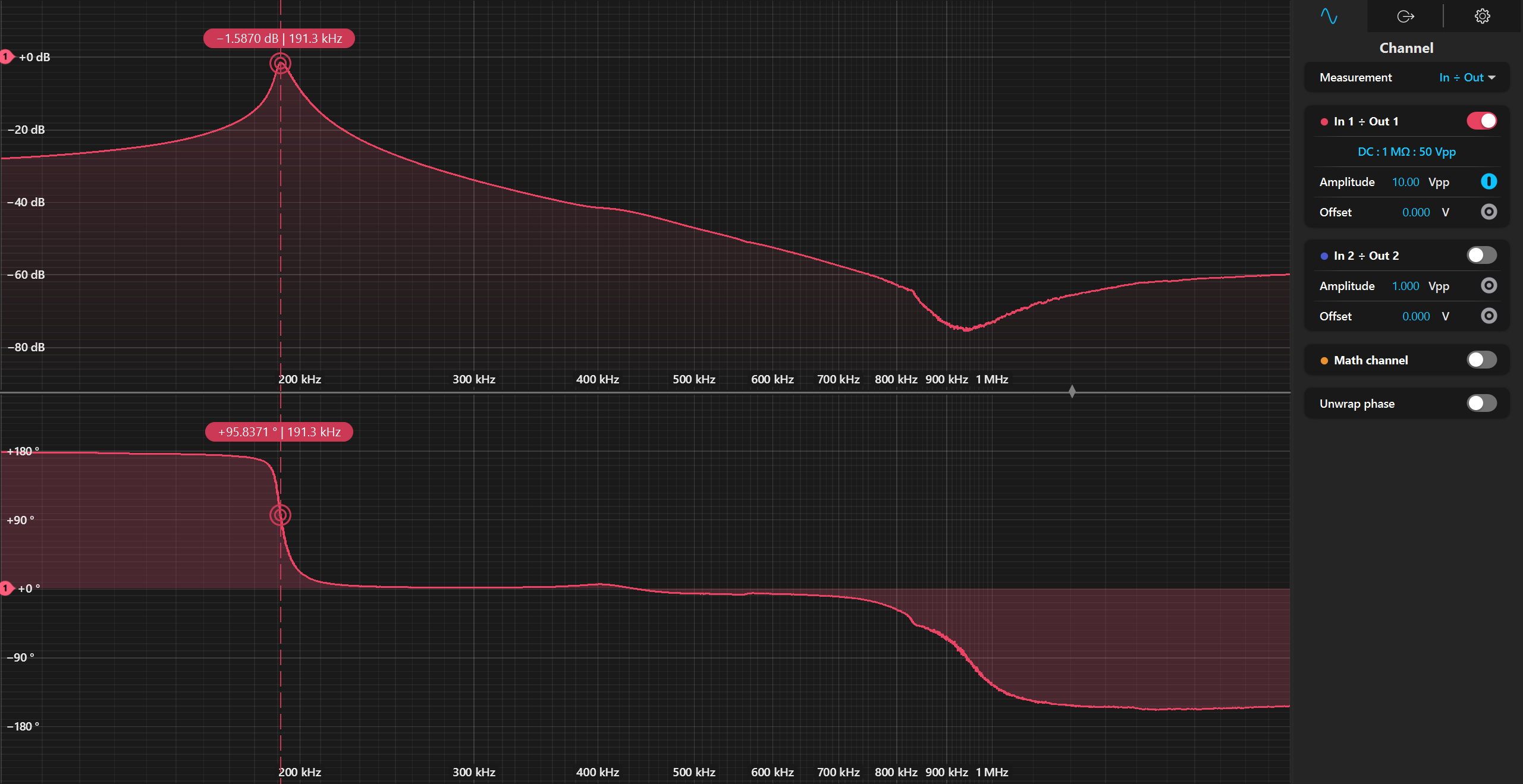
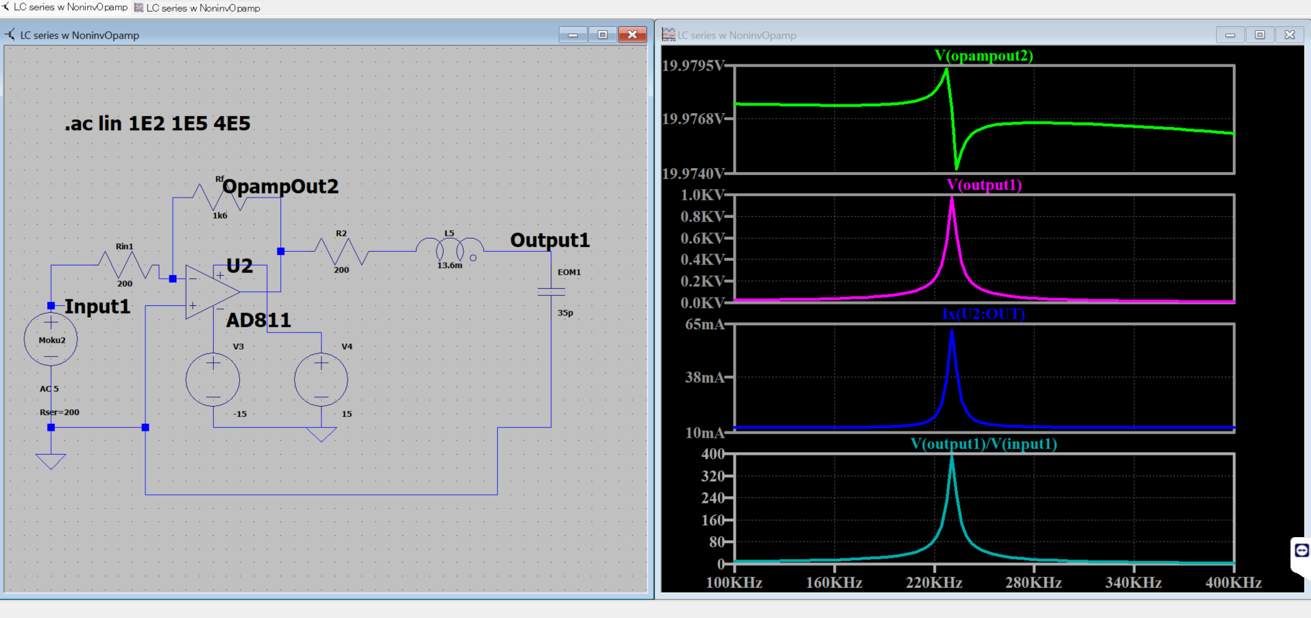
Now, I am using an Opamp EL2099CT, which has output current limit of 440mA. I made a inverting amplifier circuit (Fig 4). The spectrum was first observed with HV probe across the EOM, then by using the PD response with laser input across the EOM. There is impedance matching with moku using Rin=200ohm.
fig 1 : full TF using HV probe - 100:1 (no laser)
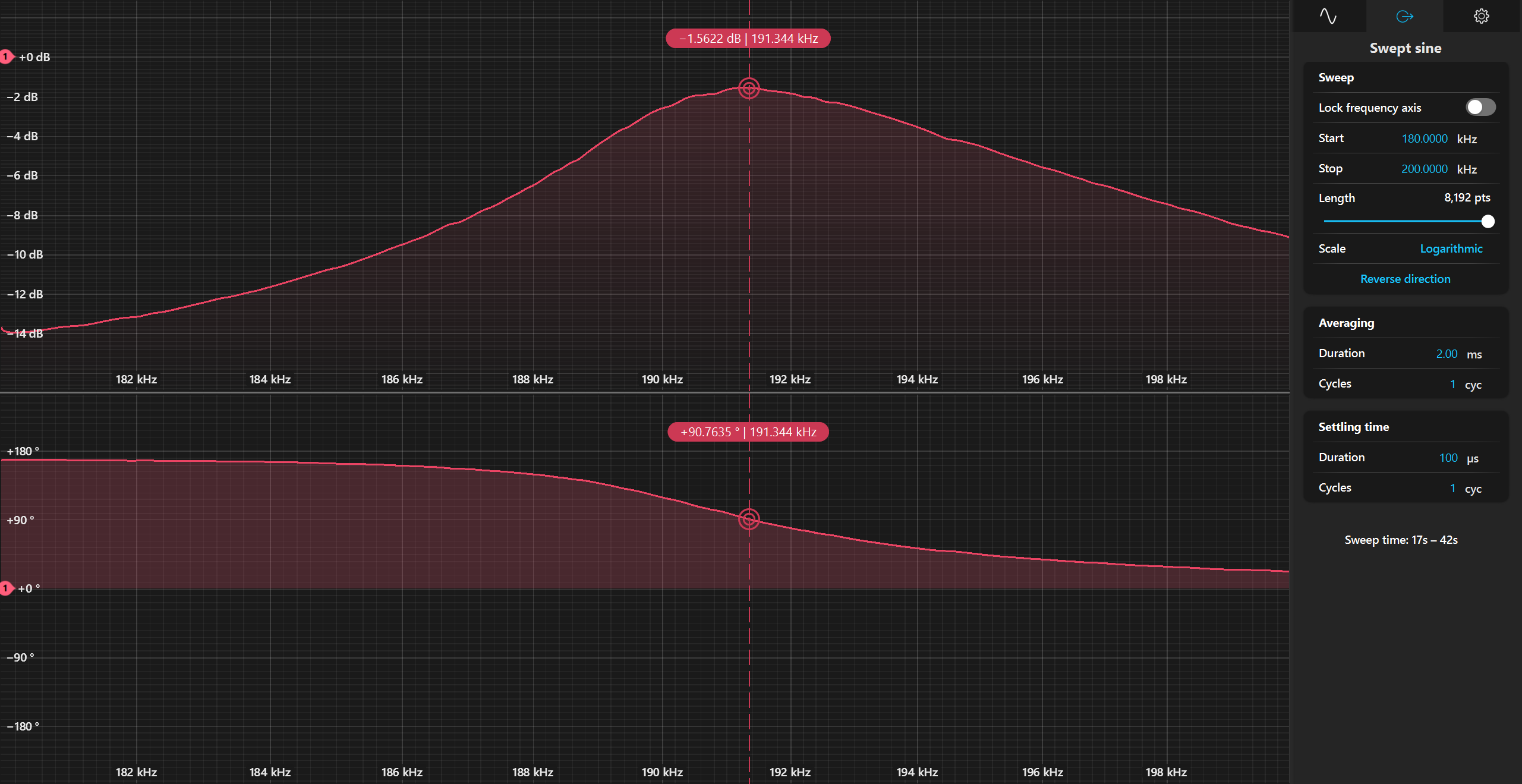
fig 2; zoomed of Fig 1
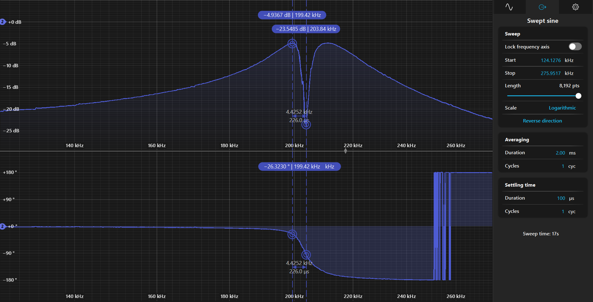
fig 3: TF measurement with laser (no HV probe)
Although the TF seems fine in Fig 1 and 2, there is something different in Fig 3. It could be the response of the PD.
I seem to have a gain of -1.5dB (with 100x probe)
so, 0.89*100 = 89 gain.
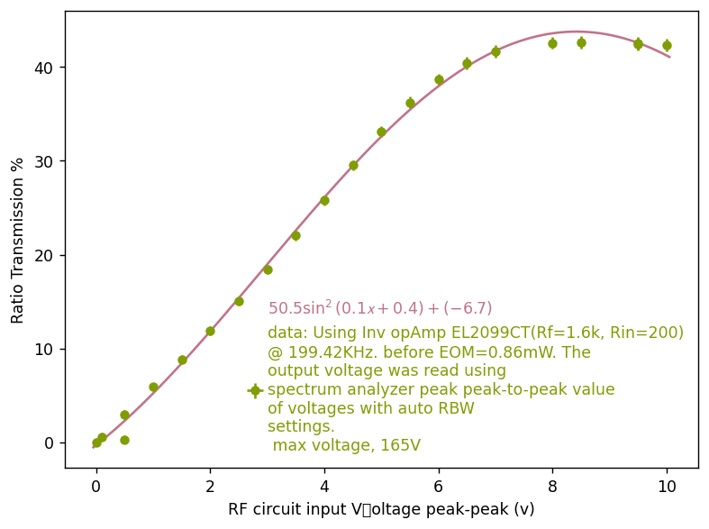
With 5V (amplitude), my circuit, should generate 89*5V= 445V , across EOM.
But, the response, seems saturated. See Fig 5. The rms voltage of the photodiode was converted to power.
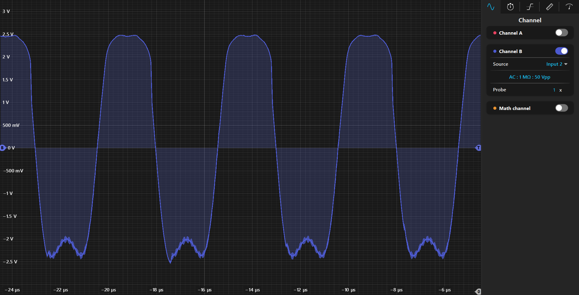
It was quite absurd that I still had saturation. See Fig 6 of photodiode response in oscilloscope.
Then, it occured to me, that the saturation has to do with limit of photodiode response itself. Since I am using a fixed gain photodiode, the maximum voltage it can read is 0-10V (for highZ), which means 10Vp-p. Since Moku input impedance is 1Mohm, it implies that I am limited by the photodiode response.
Next step:
Use a variable gain PD.
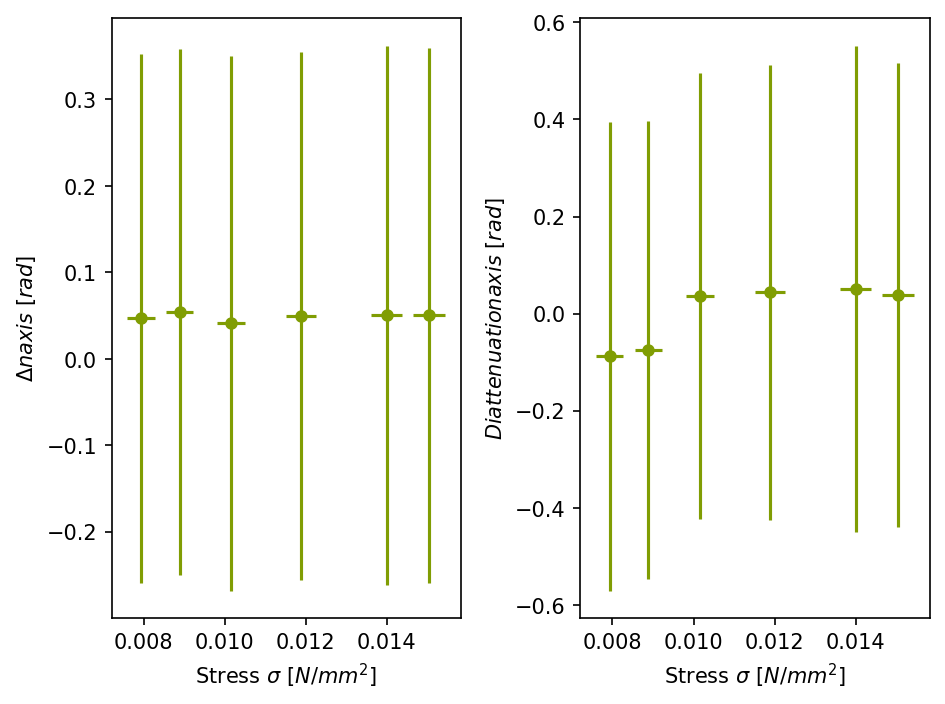
I have attached picture of the characteristics obtained of the materials. The figures are in the following order.
for Mix
Fig 1: Birefringence vs. Stress
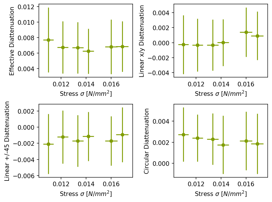
Fig 2: Diattenuation vs. Stress
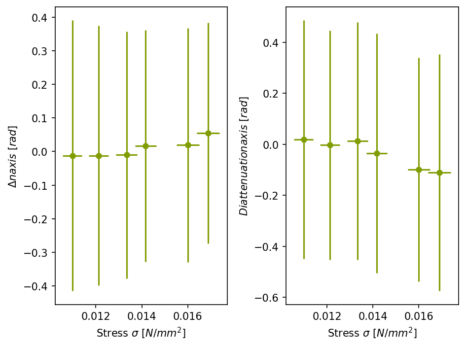
Fig 3 : Rotation vs. Stress
for Arylamide
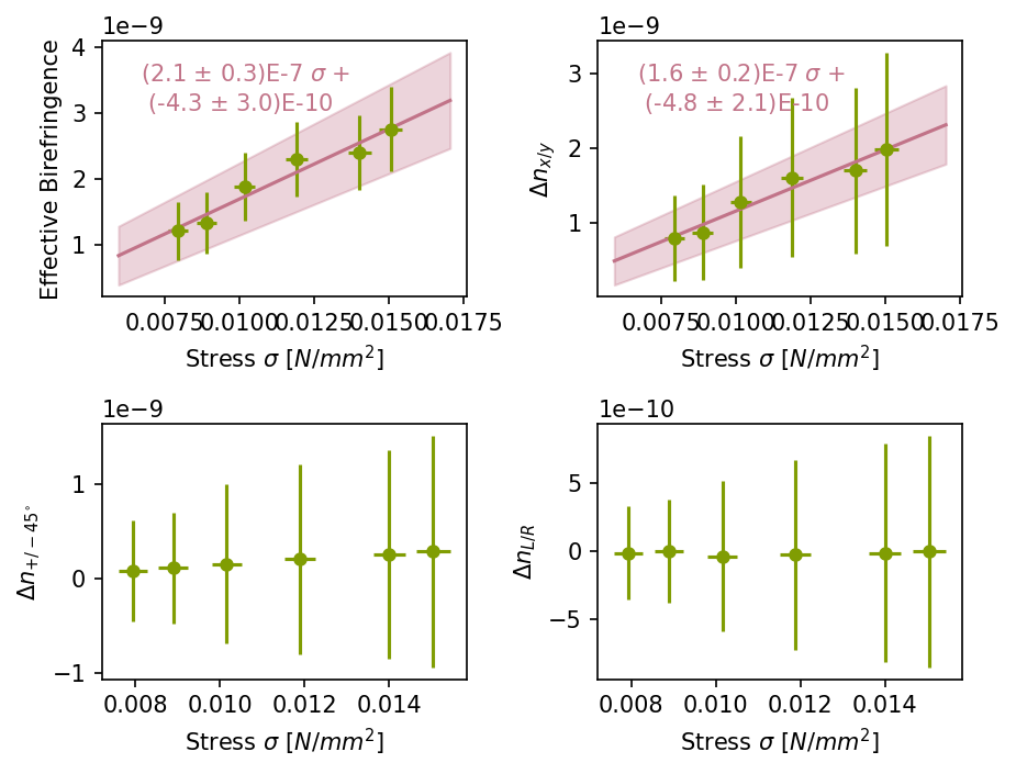
Fig4 : Birefringence vs. Stress
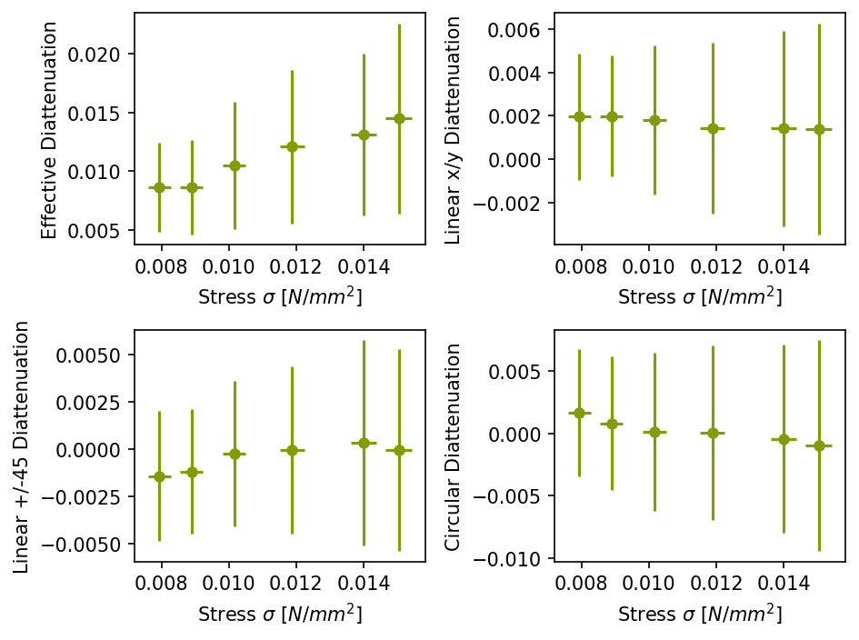
Fig 5 : Diattenuation vs. Stress
Fig 6 : Rotation vs. Stress
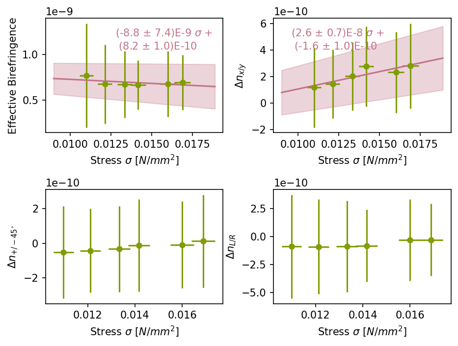
Is Arylamide same as acrylamide?
I have saved the first material characteristics in
C:\Users\atama\Dropbox\Cell Birefringence\Measurement data\hydrogel\Mix 1
the another one in
C:\Users\atana\Dropbox\Cell Birefringence\Measurement data\hydrogel\Arylamide 2
Since we are measurig Arylamide again, I have renamed the first measurement of Arylamide as 'Arylamide 1'
Edit 1:
Also the modifcations to the measurement are saved in
fixed_Fri, Mar 14, 2025 2-58-18 PM and fixed_Fri, Mar 14, 2025 1-56-26 PM
this sample was remeasured in the new configuration.
input_filenames = [
'Fri, Mar 14, 2025 9-54-31 PM.txt',
'Fri, Mar 14, 2025 10-06-52 PM.txt',
'Fri, Mar 14, 2025 10-48-41 PM.txt',
'Sat, Mar 15, 2025 12-02-03 AM.txt',
'Sat, Mar 15, 2025 12-27-39 AM.txt',
'Sat, Mar 15, 2025 12-53-41 AM.txt'
]
output_filenames = [
'Fri, Mar 14, 2025 9-41-59 PM.txt',
'Fri, Mar 14, 2025 10-20-20 PM.txt',
'Fri, Mar 14, 2025 11-41-05 PM.txt',
'Sat, Mar 15, 2025 12-15-09 AM.txt',
'Sat, Mar 15, 2025 12-41-39 AM.txt',
'Sat, Mar 15, 2025 1-05-32 AM.txt'
]
[Katsuki, Marc, Shalika]
Realigned beam and reinstalled powermeters and polcam.
mixed monomer (YY037:diphenyl+YY044:di-peg-phenyl) v/v=1/1 (ratio of monomer)
file : C:\Users\atama\Dropbox\Cell Birefringence\Measurement data\Fri, Mar 14, 2025 1-56-26 PM.txt
broke at 0.4. replace 160mm with 16mm. was mispelled.
input * C:\Users\atama\Dropbox\Cell Birefringence\Measurement data\Fri, Mar 14, 2025 2-49-38 PM.txt
another material
acrylamide(negative control)
C:\Users\atama\Dropbox\Cell Birefringence\Measurement data\Fri, Mar 14, 2025 2-58-18 PM.txt
seems measurement at 0.32 was actually 0.34N
0.4 N --> 0.42N
0.44 N --> 0.45 N
0.48 was not finished
Is Arylamide same as acrylamide?
I have saved the first material characteristics in
C:\Users\atama\Dropbox\Cell Birefringence\Measurement data\hydrogel\Mix 1
the another one in
C:\Users\atana\Dropbox\Cell Birefringence\Measurement data\hydrogel\Arylamide 2
Since we are measurig Arylamide again, I have renamed the first measurement of Arylamide as 'Arylamide 1'
Edit 1:
Also the modifcations to the measurement are saved in
fixed_Fri, Mar 14, 2025 2-58-18 PM and fixed_Fri, Mar 14, 2025 1-56-26 PM
I have attached picture of the characteristics obtained of the materials. The figures are in the following order.
for Mix
Fig 1: Birefringence vs. Stress
Fig 2: Diattenuation vs. Stress
Fig 3 : Rotation vs. Stress
for Arylamide
Fig4 : Birefringence vs. Stress
Fig 5 : Diattenuation vs. Stress
Fig 6 : Rotation vs. Stress
Is Arylamide same as acrylamide? -> yes it is the same, was a typo
Note that for this measurement (and likely all previous ones) the hydrogel is tilted by a non negligeable amount as in Fig.1.
It should have an effect on all measurements (likely adding some offset at 0 force applied)
move polarizer to increase the difference between the various polarization states.
motorized rotator swapped from HWP to polarizer
changed positions of 2 steering mirrors
had to change fork position of 1st lens on red path : RED ALIGNMENT TO BE CHECKED AGAIN BEFORE ABSORPTION MEASUREMENT !
horizontal cut at 360,115.5,20
vertical cut at 314.5, 200,60
blades at 20 is mm from last steering mirror 200mm
DC_max = 0.232V (from powermeter)
after vertical alignment : AOI = 0.006deg
z = [120, 70, 20];
filenames = {
'Fri, Mar 14, 2025 5-56-30 PM',
'Fri, Mar 14, 2025 5-59-03 PM',
'Fri, Mar 14, 2025 6-00-48 PM'};
after horizontal alignment : AOI = 0.06deg
z = [120,70,20];
filenames ={
'Fri, Mar 14, 2025 8-28-37 PM',
'Fri, Mar 14, 2025 8-31-20 PM',
'Fri, Mar 14, 2025 8-33-13 PM'};
Changed so that Image files Attached to comments also appear in the original thread.
Sample measured with input HWP rotation.
However, it seems that with the current situation only nearby polarization states can be generated that affects how many polarization states combination can be used (only 1 pair in below measurement).
sample = 'SHINKOSHA_30_50_3'
input_filenames = [
'Wed, Mar 12, 2025 12-00-10 PM.txt',
'Wed, Mar 12, 2025 12-14-14 PM.txt',
'Wed, Mar 12, 2025 1-18-31 PM.txt',
'Wed, Mar 12, 2025 4-39-58 PM.txt',
'Wed, Mar 12, 2025 4-45-39 PM.txt',
'Wed, Mar 12, 2025 4-59-45 PM.txt',
'Wed, Mar 12, 2025 5-05-32 PM.txt',
'Wed, Mar 12, 2025 5-19-36 PM.txt'
]
output_filenames = [
'Wed, Mar 12, 2025 12-06-17 PM.txt',
'Wed, Mar 12, 2025 12-18-40 PM.txt',
'Wed, Mar 12, 2025 1-24-16 PM.txt',
'Wed, Mar 12, 2025 4-35-22 PM.txt',
'Wed, Mar 12, 2025 4-50-50 PM.txt',
'Wed, Mar 12, 2025 4-55-12 PM.txt',
'Wed, Mar 12, 2025 5-10-00 PM.txt',
'Wed, Mar 12, 2025 5-14-37 PM.txt'
]
thickness = 0.05
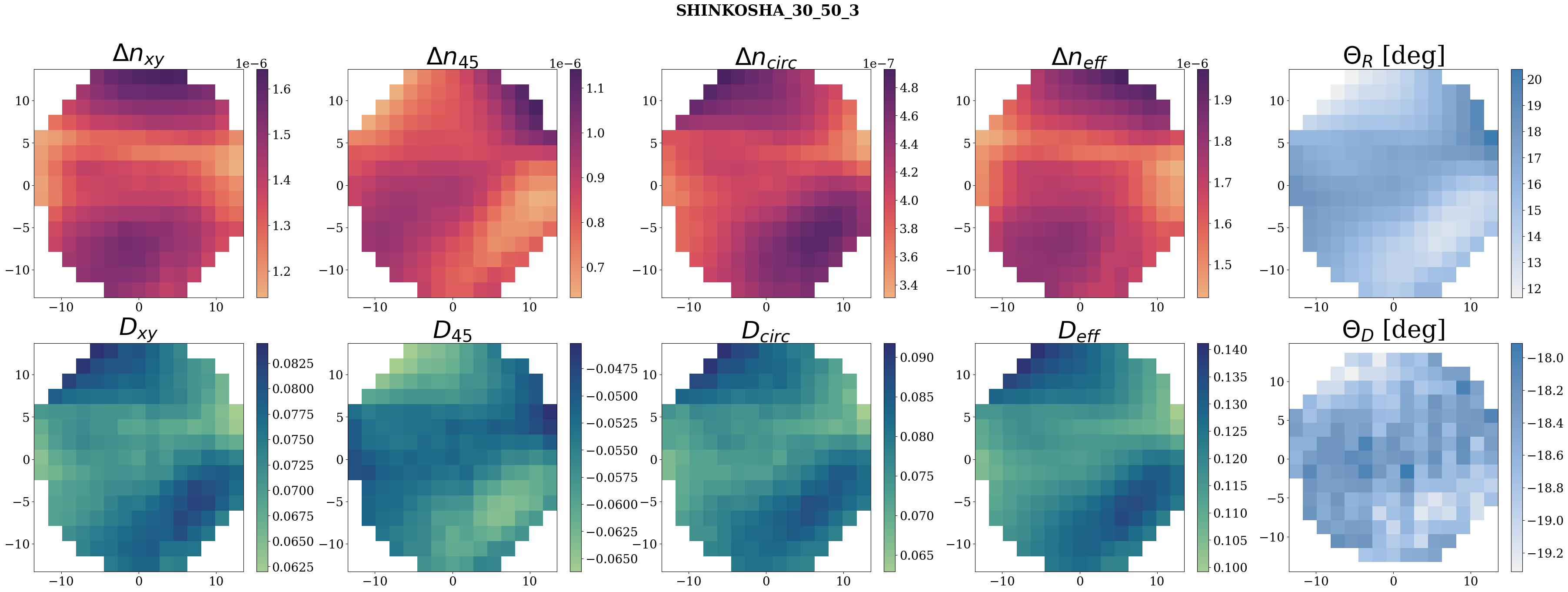
this sample was remeasured in the new configuration.
input_filenames = [
'Fri, Mar 14, 2025 9-54-31 PM.txt',
'Fri, Mar 14, 2025 10-06-52 PM.txt',
'Fri, Mar 14, 2025 10-48-41 PM.txt',
'Sat, Mar 15, 2025 12-02-03 AM.txt',
'Sat, Mar 15, 2025 12-27-39 AM.txt',
'Sat, Mar 15, 2025 12-53-41 AM.txt'
]
output_filenames = [
'Fri, Mar 14, 2025 9-41-59 PM.txt',
'Fri, Mar 14, 2025 10-20-20 PM.txt',
'Fri, Mar 14, 2025 11-41-05 PM.txt',
'Sat, Mar 15, 2025 12-15-09 AM.txt',
'Sat, Mar 15, 2025 12-41-39 AM.txt',
'Sat, Mar 15, 2025 1-05-32 AM.txt'
]
I restarted the squeezer electronics and did some checks. While turning on stuff in the FC room I clumsily dropped an oscilloscope on the floor. It still works but has some 45 kHz 4 mV noise when unplugged. Well it doesn't get used for critical measurements anyway so maybe ok. It has the yellow sticker "RM alignment feedback". I tested it using GRMC DEMOD (which was moved now to DDS2 DAC0) in both input channels and it gives basically the same result as the other oscilloscope.
SHG
The SHG was very misaligned, which was a bit strange considering that it usually maintains its alignment for quite a long time. It started out at about 40% mode matching. I used the steering mirrors and XY lens mount and realigned it to (1960 mV, 280 mV, 80 mV -> 84.5%), which is a little bit less than the reference alignment from 2024-12-25 (1840 mV, 200 mV, 140 mV -> 86.8%). I tried also the waveplate to correct the polarization but it had no effect. I also checked the input IR which reads 805 mW on the stick sensor vs 800 mW on 2024-12-25. I locked it and optimized the green output power to 296 mW (temperature controller 3.191) before the green FI.
GRMC
I checkced the GRMC alignment, it was ok, basically where I left it, so I didn't tweak it. I checked the error signal and optimized the demodulation phase to i-phase, then locked. I could see that it stably outputs 25.3 mW (316 mV on oscilloscope) of green power, checked at the OPO steering mirror 1 using the ring sensor, which is stable at the third decimal place on the power meter. I tweaked the servo gain to bring it to the threshold of oscillation (1.1) then reduced it (0.75). Also at one point the power meter randomly spiked to 44 mW, I'm not sure if this was due to the actual green power or just the power meter electronics being weird.
As presented in the research meeting there was an issue with GRMC unlock caused by the demodulation phase seemingly flipping from i-phase to q-phase. By switching channels to DDS2 DAC0, I can see that the problem is fixed. GRMC can maintain lock for > 90 min with the same output power and power stability (at least as seen on the power meter). In other words, the previously used channel DDS2 DAC2 is drifting in phase with respect to other channels. There is a bit of an annoying problem where when the GRMC/MZ assembly is manually unlocked it can sometimes kick one of the PZTs along the green path and requires the MZ to be realigned.
The PDH signal has about 100 mV DC offset as well which is a bit strange. But the error signal is 2.08 Vpk so it doesn't cause any immediately apparent problems.
IRMC
Mode matching was checked (1210 mV, 72 mV -> 94.4%) and was good. PDH signal is the same size as last time I checked (400 mVpk). I locked and saw it transmits 2.30 mV, same as normal.
Homodyne
Homodyne balance was quite bad, about -17 mV. I realigned it to zero, making sure to check the lenses in front of the homodyne PDs to confirm that there is no clipping of the beam. I checked the homodyne spectrum which gives the usual ~ -132 dBVrms/rtHz at high frequencies > 5 kHz. It seems to be about -131.8 dBVrms/rtHz at low frequencies, I feel it is maybe a bit noisy but I guess the squeezing measurement will determine the real performance.
to do: PLLs, OPO, nonlinear gain, squeezing