NAOJ GW Elog Logbook 3.2

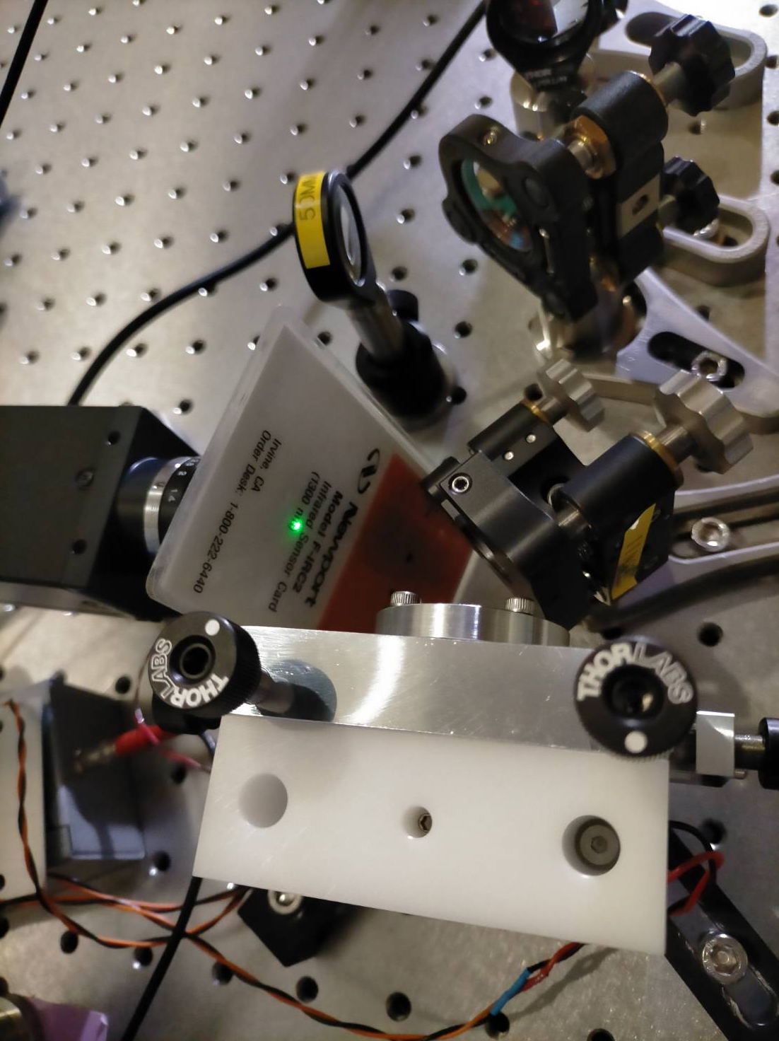
In order to measure scattering at 1064 nm, I borrowed the camera foreseen to replace the camera in transmission of the END mirror (bassler acA-2040-25gmNIR)
I found the camera but could not find its power supply nor its lens so I used the POE ethernet connection and a lens of a spare/broken (?) camera nearby the first target.
I connected it to the new dgs switch for the camera server + ethernet connection for the front end and data concentrator pc.
The camera got really hot so I checked the power delivery of the POE which seemed fine (2W provided below the 3.1 W limit).
To made this check I connected my laptop to the switch and tweaked a bit the switch password and IP address.
However, because my windows is in japanese I could not tune too much the requirement on 'jumbo packet' so we will have to finalize this with japanese people.
I set a static IP address for the camera and could see the camera image on pylon software.
However, it seems that the 1064nm efficiency is really low so I'm not sure how well we will be able to see scattering.
I will do this test when AZTEC #3 birefringence measurement is finished.
Yuhang and Michael
We set up the OPO in the reversed configuration (incoupler mirror on the side of detection power meter) and generated green from the OPO. Then, the OPO was locked, and we attempted to measure the generated green power as a function of crystal temperature to find the optimal phase matching working point.
However, we didn't get very much power. Looking over a range of thermistor resistances 5 - 7.5 kOhm, we expected to see a large peak of generated green power somewhere, but the most we got was 42 uW on the detection power meter (Yuhang thesis fig 4.26 shows 110 mW of green near 7.3 kOhm resistance and a smaller 83 mW peak near 6.7 kOhm). Before the measurement we removed some ND filters before the input FI, and early in the measurement we removed an unnecessary beam splitter in the laser path then realigned the OPO. But, it looks like the internal alignment is quite bad now, compared to 3006, probably just from removing those optics.
Yuhang and Michael
It was found that after flipping OPO, the alignment of OPO got worse and was hard to recover.
Today we checked again the alignment of OPO. We conclude that it is certainly that the flipping of OPO makes alignment worse. This is because that the mode matching condition is very much different depending on which side the laser enters OPO.
It was always questioned how we can make sure a good internal alignment. In fact, the alignment procedure of OPO is not so much different from our filter cavity. The only difference is that we cannot control the angle of OPO reflection surfaces as easily as the filter cavity mirrors.
For OPO input surface, we adjust injection beam to make injection and reflection overlap. But at the same time, we need to make sure the crystal transmission has a good shape.
For OPO end surface, we adjust input-coupler surface position to find interference.
At this step, the alignment is not optimized but we need to fix the input-coupler. Then we need to optimized mode matching. When optimizing mm, we need to pay attention to which lens is more sensitive. Pay attention also that after moving a lens, we basically just need to move the tilt of one steering mirror to recover alignment and compare the new mode matching HOM to understand if the mode matching is getting better or worse.
After optimizing mode matching, if there is still misalignment. (It was found that misalignment level is different when optimizing mode matching) We need to adjust input-coupling mirror.
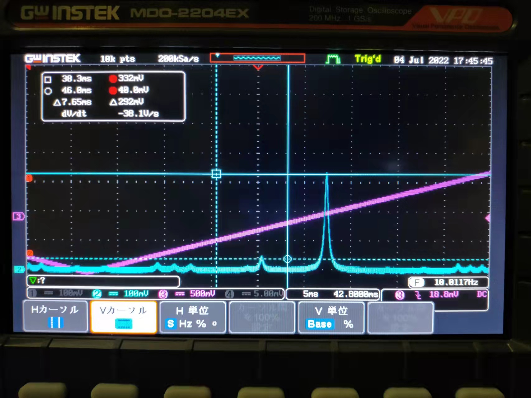
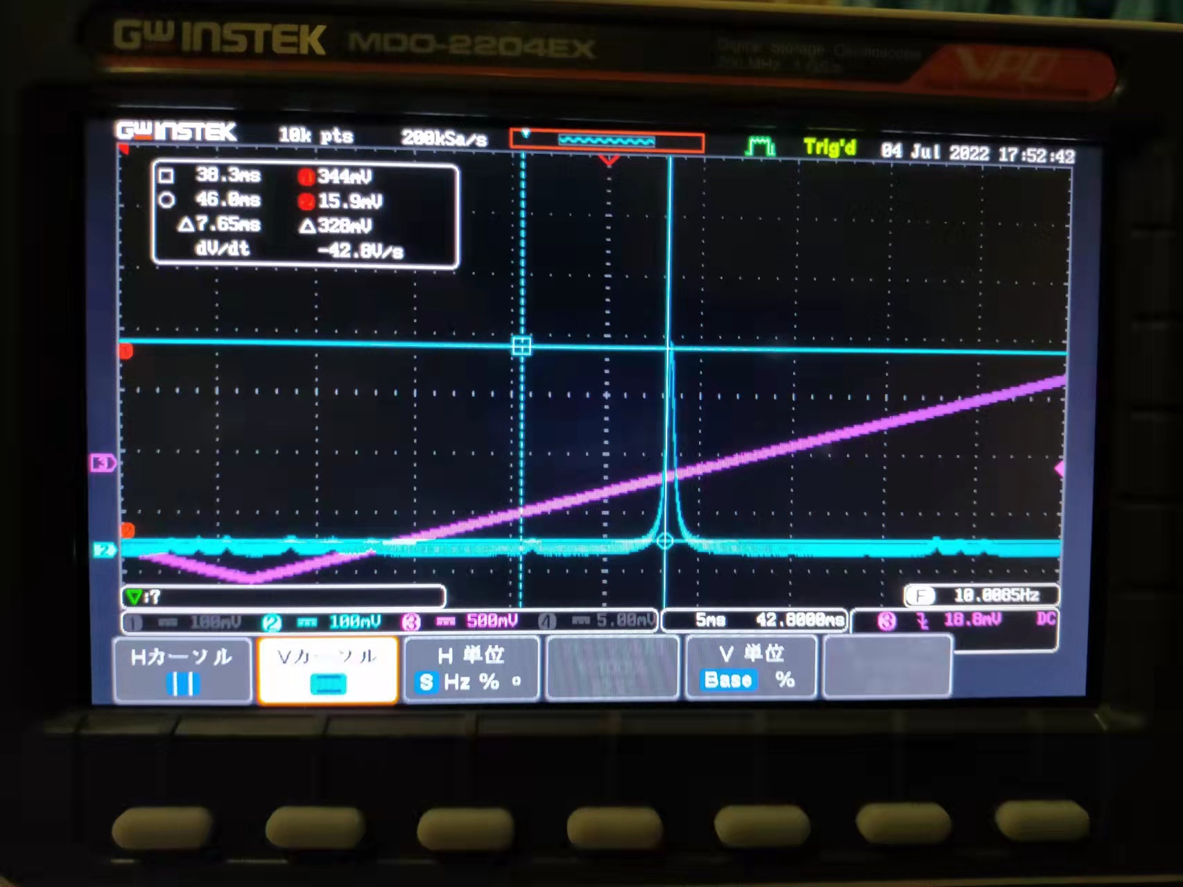
The attached two figures show two situations: 1. after optimizing mode matching, before final alignment of input coupling mirror 2. after final alignment of input coupling mirror
There is still space to further optimize OPO alignment. Note that the OPO transmission power is increased in Fig.2.
Yuhang and Michael
After the OPO alignment optimization, it was found that PDH signal was lost. Today, we found what is causing this problem: the OPO transmission PD is misaligned (drop from more than 5V to ~50mV). After aligning OPO transmission PD back, the PDH signal is recovered. (It was checked that the signal sent to EOM is 2Vrms, according to logbook2469, the modulation strength is 0.1-0.3rad/V, so we should have a modulation of 0.2-0.6rad. If we have 0.6rad, we should see about 10% power drop from carrier. If we have 0.2rad, the power goes to sidebands should be negligible. the modulation should be almost negligible since we didn't observe a power decrease after sending modulation)
Then we measured OPO generated green power as a function of OPO temperature. The measurement offset power on power meter is 3.3uW. We take measurement from temperature controller reading 7.7kOhm to 6.5kOhm with a step of 0.02kOhm.
These are the measurements results
| 7.700 | 7.680 | 7.659 | 7.640 | 7.620 | 7.601 | 7.579 | 7.560 | 7.540 | 7.519 | 7.500 | 7.480 | 7.459 | 7.440 | 7.420 | 7.400 | 7.380 | 7.361 | 7.339 | 7.320 | 7.299 | 7.280 | 7.260 | 7.240 | 7.220 | 7.200 | 7.179 | 7.160 | 7.140 | 7.119 | 7.099 | 7.080 | 7.059 | 7.040 | ||||||||||||||||||||||||||
| 93.0 | 93.4 | 94.0 | 94.3 | 94.5 | 94.6 | 94.6 | 93.8 | 94.2 | 93.7 | 94.6 | 96.0 | 97.7 | 99.8 | 102.2 | 105.3 | 109.0 | 112.5 | 116.8 | 120.5 | 122.8 | 123.0 | 120.0 | 114.5 | 106.9 | 99.0 | 92.5 | 87.0 | 81.7 | 77.6 | 73.0 | 68.7 | 65.0 | 62.6 |
However, during this measurement, we found that the OPO lock was having some issues due to the disturbance from temperature change while OPO kept locked.
Thus we performed again the measurements with a OPO unlock/lock between each measurement. This new measurement didn't have locking issue and will be reported later as a comment to this logbook.
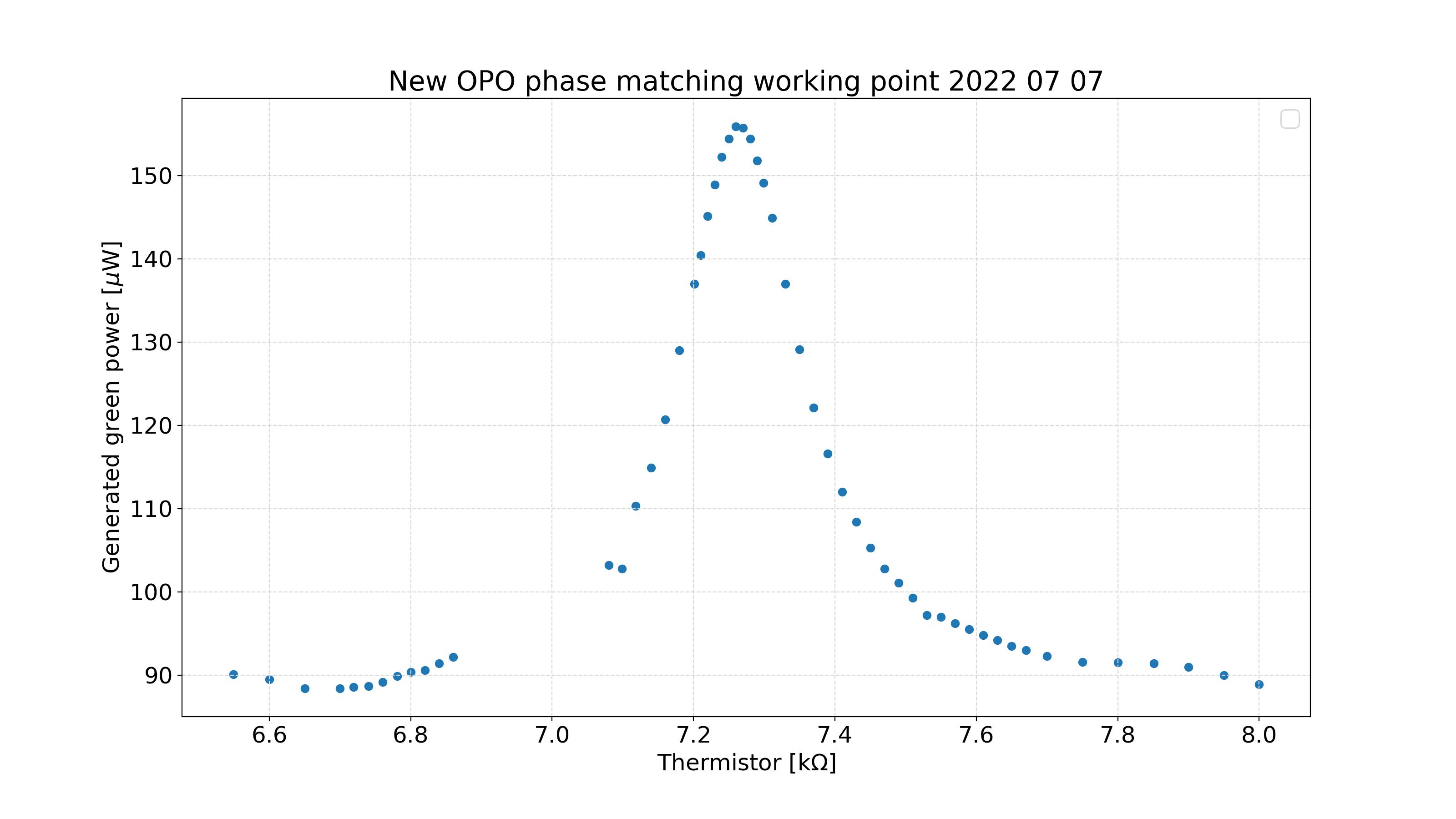
Here is a set of data points measured for generated green power versus thermistor resistance. The PDH lock was optimised at each temperature change. Note that only about 200 µW of infrared is sent to the OPO. The gap was just due to a note taking error, so we will fill out the rest of the points soon.
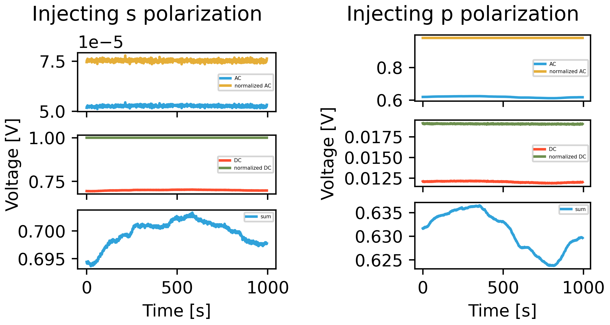
Previous analysis had some biased due to the calibration of our signals.The new calibration should take into account non ideal PBS and differents photodetectors.
We can express our 2 signals as :
DC = (Rs * Is + Rp * Ip ) * p(t) * Ks
AC = ( (1 - Rs) * Is + (1-Rp) * Ip ) * p(t) * Kp
where
Rs and Rp are PBS reflectivities for s and p polarizations
Ks and Kp are gain of the photodetector for respective s and p polarization readout
p(t) time-varying power fluctuations.
By measuring all these parameters, we can then reconstruct Is and Ip powers from our lockin amplifiers signal.
After carefully aligning the QWP and HWP to have linear s polarization, we measured AC and DC signals for 10 mn while injecting first s then p polarizations.
The measurements are attached in figure 1.
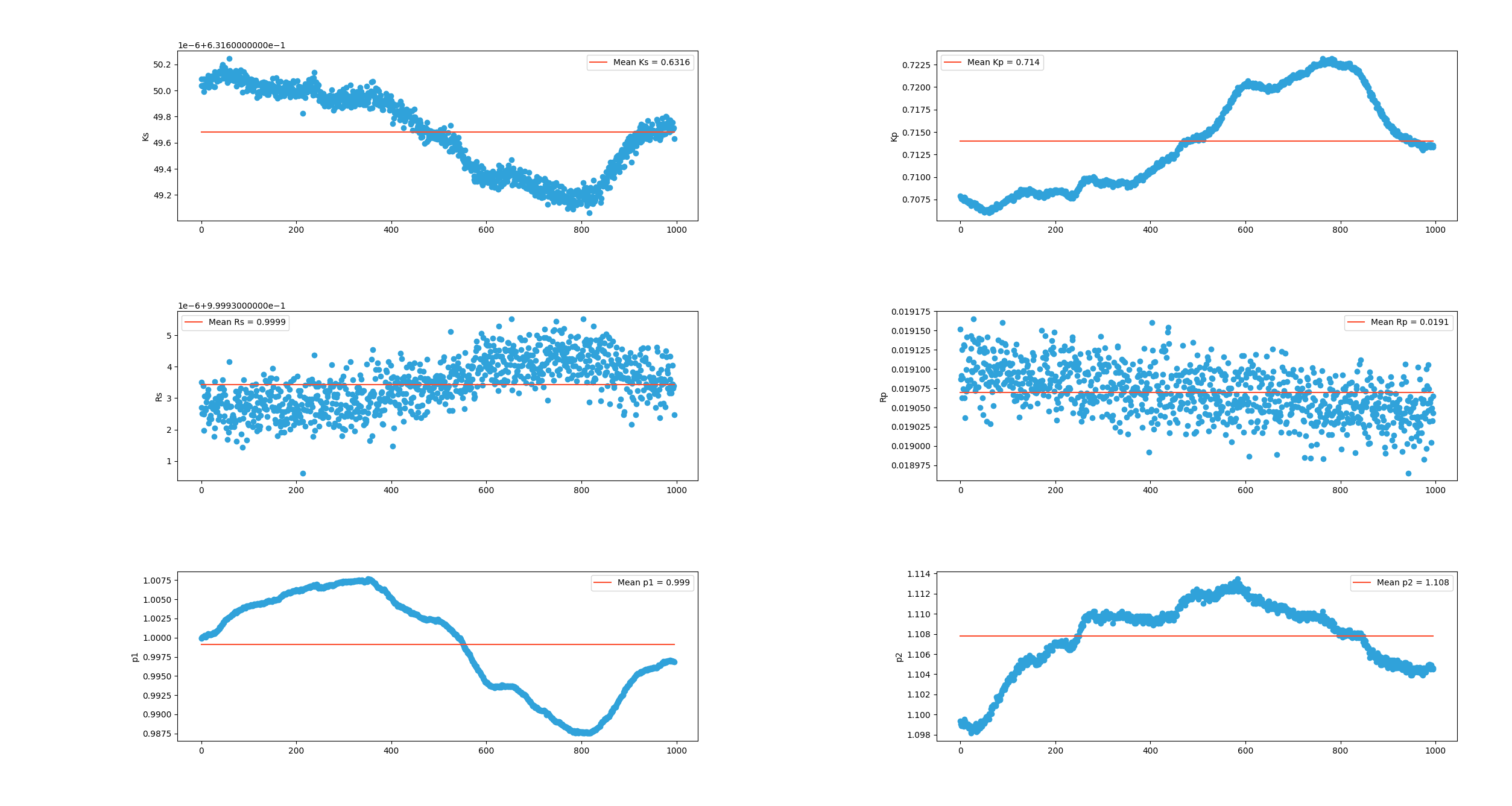
From these measurements, I could compute all the coefficients as shown in figure 2.
Note that here p1 are power fluctuations while injecting s polarization and p2 the one when injecting p polarization.
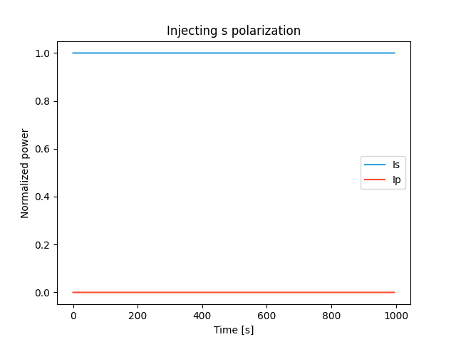
Using the mean of each of these coefficients, I show in figure 3 Is and Ip, the respective s and p polarizations when injecting s polarization.
As expected, Is = 1 and Ip = 0 and are independent on power fluctuations as well.
Rs and Rp coefficients are compatible with their specifications.
Also, during this calibration we found that the old lockin amplifier readout seems noisier than the new one.
Especially, we could barely see the power fluctuations that were hidden inside the noise (at that time we had about 2 nW of power reaching the photodetector but still a factor 50 above dark noise)
Following this calibration we started the AZTEC #3 birefringence measurement.
Yuhang and Michael
We realigned the new OPO in ATC yesterday. The screws holding OPO input-coupling mirror are adjusted to maximize the alignment. After this adjustment, the first higher order modes are totally removed. This indicates that the OPO internal alignment is finally optimized.
The second order mode is still very high, but it looks to be a Lagurre mode. So this should be optimized by a better mode matching. It was checked that this mode is not a wrong polarization.
In ATC, we have a temperature controller. We can start to look for the best temperature for green production. In addition, when green beam can be found, we should also characterize its beam profile.
[Aritomi, Yuhang, Michael]
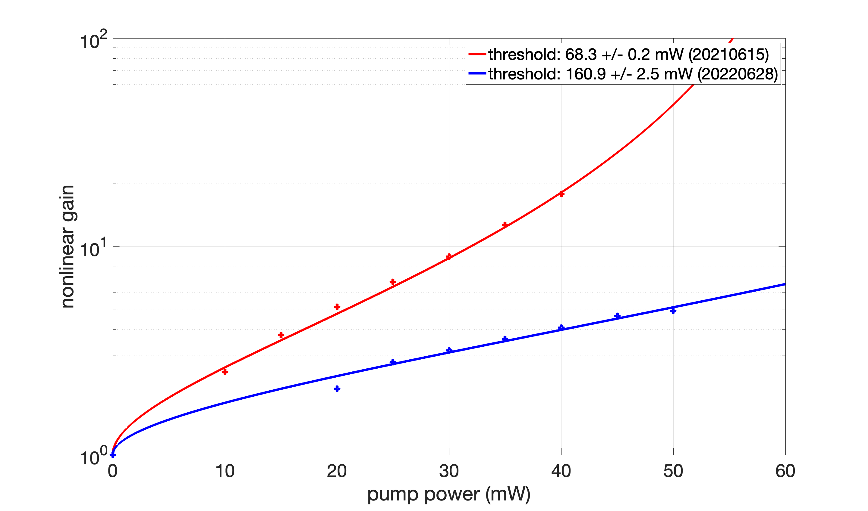
To investigate the issue of low nonlinear gain, we measured nonlinear gain with different green power as shown in the attached figure. The current OPO threshold is 161 mW which is much larger than last year in elog2577. We optimized PD position for BAB transmission and GRMC alignment, but the nonlinear gain is still low.
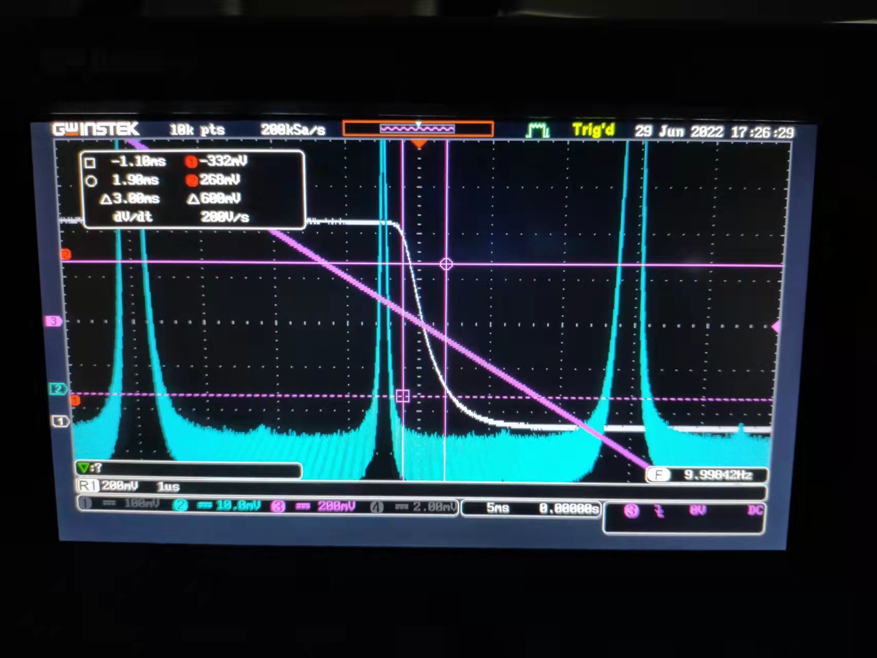
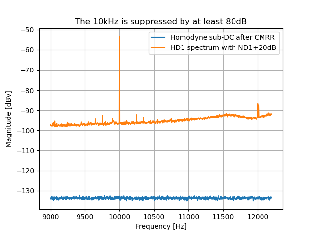
The CMRR was characterized by sending 10kHz 500mVpk-pk noise to laser intensity. To get the CMRR value, we compared two situation. One is when the LO is sent to only one eye of homodyne, but ND1 was used to make sure no saturation. Therefore, if the ND1 is removed, the noise should be increased by 20dB. The other situation is as usual way to measure shot noise, which is to measure sub-DC spectrum. The result is shown in Fig.1.
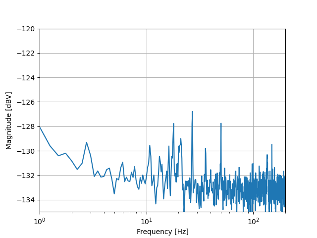
Then we also took a shot noise measurement at low frequency. The shot noise becomes flat until 3Hz (Fig.2). This is reasonable considering that the LO RIN measured in logbook 2988 shows almost 40dB RIN increase from 20Hz to 1Hz. Although we didn't have a clear number of CMRR in the past, we know that we achieved flat shot noise until 10Hz. Compared with the old usual shot noise, we should need more than additional 40dB CMRR to achieve shot noise like Fig.2.
Personal note: the 80dB CMRR is actually limited by the noise we can send to main laser intensity. Remind that the intensity noise modulation channel has an efficiency of 0.1A/V. So when we send 0.5V, we are actually modulating by only 0.05A the laser current. I think we can at least increase this noise by a factor of 10. But I checked the manual of our laser and I haven't found what is the damage threshold for this channel. This needs to be confirmed.
Abe, Marc, Yuhang
cleaning
We removed #4 from translation stage.
We inspected the optics with strong flashlight and green lights and the 'clean room' is now really dirty...
We decided to clean #3 before birefringence measurement (first surface cleaned and second should be dry tomorrow morning).
After the scattering measurement of #1, we applied first contact on one surface and will apply it on the second surface tomorrow before moving it to ATC for the TWE measurements.
measurement preparation
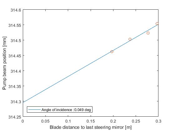
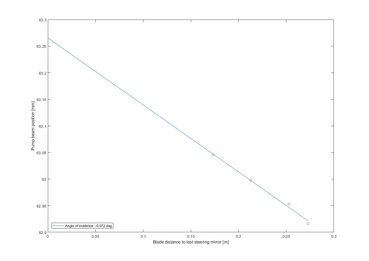
We installed the 2 razor blades on the translation stage and measured their position wrt to the last steering mirror on the injection bench (153 mm for vertical and 177 mm for horizontal).
We wanted to measure the beam position with laser diode current of 6 A and rotating the HWP to reduce the power but the beam shape became terrible (kind of 2 blobs)
We decreased the laser diode current to 1A and rotated the HWP to recover the same power as before.
The beam shape became reasonable again which means that we can proceed with briefringence measurements but need some investigation before being able to start absorption measurements.
We measured the beam position on the last steering mirror and tweaked the pitch/yaw of this mirror to have 0.049 deg AOI in vertical and -0.072 deg AOI in horizontal (see attached figures).
Tomorrow we will do calibration and start birefringence measurements.
I found an old elog420 which also says that BS Y picomotor doesn't work.
[Aritomi, Yuhang]
We checked the nonlinear gain with 25mW green (MZ offset: 4.2), but it is only ~2. It was 6.8 one year ago in elog2577. We optimized green alignment to OPO, OPO temperature, and p pol PLL frequency, but the nonlinear gain is still around 2. Here is the summary of today's measurement.
| green power (mW) | 0 | 25 | 25 | 25 | 25 |
| OPO temperature (kOhm) | 7.166 | 7.166 | 7.156 | 7.146 | 7.136 |
| p pol PLL (MHz) | 295 | 255 | 235 | 220 | 200 |
| BAB maximum (mV) | 98.4 | 216 | 226 | 230 | 232 |
| Nonlinear gain | 1 | 2.2 | 2.3 | 2.3 | 2.4 |
Yuhang, Aritomi
1. We tried to send 500mVpk-pk sine wave to main laser intensity modulation channel. It was not clear how much is the bandwidth for this channel. We will check this next time. In any case, the frequency was set as 10kHz.
2. We put ND1+ND0.5 filter for LO before homodyne. The voltage measured on the homodyne first eye is 220mV. We measured LO spectrum on homodyne eye one as H1ND2.txt.
3. We removed one ND0.5 filter. The voltage measured on the homodyne first eye is 659mV. We measured LO spectrum as well, named as H1ND1.txt.
4. We send 800Hz 700mVpp to IRMC locking servo noise injection point. And optimize noise subtraction manually.
5. We put back 500mV noise to laser intensity, then measure homodyne sub-DC spectrum as LONOI.txt. In this condition, no ND filter was used.
6. We measured LO sub-DC spectrum as LO0NOI.txt when there is no noise sent.
7. We measured homodyne sub-DC in this situation (from ~0.1Hz to 200Hz) (a temporary check indicates that it is about 70dB at least. We will inject more noise next time to see if we can achieve better CMRR.)
The CMRR was characterized by sending 10kHz 500mVpk-pk noise to laser intensity. To get the CMRR value, we compared two situation. One is when the LO is sent to only one eye of homodyne, but ND1 was used to make sure no saturation. Therefore, if the ND1 is removed, the noise should be increased by 20dB. The other situation is as usual way to measure shot noise, which is to measure sub-DC spectrum. The result is shown in Fig.1.
Then we also took a shot noise measurement at low frequency. The shot noise becomes flat until 3Hz (Fig.2). This is reasonable considering that the LO RIN measured in logbook 2988 shows almost 40dB RIN increase from 20Hz to 1Hz. Although we didn't have a clear number of CMRR in the past, we know that we achieved flat shot noise until 10Hz. Compared with the old usual shot noise, we should need more than additional 40dB CMRR to achieve shot noise like Fig.2.
Personal note: the 80dB CMRR is actually limited by the noise we can send to main laser intensity. Remind that the intensity noise modulation channel has an efficiency of 0.1A/V. So when we send 0.5V, we are actually modulating by only 0.05A the laser current. I think we can at least increase this noise by a factor of 10. But I checked the manual of our laser and I haven't found what is the damage threshold for this channel. This needs to be confirmed.
We try to measure the laser power using power meter.
We find that laser power is too low comparing spec sheet.
We use laser diode "L520P50".
We inject 124mA.
According to spec sheet, laser power is 50mW.
However, laser power is almost 10mW.
And laser shape is bad and not collimated with collimator lens.
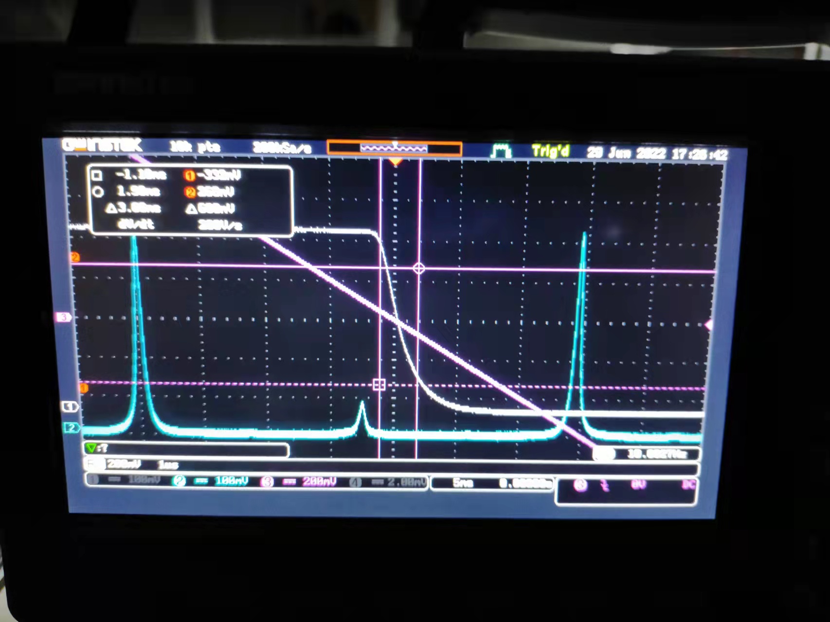
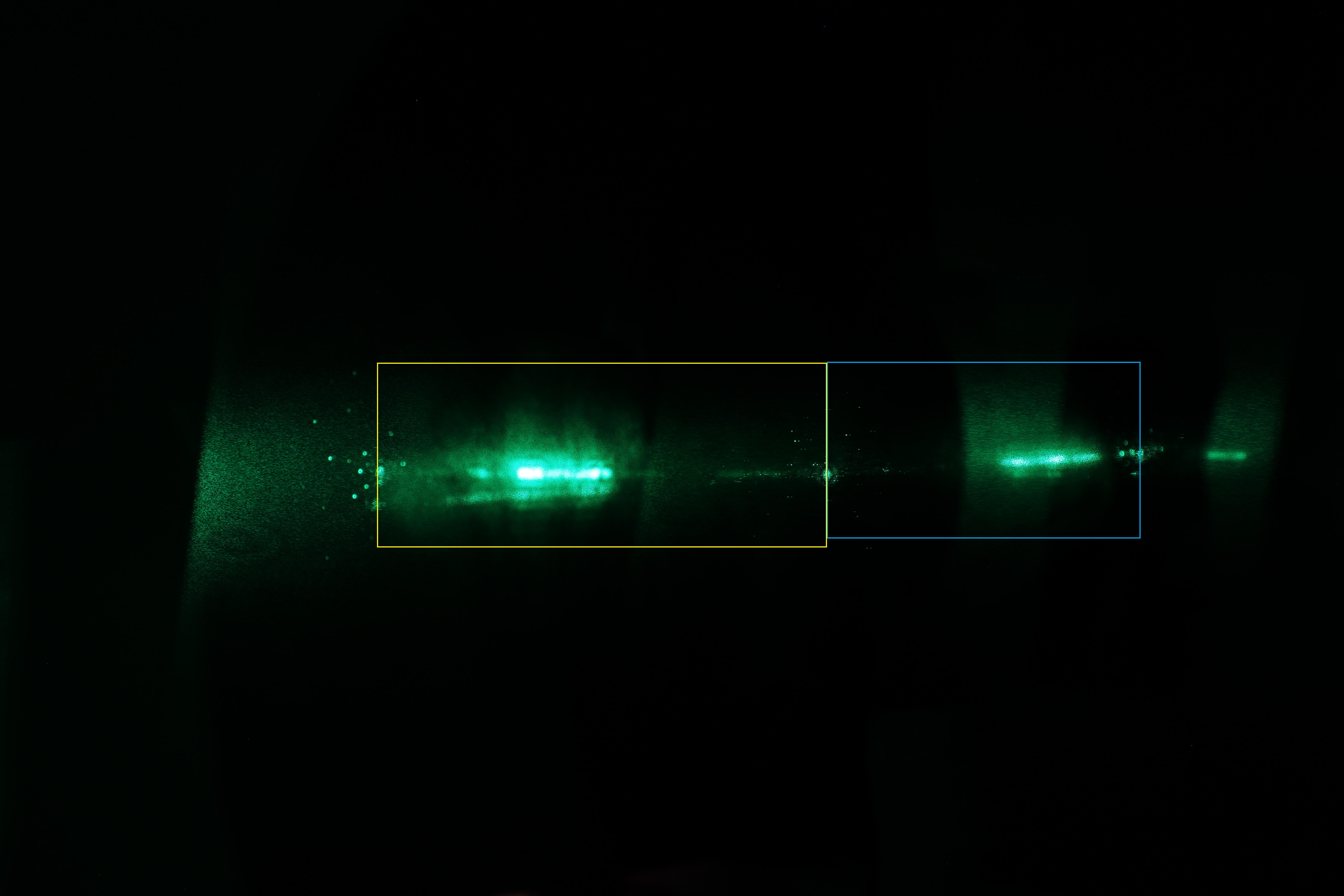
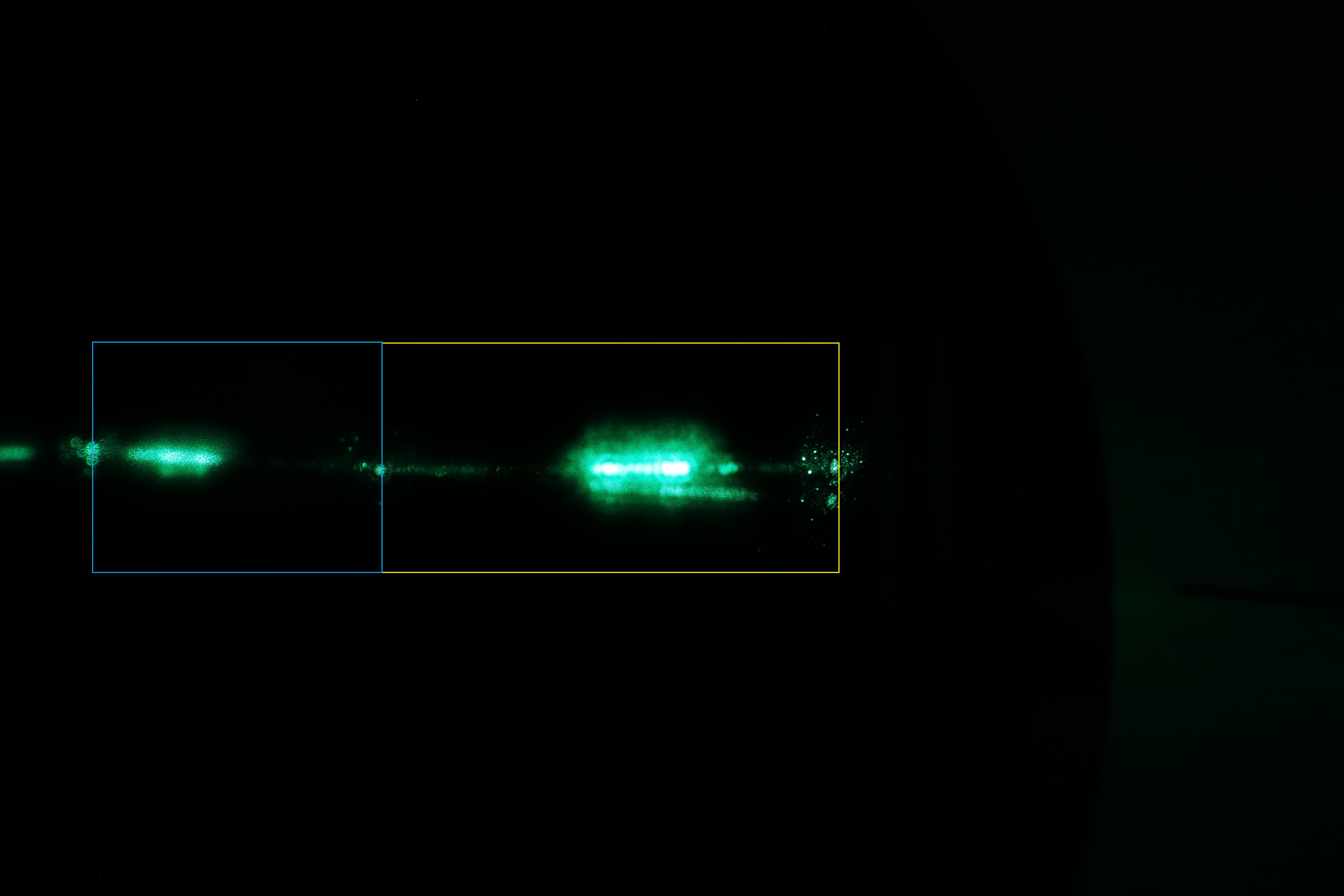
Because the ratio scattering light and inject power is most important, we try to measure scattering of Aztec#3.
Laser power is,
Before iris:8.15mW
After sample:4.55mW
Reflection light:415uW+331uW(415uW is front surface)
In this figure, scattering light is in the yellow box.(Blue box is reflection light by mirror surface)
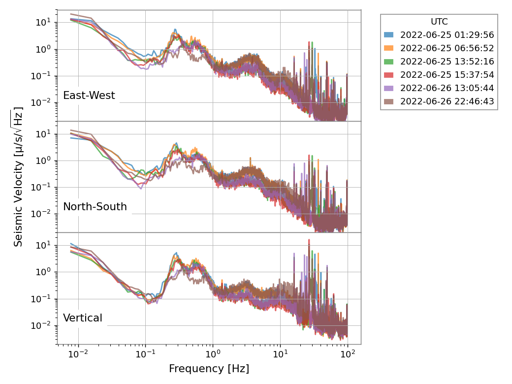
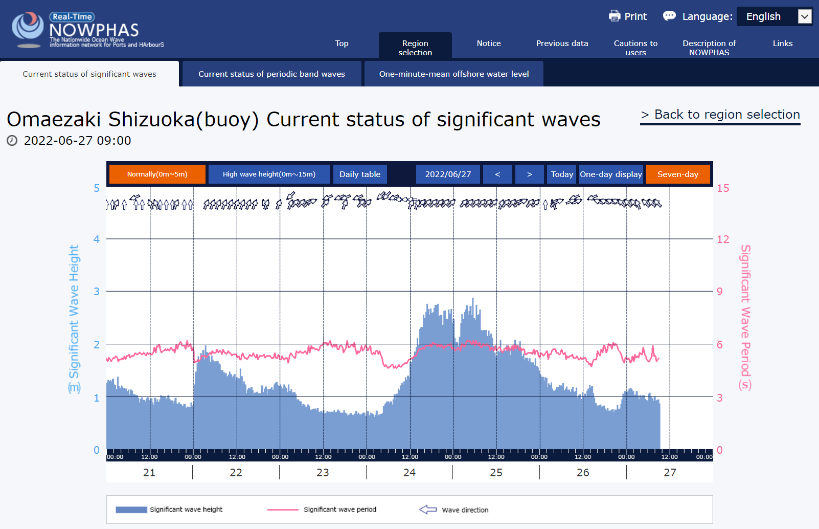
Below 1Hz, microseismic band, the ASD is large on Saturday night. It is consistent with the ocean wave.
At around 3Hz, the ASD is large on Saturday night and Monday morning, and small on Sunday.
Between 10 Hz and 20Hz, the ASD is large on Monday Morning.
Around 30 Hz, sometimes strange bumps are observed.
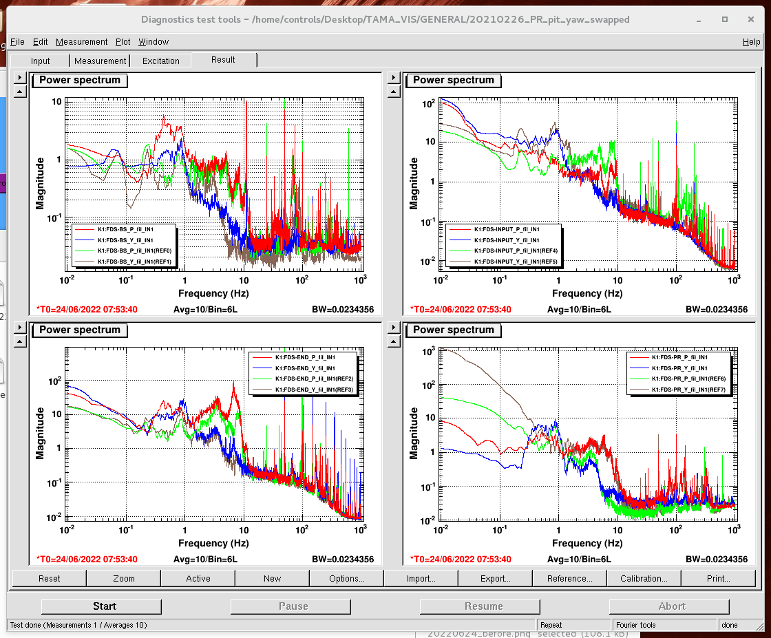
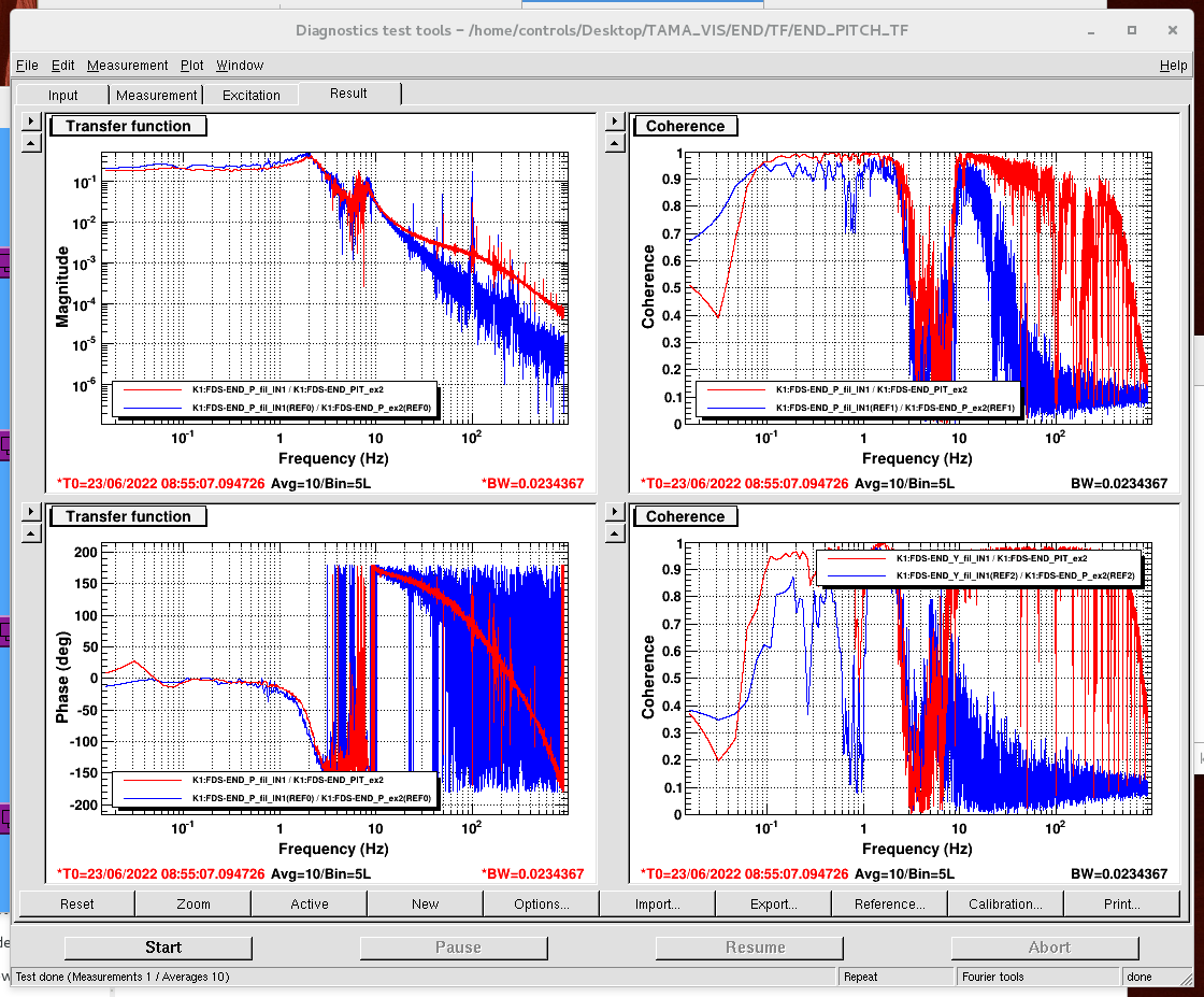
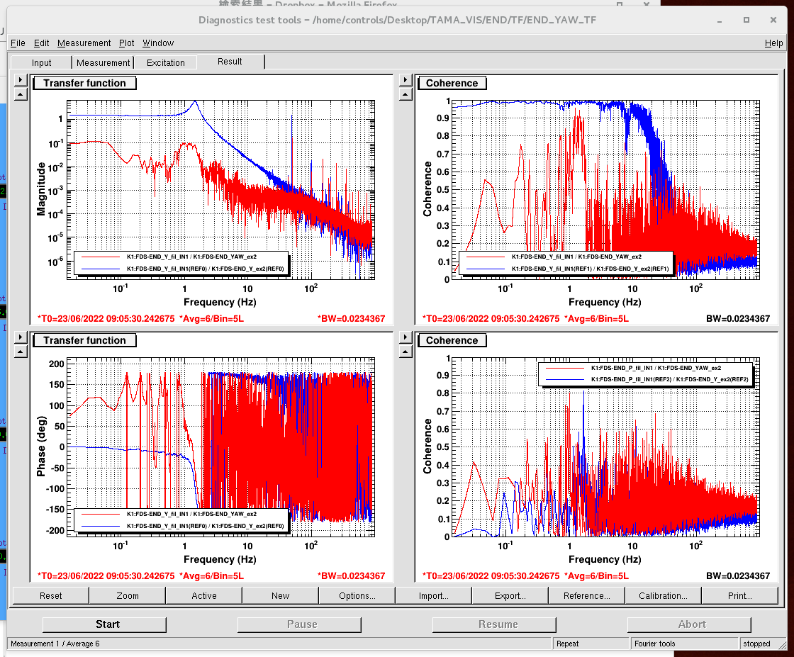
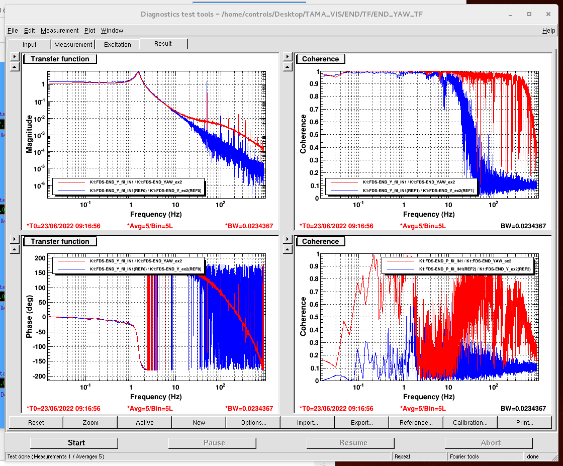
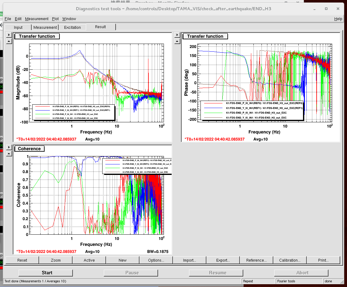
I checked pitch/yaw TF for all mirrors and coil response for all magnets. PR/BS/END are fine.
For INPUT, input oplev spectrum was strange (Fig. 1). Yaw seems fine, but pitch had a huge 50Hz peak. I checked the dark noise and there was no huge 50Hz peak, so the 50Hz peak came from oplev laser source. I power cycled the oplev laser source and then the 50Hz peak disappeared (Fig. 2).
I checked the input pitch/yaw TF. Both of them are smaller than before by a factor of 10, but the shape is fine. I also checked each coil response. They seem fine, but yaw TF is larger than before by a factor of 10 in H2, H4.
[Takahashi, Aritomi, Yuhang, Michael]
Since the END picomotor didn't move, we opened END chamber and aligned FC. We aligned PR and BS to make the green at center of GV between input/BS and at the upper left of first target as reported in elog2935. After we scanned BS alignment, we found the beam at second target.
Then we checked the behavior of END picomotor with old picomotor driver by looking at the green reflection from END mirror at the second target. We connected pitch picomotor to motor A and yaw picomotor to motor B. There are two settings of joystick: SET X and SET Y. In SET X, whatever the selected motor, when we move the joystick in X direction, the beam moves in yaw and when we move the joystick in Y direction, the beam moves in pitch. In SET Y, we can select the motor and the selected picomotor can be moved by moving the joystick in Y direction. We don't understand the bahavior of SET X, but we should use SET Y of joystick. We also confirmed that all motors of old picomotor driver are working.
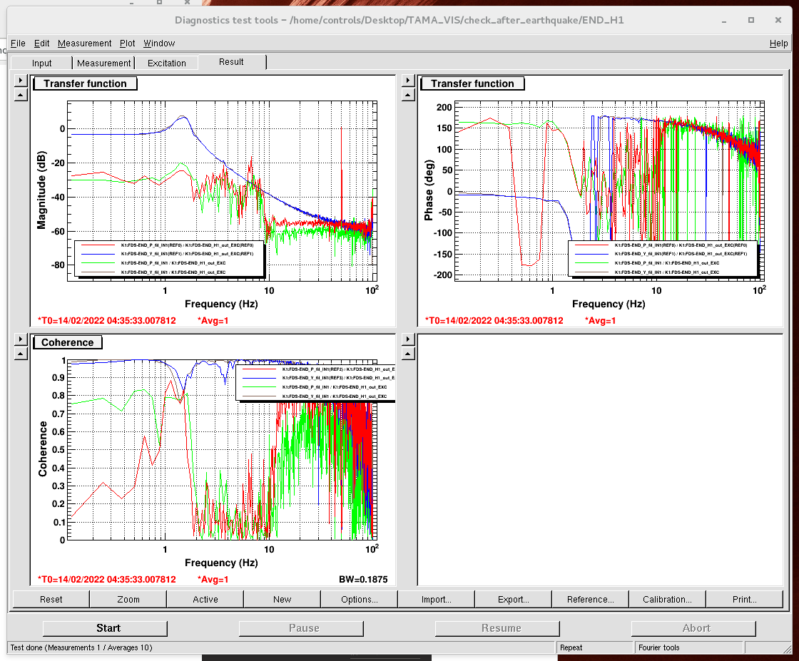
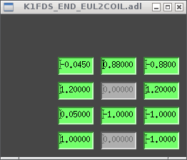
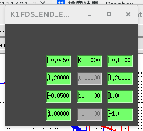
To obtain the END oplev signals, we brought back the Dsub cable from PEM to END oplev signals. We found that when the END oplev beam is blocked, END oplev X and Y show around 2100 and -800 counts, respectively. After we centered the oplev around these values, we checked pitch/yaw TF. The pitch TF was fine (Fig. 1), but yaw TF was strange (Fig. 2). We found that yaw TF becomes fine when we flipped the sign of EUL2COIL matrix for H3 (Fig. 3). When the sign of EUL2COIL matrix for H1 is flipped, the sign of yaw TF is also flipped. We also checked the response of H1, H3 magnets with health check script (H1: Fig. 4, H3: Fig. 5), which also shows the sign of H3 magnet is flipped. This flipping happened when we glued it in elog2900. We flipped all the sign of EUL2COIL matrix for H3 (before: Fig. 6, after: Fig. 7).
Finally we closed the chamber. We will start evacuation tomorrow.
Important note: After we glue the fallen magnet, we should also check the sign of the magnet. If the sign of the magnet is flipped, we need to flip the sign of EUL2COIL matrix for the magnet.
Today I repeated the characterization of an 'unknown sample' (a HWP) using motorized HWP and translation motor.
First, the calibration gave X_cal = 13.3 mm which is compatible with the previous estimation.
Then, I measured the unknown sample retardance to be 0.496 which is expected value.
Next step will be to be able to access photodiode signal on the PC to start the LabView automatization.
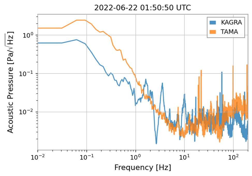
Seismic data of KAGRA is under OMC chamber and the microphone is in the IMC refl.
The large peak at one-handed several-tens Hz of the seismic data is the self-noise. (data sheet)
We try to measure scattering of Aztec 3.
We can take a picture of scattering light.
In this figure, scattering light is in the yellow box.(Blue box is reflection light by mirror surface)
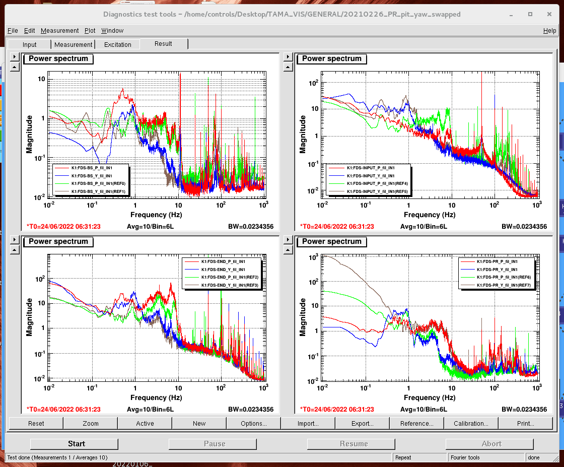
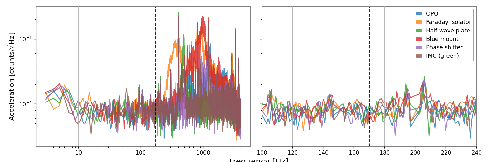
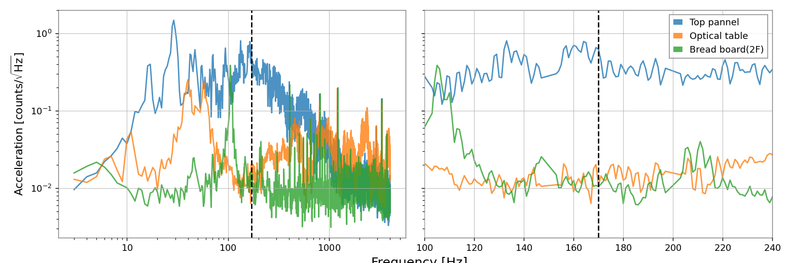
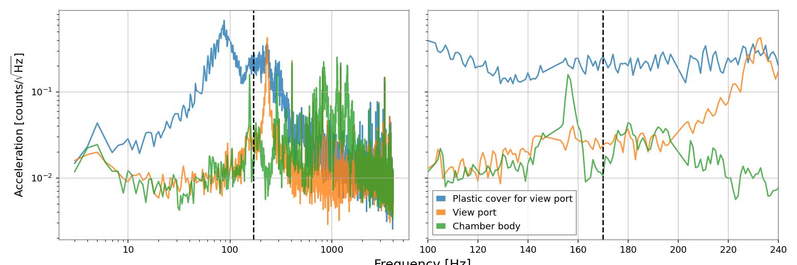
We performed the hammering test for the FC optics, to investigate the origin of the 170Hz noise.
50n Hz peaks are AC power and its harmonics.
The Eigen frequencies of the optics are higher.
The most suspicious object was the chamber.

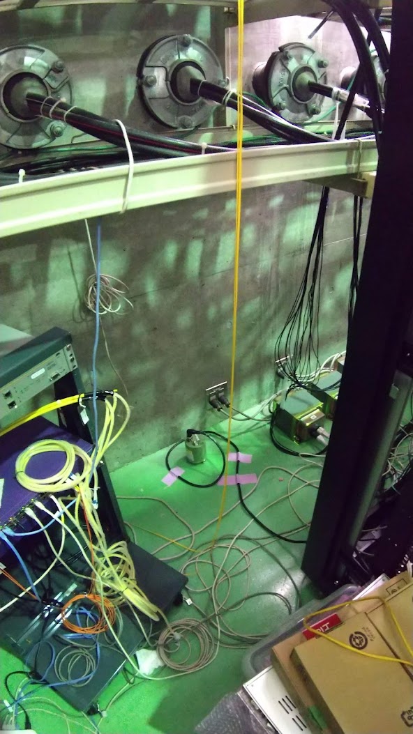
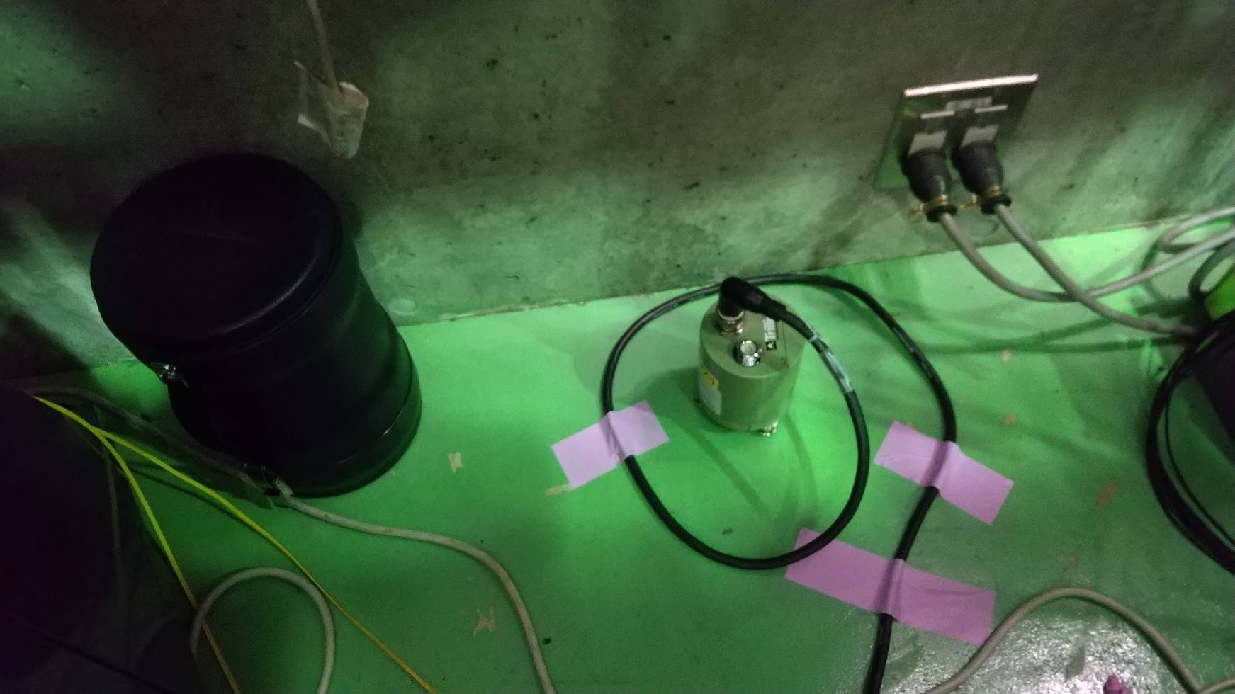
We brought the PEM sensors from KAGRA to TAMA temporally.
* Trillium compact seismometer and its cable
* Whitening filter with DC power supply and D-sub 15pin cable
* ACO microphone, ACO 4ch power supply, and BNC cable
* 3-axis accelerometer and its cable
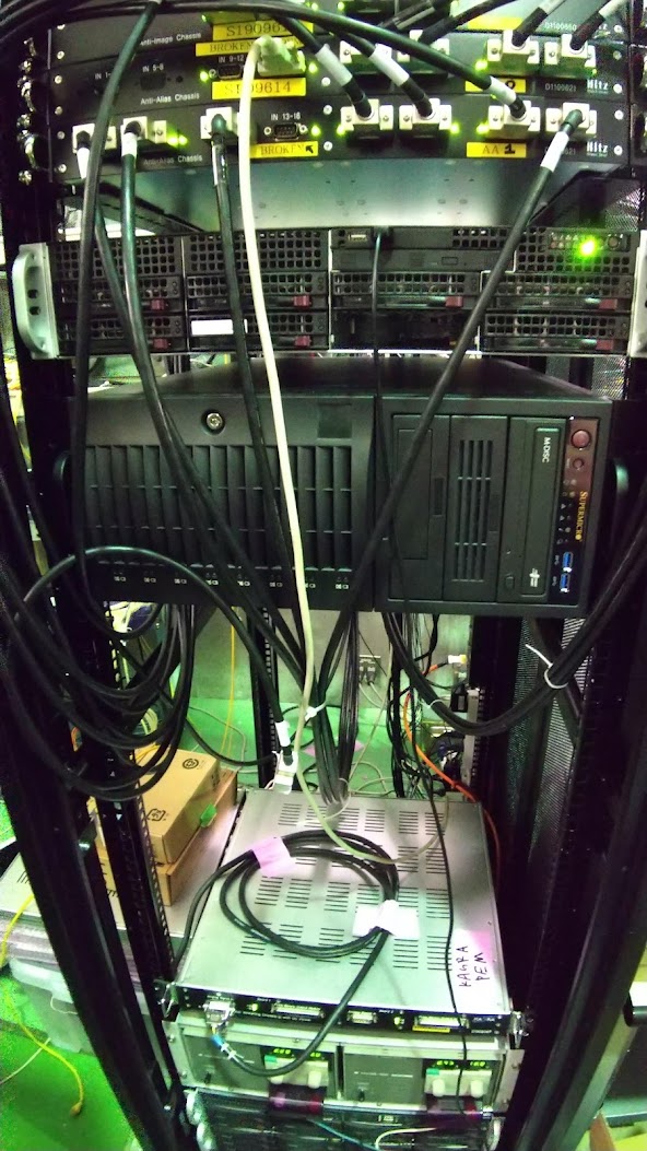
We connected the seismometer and the microphone to the ADC ports.
* K1:FDS-ADCspear_1_OUT_DQ -> Low frequency microphone
* K1:FDS-END_in_HOR_fil_IN1 -> Seismometer East-West
* K1:FDS-END_in_SUM_fil_IN1 -> Seismometer North-South
* K1:FDS-END_in_LEN_fil_IN1 -> Seismometer Vertical
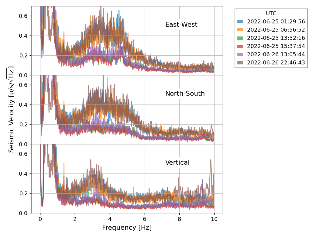
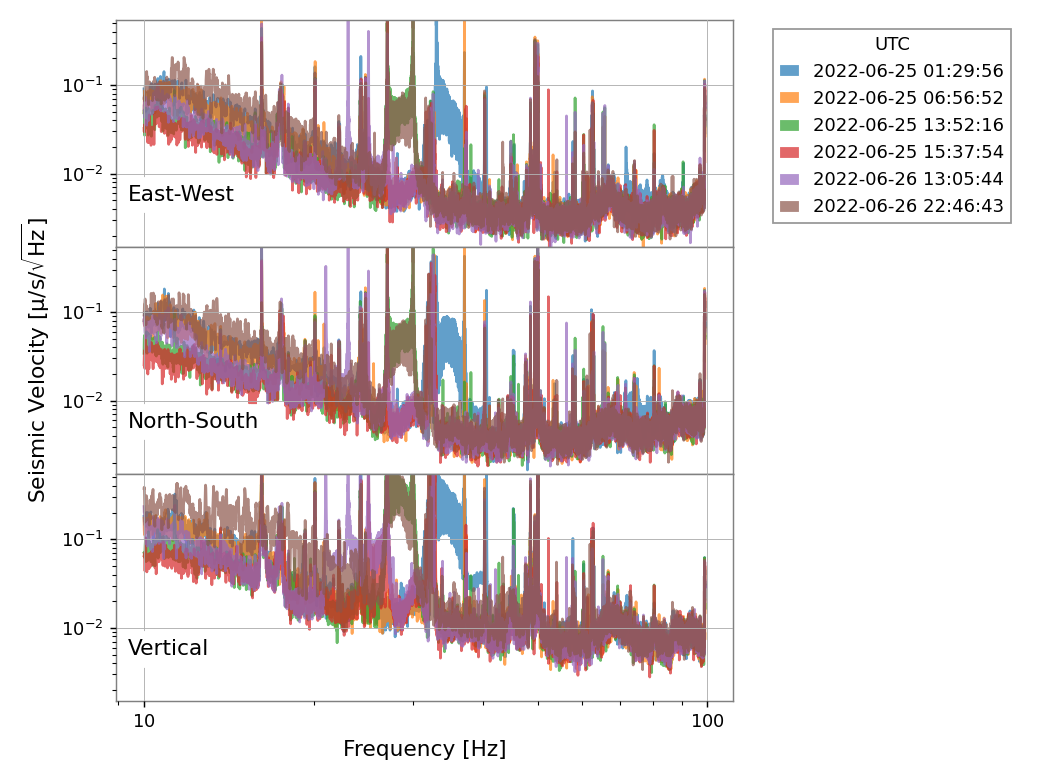
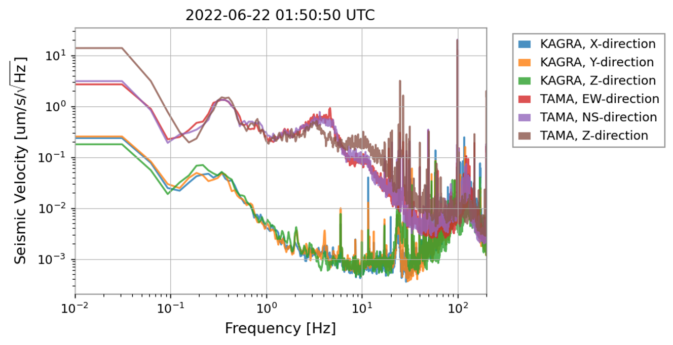
The attached plots are seismic and acoustic data.
The units are "count", not calibrated to um/s more Pa.
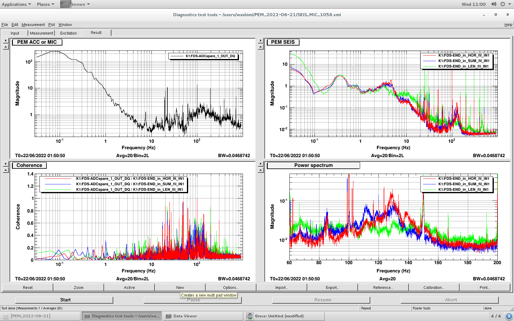
Seismic data of KAGRA is under OMC chamber and the microphone is in the IMC refl.
The large peak at one-handed several-tens Hz of the seismic data is the self-noise. (data sheet)
Below 1Hz, microseismic band, the ASD is large on Saturday night. It is consistent with the ocean wave.
At around 3Hz, the ASD is large on Saturday night and Monday morning, and small on Sunday.
Between 10 Hz and 20Hz, the ASD is large on Monday Morning.
Around 30 Hz, sometimes strange bumps are observed.
Aritomi, Marc, Yuhang
We installed the camera on the PCI setup.
We changed its IP address, installed the Pylon software on the FC pc and can now access it.
Tuning a bit the gamma correction, exposure time and gain of the camera we could not see any IR beam on the mirror.
We will try again later on with a not moving mirror.