NAOJ GW Elog Logbook 3.2

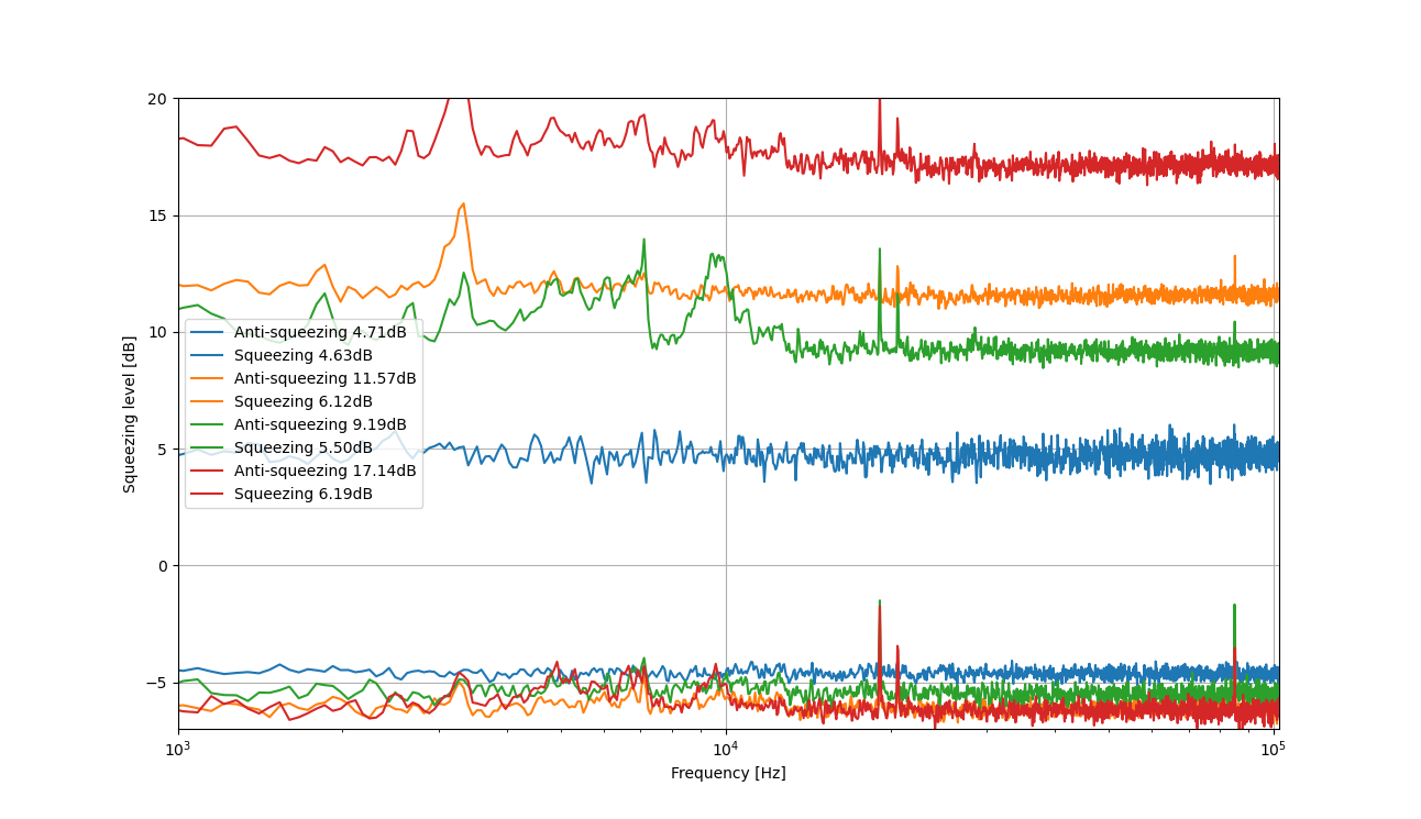
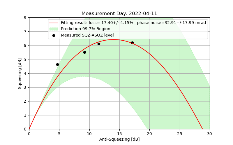
After optimizing homodyne balance, alignment and checking parametric gain, I performed some sqz-asqz measurements. The result is shown in the attached figures. The measurement seems not stable enough to match the theoretical prediction curve in Fig.2. New measurements should be done.
6.19dB squeezing was observed
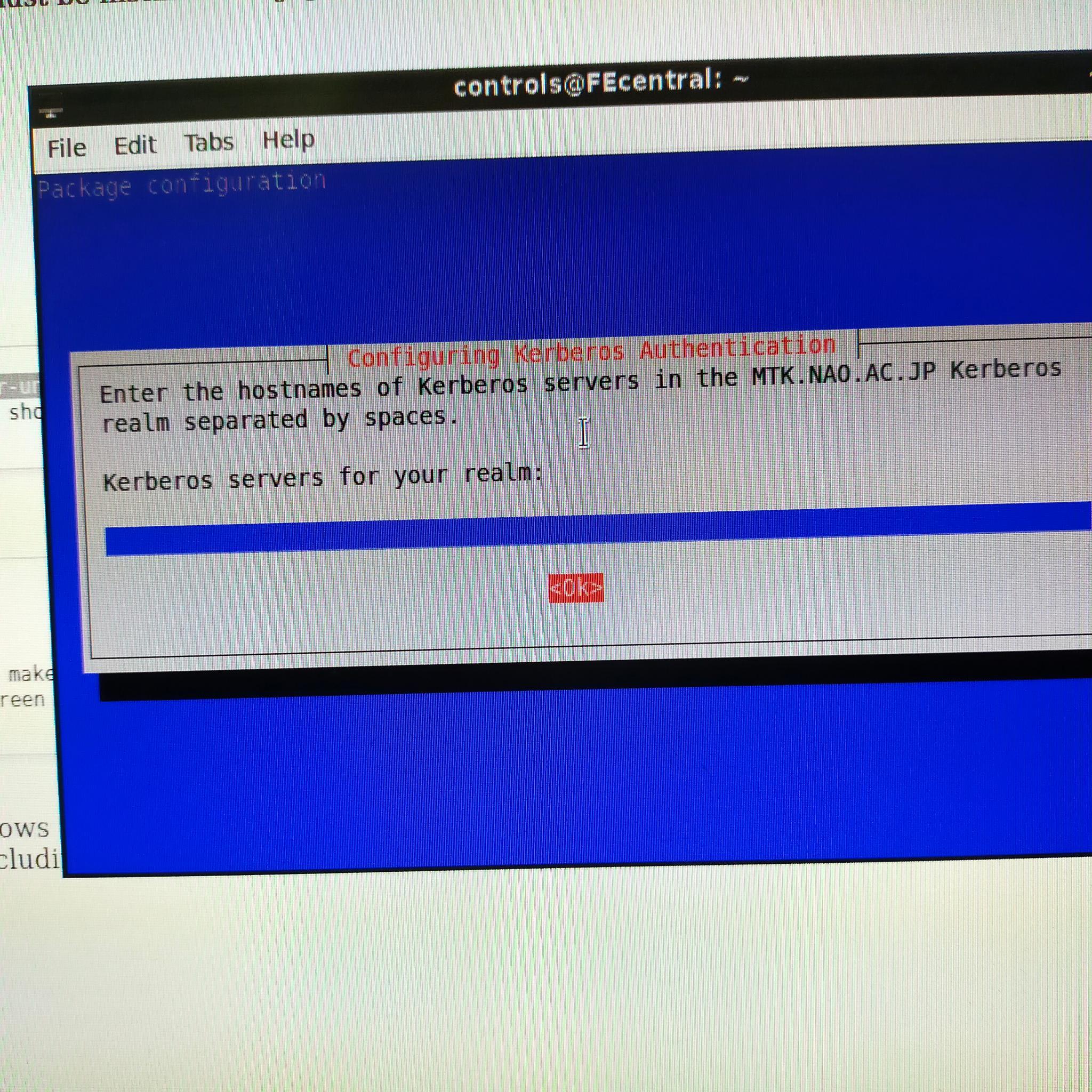
Following on from the previous report, I ignored the Kerberos prompt since it is not used at NAOJ. When it asked me for the hostname and admin password changing server I just left both options blank. After that, the package installation completed.
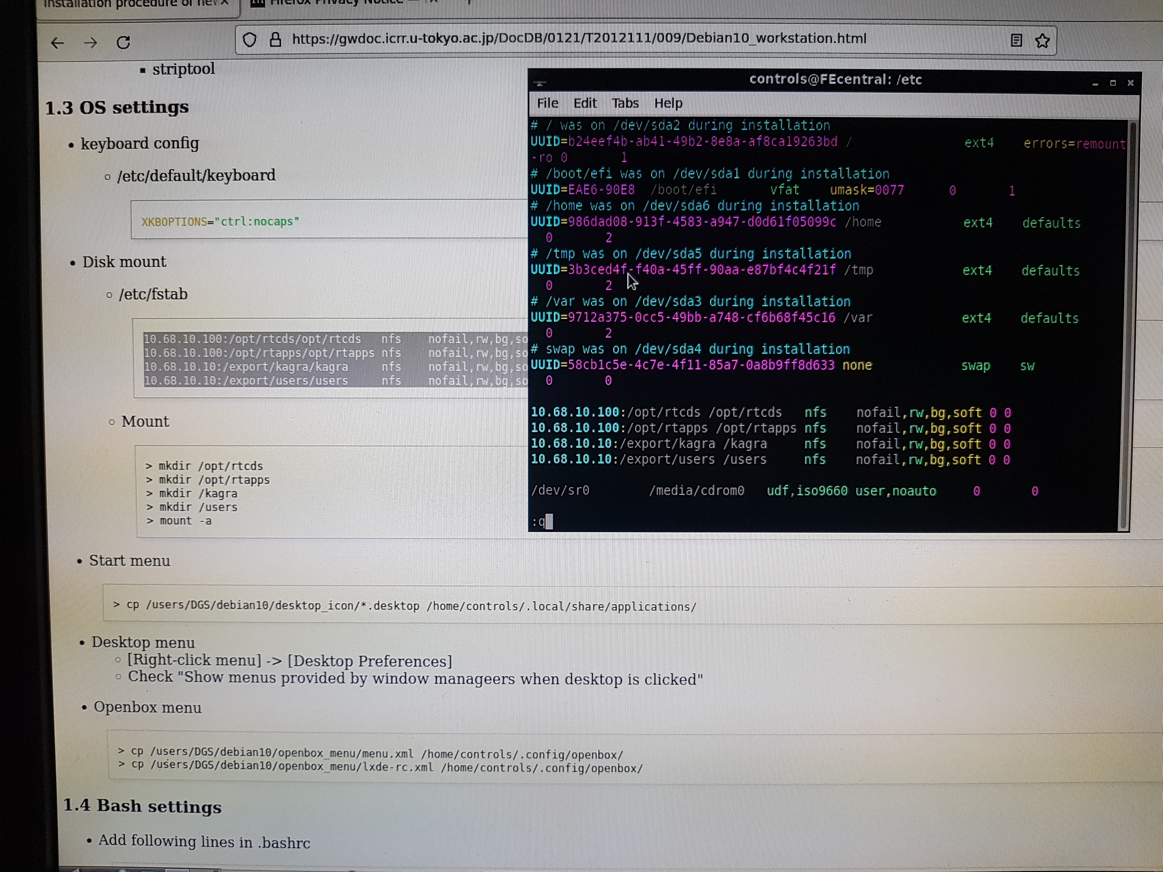
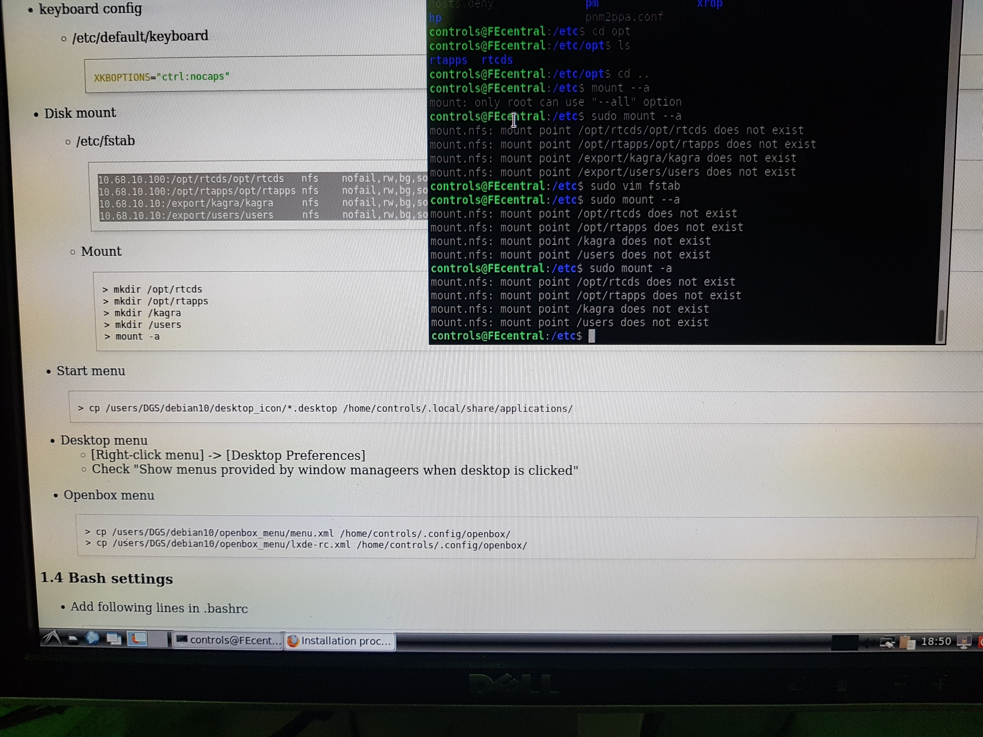
I am now working on 1.3 of T2012111 (Installation procedure of new workstations (Debian10)). I'm a bit stuck on mounting the folders as shown. The instruction page doesn't seem to match the format accepted by /etc/fstb (figure 1) so I added some spaces that seem consistent with how the mount command works - i.e. device directory filesystem options 0 0. My guess is that the device 10.68.10.100:/opt/rtcds is being mounted to the director /etc/opt/rtcds but maybe I should understand which device this actually is. I get the error shown in figure 2, so something is wrong here.
Takahashi-san glued the magnet of input mirror and released the input/end mirrors. We will start the evacuation of input/end chambers tomorrow.
MZ offset: 4.3
Pump power: 29.4mW
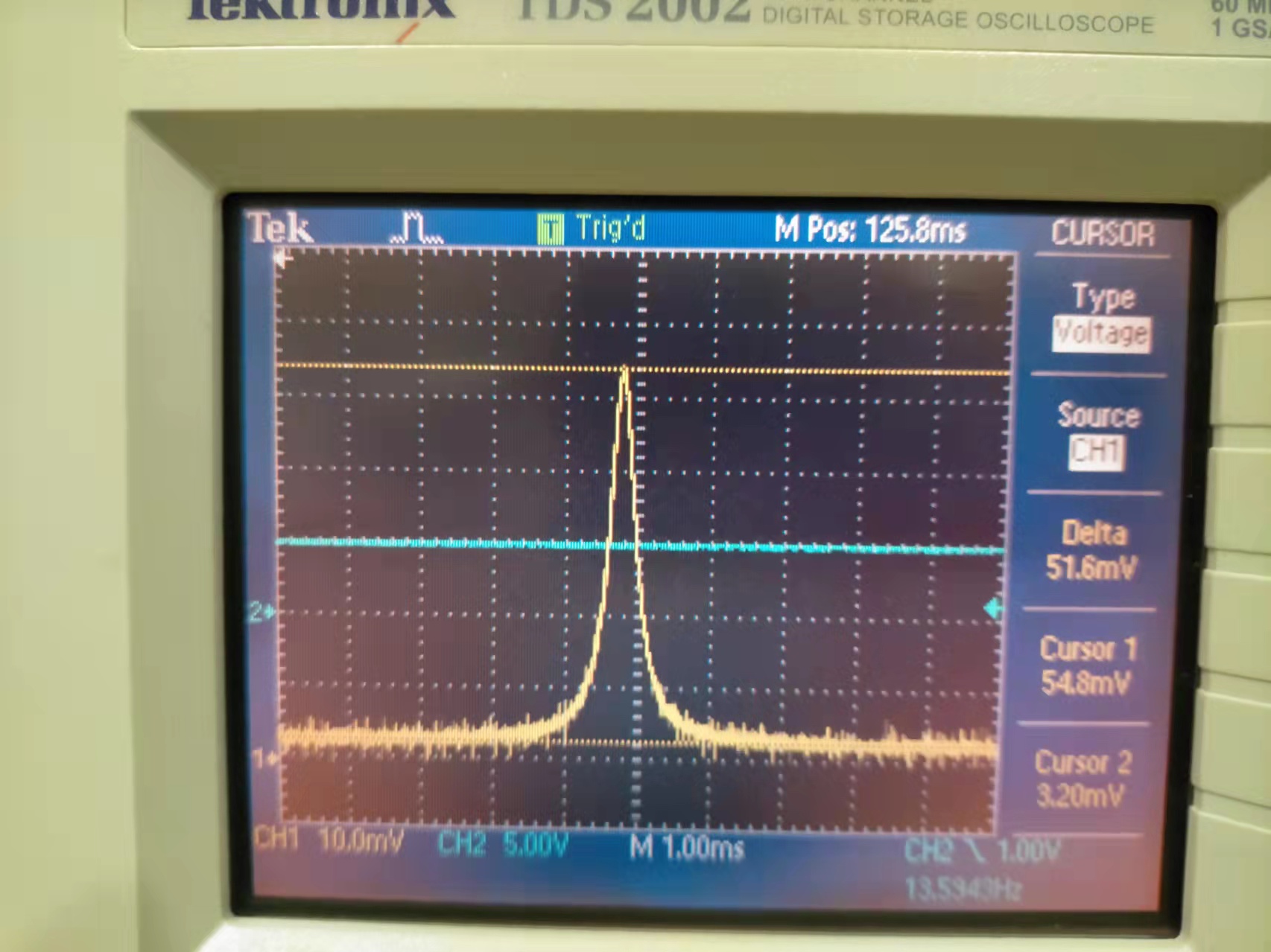
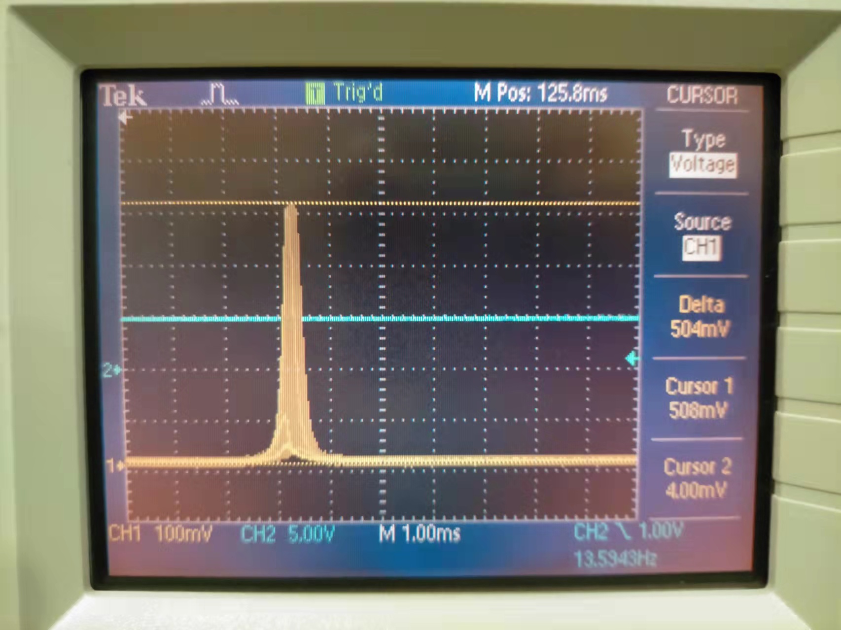
Parametric gain: 504/51.6 = 9.8 (Done by scanning OPO and check BAB transmission. The gain is the ratio of Airy peaks for BAB without pump and BAB with 29.4mW pump. The pump phase was continuously scanned.)
This parametric gain is consistent with old measurement.
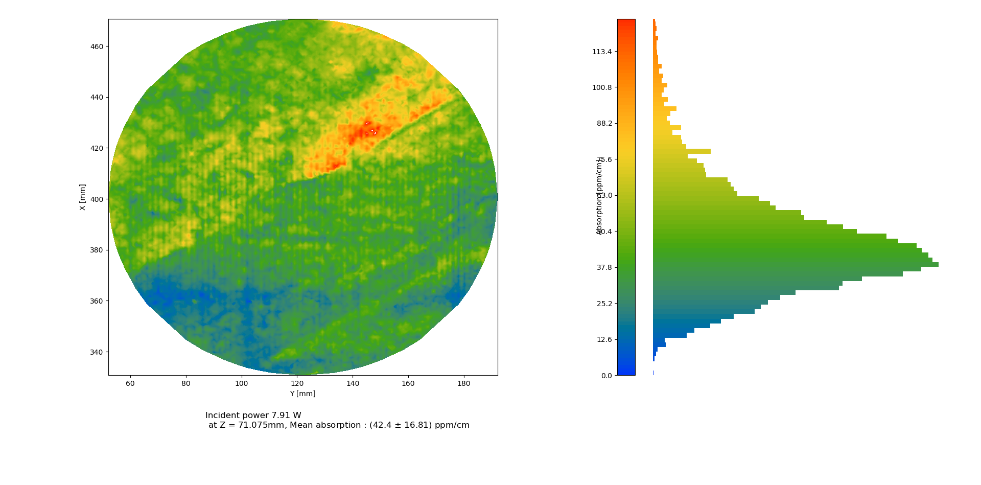
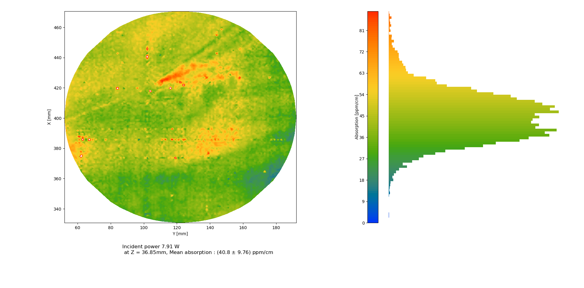
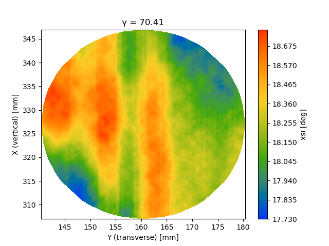
During the weekend the first two XY maps.
The maps are attached.
Here the position and average.
Z= 71.075 (center), mean absorption: (42.4 +/- 16.8)
Z= 36.85, mean absorption: (40.8 +/- 9.7)
Additional maps.
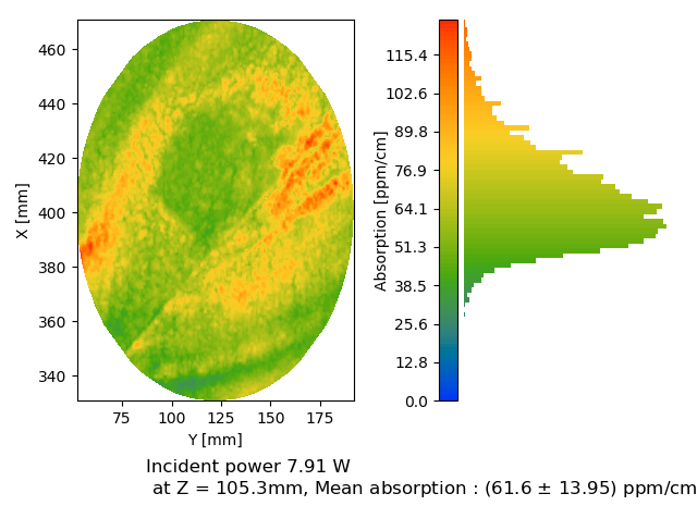
Here the position and average.
Z=105.3, mean absorption: (61.6 +/- 13.95)
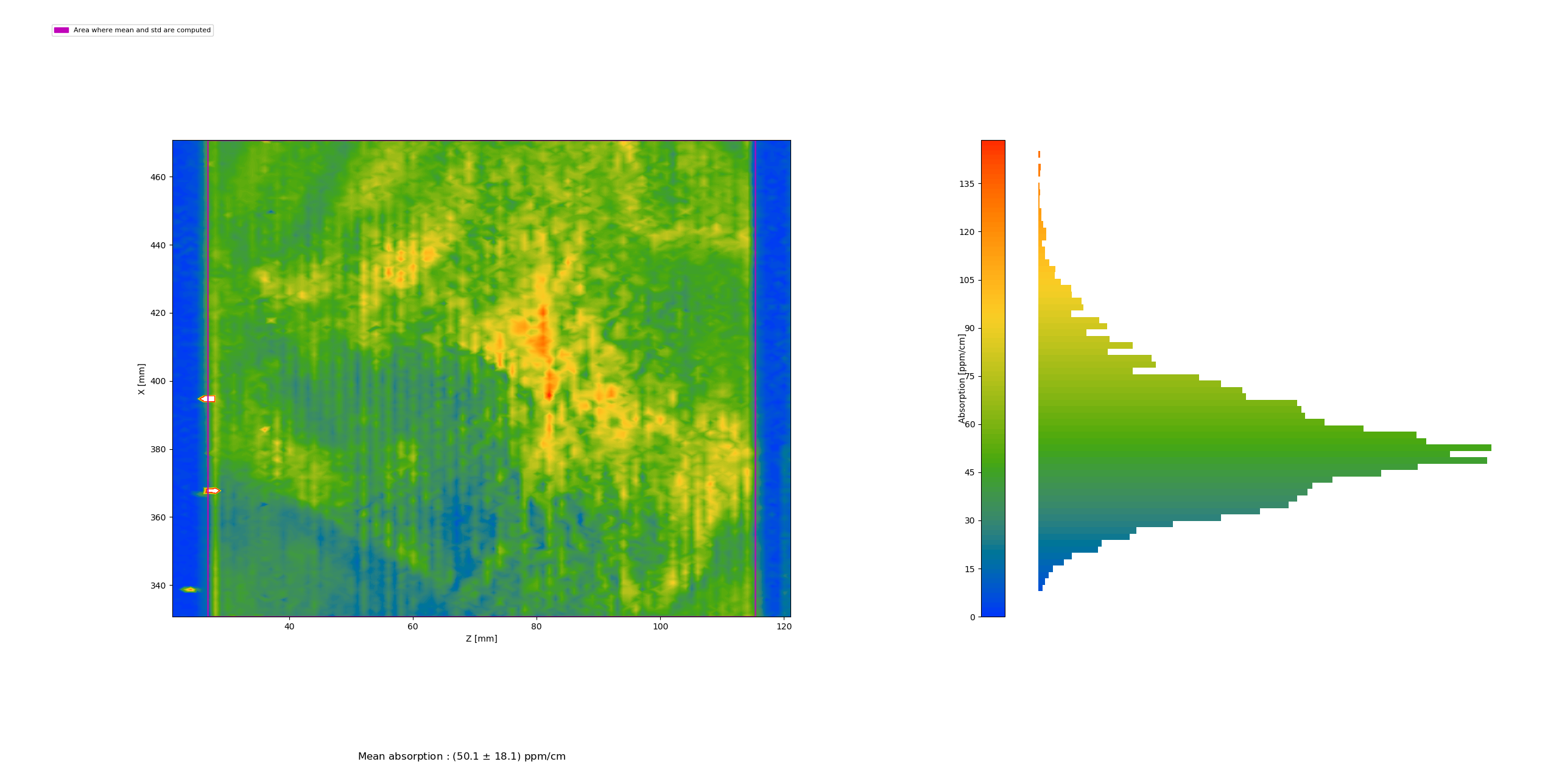
XZ map, mean absorption: (50.1 +/- 18.1)
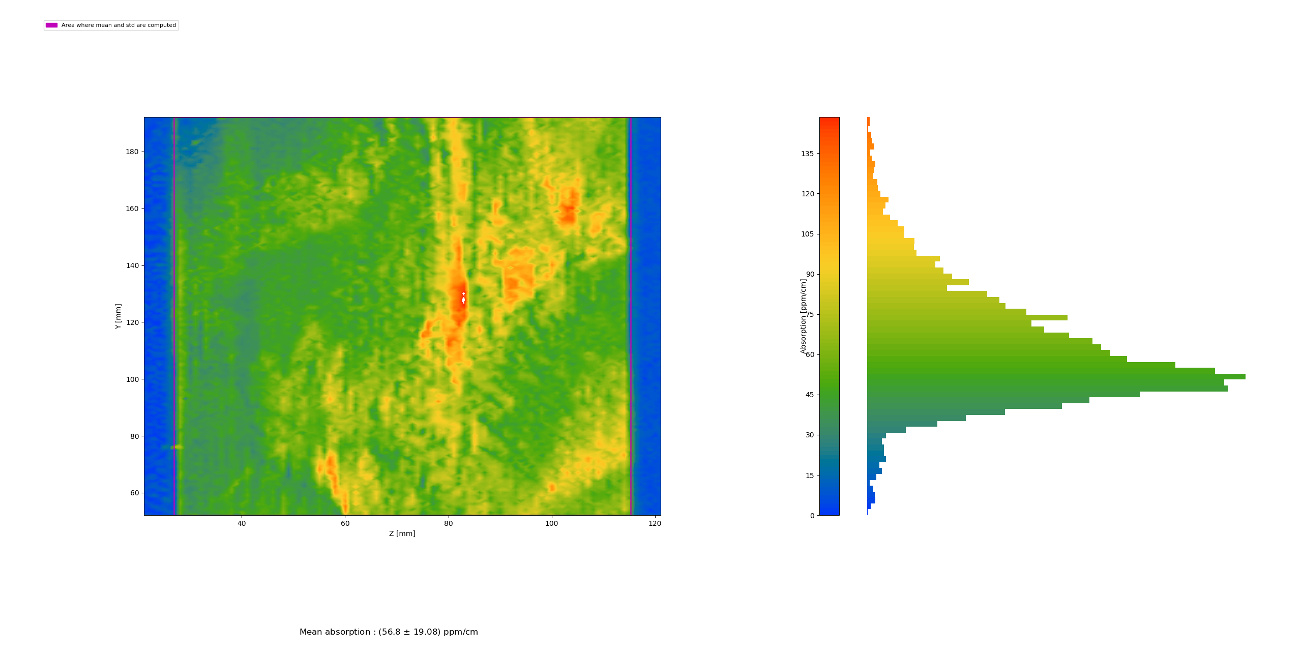
YZ map, mean absorption: (56.8 +/- 19.1)
Michael and Yuhang
After pointing out the place where issue appears in elog2916, we followed the suggestion from Pierre and checked the resistor connect through J10.
1. We disconnected three pins of J10.
2. We put resistor meter between these pins. It was found that the resistor between blue and black wires becomes infinity after touching wires.
3. We peeled off the heat shrinkable tubing for black wire at the place of connecting to potentiometer. But no issue was found.
4. We peeled off the heat shrinkable tubing for blue wire at the place of connecting to potentiometer. We found the inner steel part of the wire has broken.
5. We soldered the broken blue wire.
6. We tested OPO locking servo and found it worked again. But we will see if it always work in the next week or so to confirm its recovery.
Michael and Yuhang
We found the new way of fixing lens causes the problem of BAB OPO transmission to drift. This is the second lens we have in the transmission of OPO along the FIS measurement path. So we need to find a new way to fix this lens.
Now we put it on a pedestal pillar. After doing so, a large portion of p-polarization appears. Before removing this p-pol, it composes of ~5% of total power. However, we found that we could convert p-polarization completely to s-polarization by tilting HWP.
Marc, Michael, Yuhang
It was reported in elog2627 that we have problem of OPO locking servo, which works from time to time.
To solve this problem, we contacted Pierre for suggestions. Now, it becomes clear where the problem is from.
Firstly, we need to notice that we should check the OPO locking servo circuit when 'servo output' is just an offset. The test result reported in this elog is in this situation.
We found a triangular wave at J10 Pin3 but not at J10 Pin2. According to Pierre, this is related to the 'amplitude' potentiometer. We will check the impedance between J10 pin1/pin2/pin3. According to Pierre, the total impedance should be about 2k. If not, we need to buy a new one and replace it: Bourns (3590S-2-503L). We should make sure there is no issue for this potentiometer soldering.
Marc, Michael, Yuhang
Today we installed Debian 10 on the Front End PC of the central building (and during this process removed the 2 previously installed os).
Yamamoto-san kindly gave us instructions for this (and also future) installation.
Documentations can be find from these links or inside KAGRA dropbox (folder Subsystem/FKC/TAMA_DGS/Reference documents) :
[1] https://dcc.ligo.org/LIGO-T1600055/public
[2] https://gwdoc.icrr.u-tokyo.ac.jp/cgi-bin/private/DocDB/ShowDocument?docid=12111
Marc, Matteo
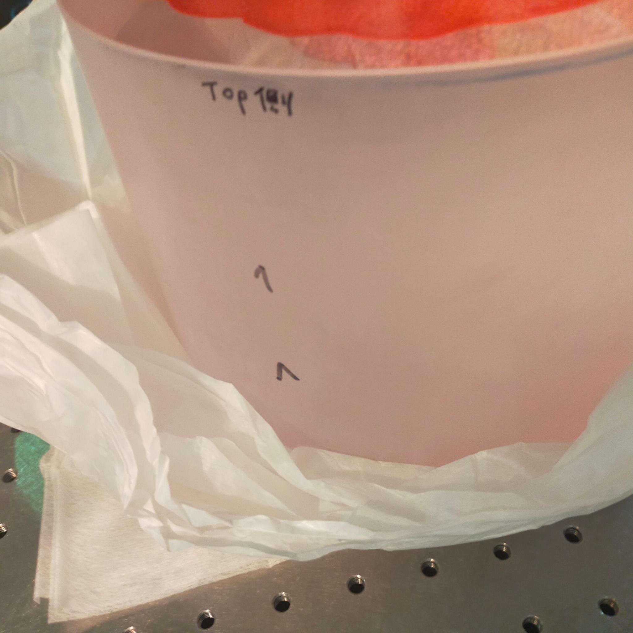
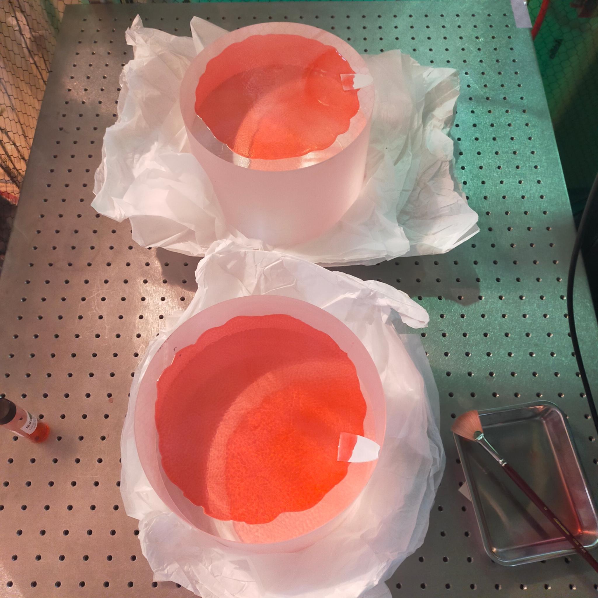
Today we received 2 25 kg substrates grown by AZTEC and repolished by Sigma Koki.
We applied first contact on one of their surfaces and will apply on their other surfaces later today.
On each mirror barrel there is written 'top' followed by some characters.
We added the mirror number (1 or 2) as well as an arrow pointing towards the 'top' sign.
We will use this as our reference for the top part of the mirror during measurement.
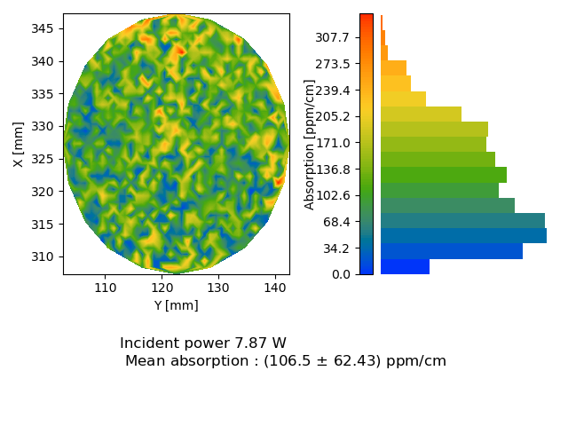
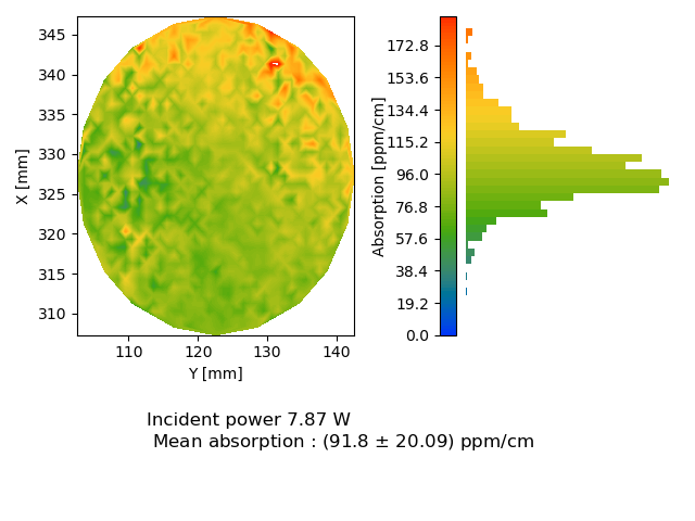
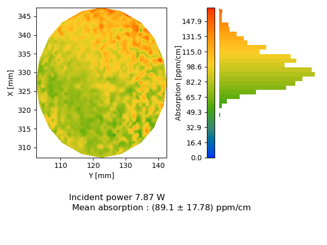
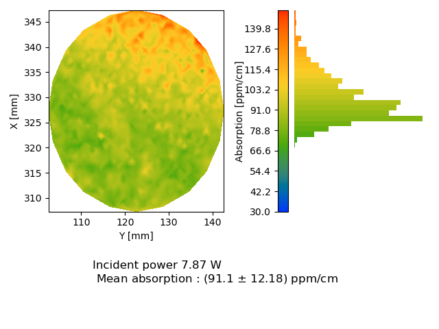
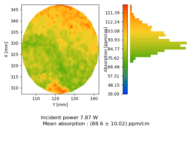
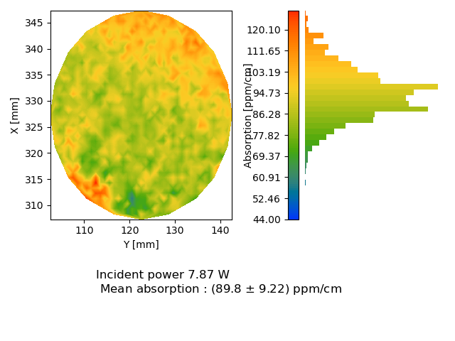
Because new substrates should arrive soon, we decided to pursue our investigation of the annealing of the AZTEC samples by taking several XY measurements with 1 mm step size (instead of 0.25 mm for the previous ones).
The results are reported in the attached entry where only z changes as : 45, 47 49 51 53 56 mm (same order as in picture).
Because of the large step size, it was not so obvious to draw conclusion on the improved/degraded homogeneity with annealing so we decided to start again measurements with 0.5 mm step size.
We are not so sure why the measurement at z = 45 mm (fig 1) has so many values at 0 ppm/cm (the surface should be around 41 mm)
Yuhang and Michael,
We would like to characterise frequency independent squeezing at the best performance we can manage before replacing the OPO. One task is to optimise the alignment of the local oscillator to the alignment mode cleaner, and same for squeezing (i.e. bright alignment beam). Here we checked the alignment of the LO to AMC. We found that the mode matching was still quite good, but there was some undesirable polarization that was leaking. So we added a half wave plate in the LO path just before the homodyne beam splitter. We adjusted the HWP polarization rotation, as well as the tilt and transverse displacement, to remove the unwanted transmission peaks. Then we aligned the LO to reduce higher order modes. The result is shown in figures 1 (TEM00) and 2 (others).
Also we noticed it was quite hot in the clean room. Checking the air conditioning gave a temperature of 25.9 C and humidity 32.8%. Given that it was cold leading up to this measurement we increased the cooling to the cleanroom air conditioner. Some alignment may be affected.
Marc, Matteo
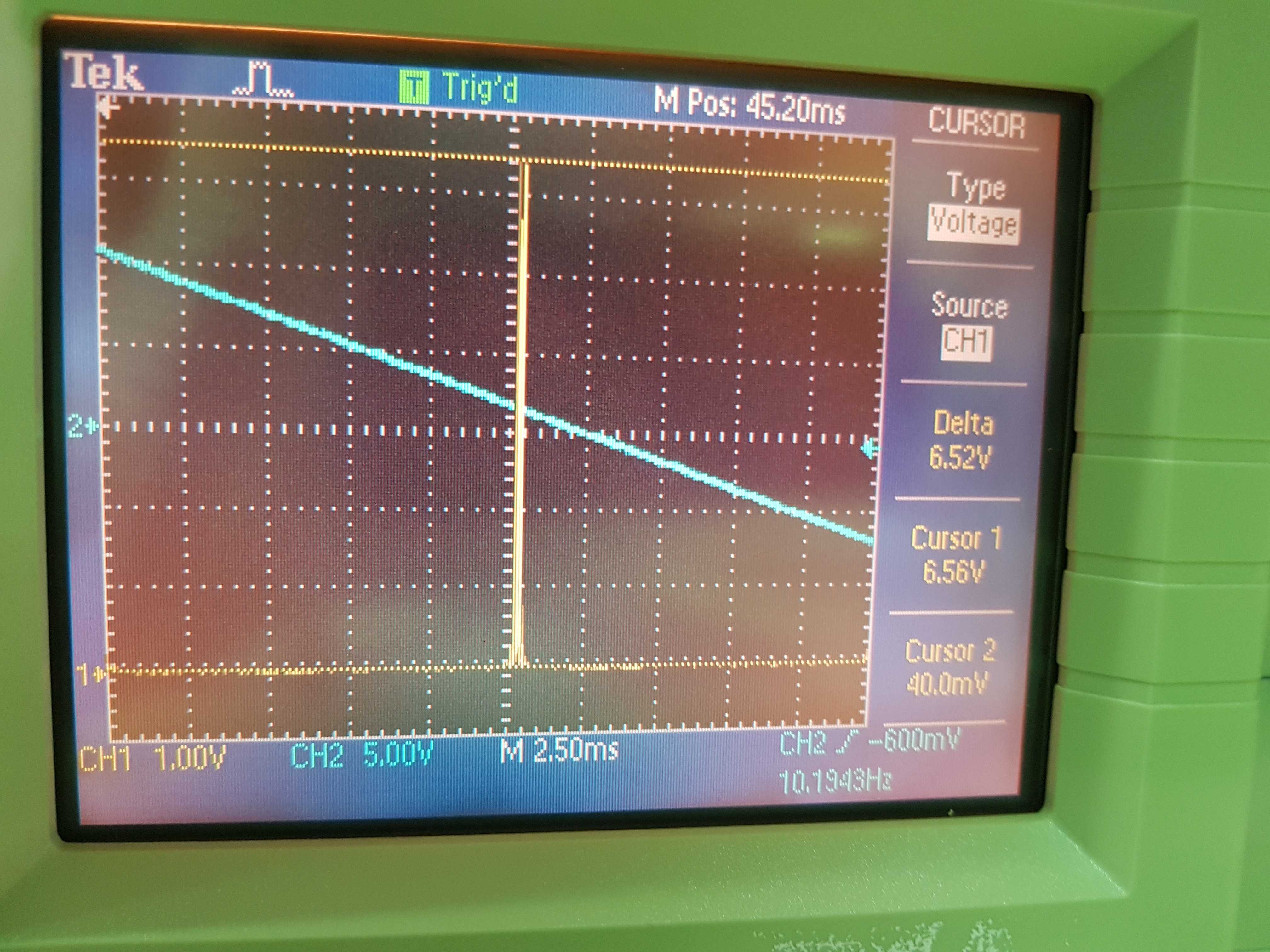
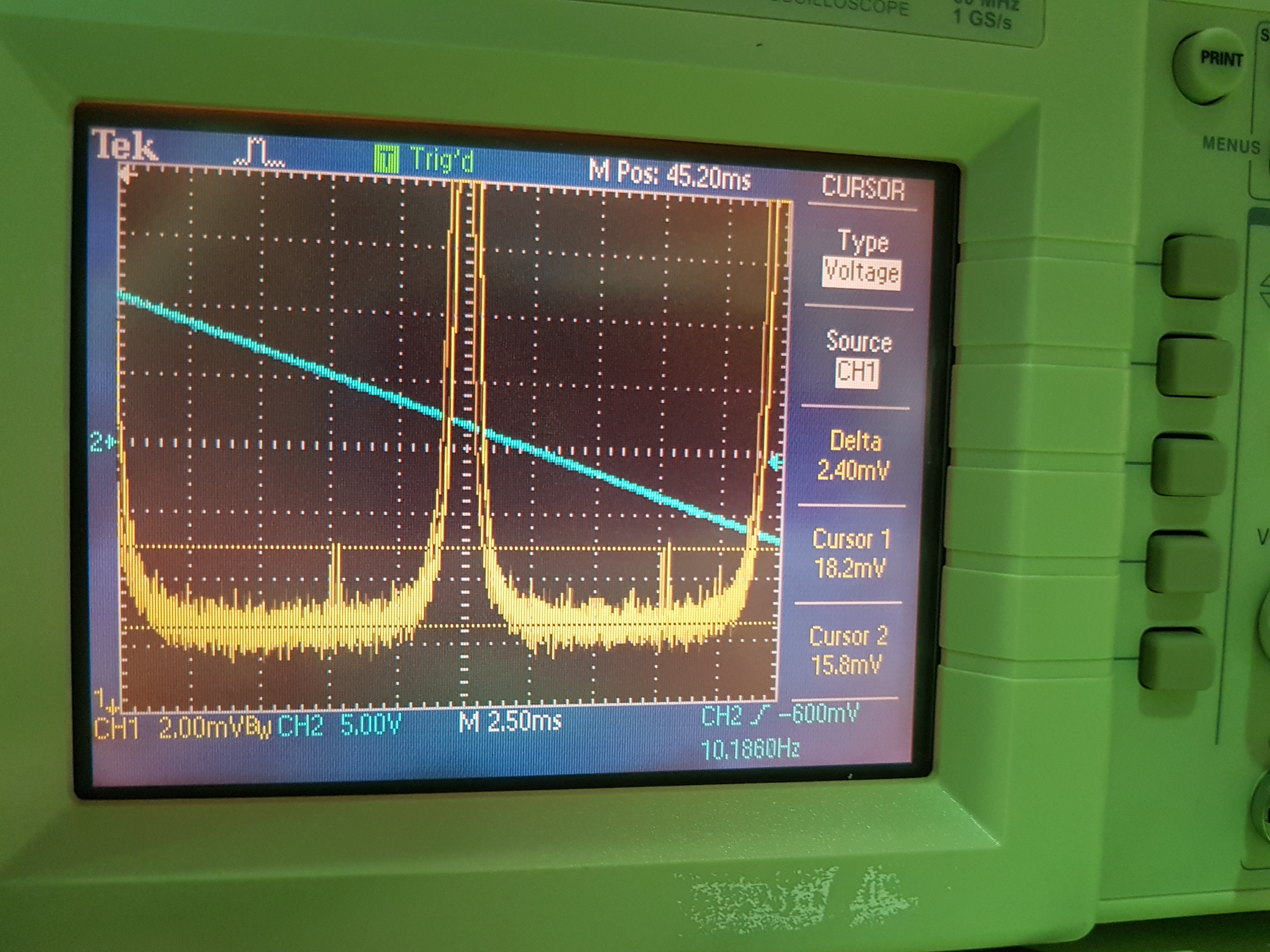
We removed the AZTEC sample and installed the 2 razor blades on the translation stage.
We tuned the input polarization of the pump beam to s polarization (ie hwp angle of 45 deg)
With the translation stage set at z = 20 mm, we measured the distance between the edge of the injection breadboard and the blades to be 92 mm (horizontal one) and 97 mm (vertical one).
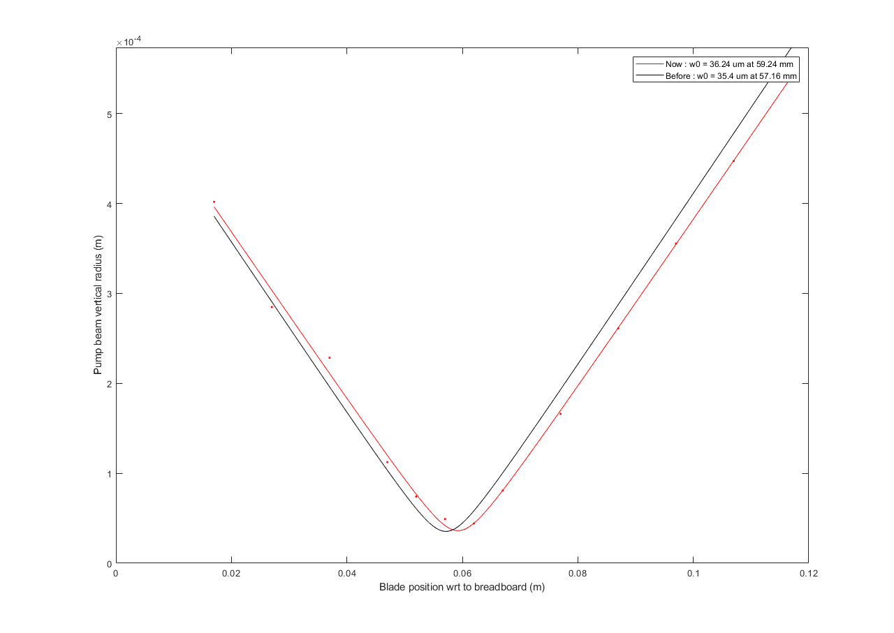
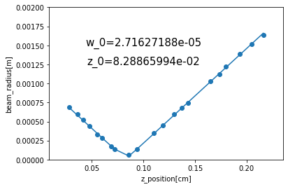
We measured the beam parameters as presented in fig 1 (again the z = 0 mm position is the same as in Manuel PhD) and got w0 = 36.24 um at z = 59.24 mm ie 2 mm further away than previous calibration.
By measuring the distance between the last lens of the inejction breadboard and the blades we tried to improve the vertical incidence angle at better than -0.248 deg.
Using the other blade we confirmed that the horizontal angle of incidence is about 2.7 deg.
For previous surface calibration we used z = 35 mm and z_IU = 68 mm. We did few scans at z = 35 mm and 37 mm but found out that the best calibration was obtained at z = 35 mm.
We measured R_surface = 16.12 /W and R_bulk = 0.6718 cm/W (where z_IU = 67.34 mm).
We reinstalled the AZTEC sample (orientation should be the same as previous measurements) and using the drop in the DC power we measured X_center = 327.293 mm and Y_center = 122.55 mm.
We reinstalled the black cover, all the required beam dumps and increased the laser power to about 7 W.
We started long z scans to find the 2 surfaces of the sample.
At first we found out some strange drop of the dc signal with z about 80 mm. It was because the translation stage was hitting the imaging unit black cover.
After moving it a bit further away we recovered the expected situation and started several measurements in the XY plane with 1 mm step size.
Pictures in the gluing today.
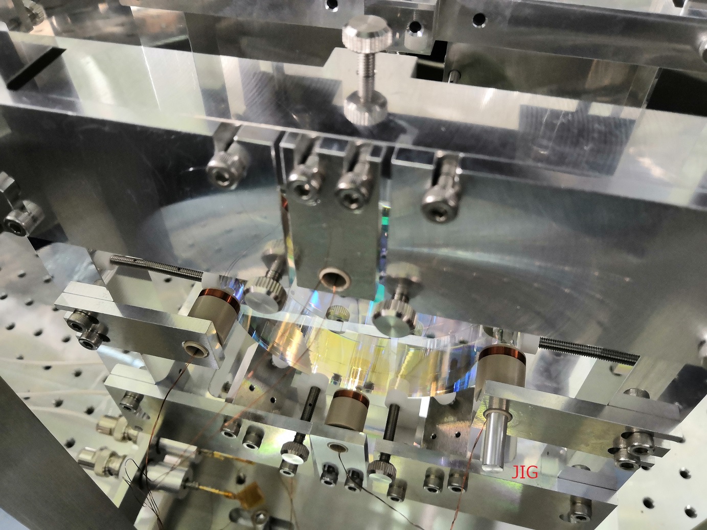
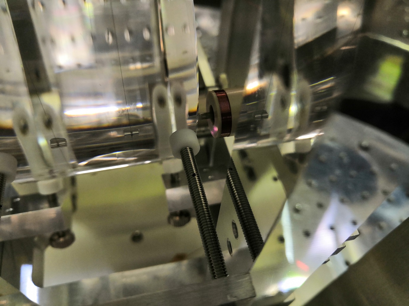
Today Takahashi-san glued the two magnets of end mirror. We will glue the magnet of input mirror and release the input/end mirrors next Monday.
beam waist w_0 = 2.71627188e-05 [m]
waist position z_0 =8.28865994e-02 [m].
I will put lens to put the laser into PD.
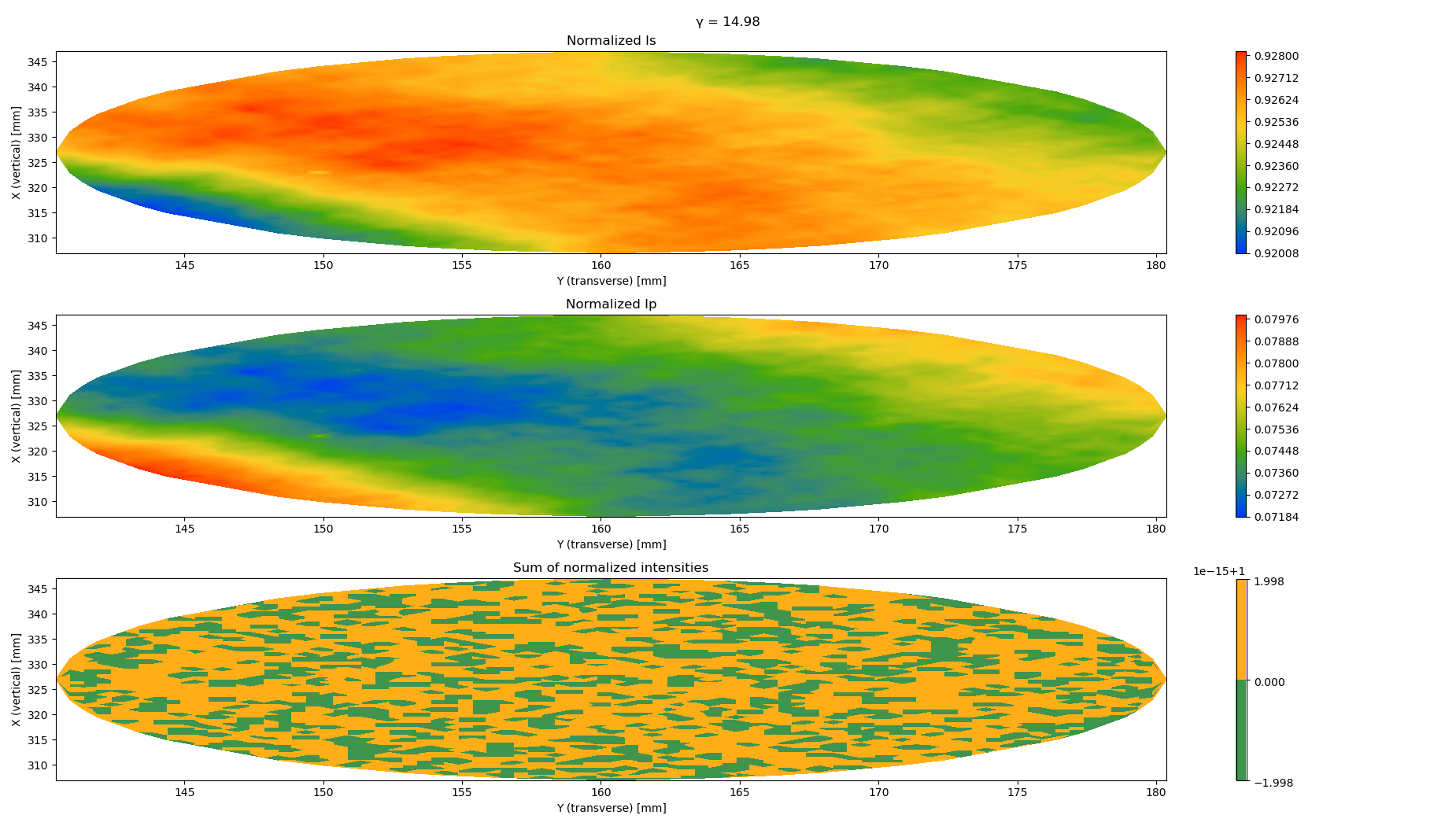
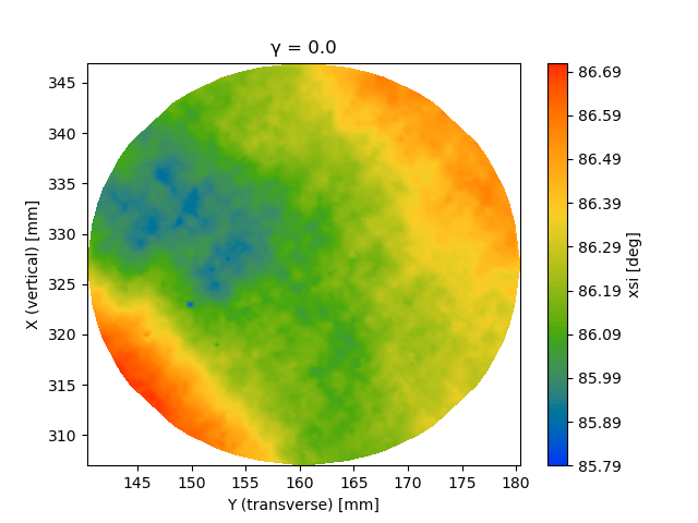
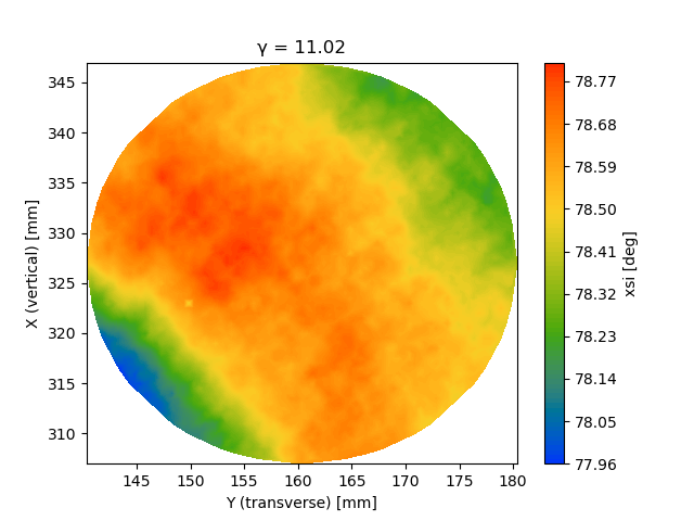
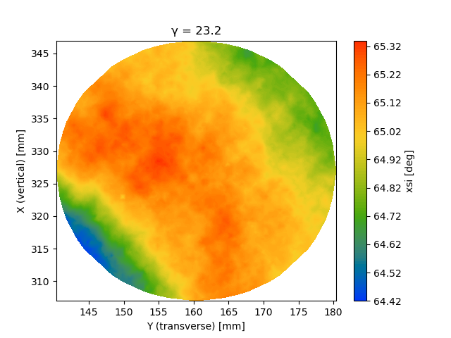
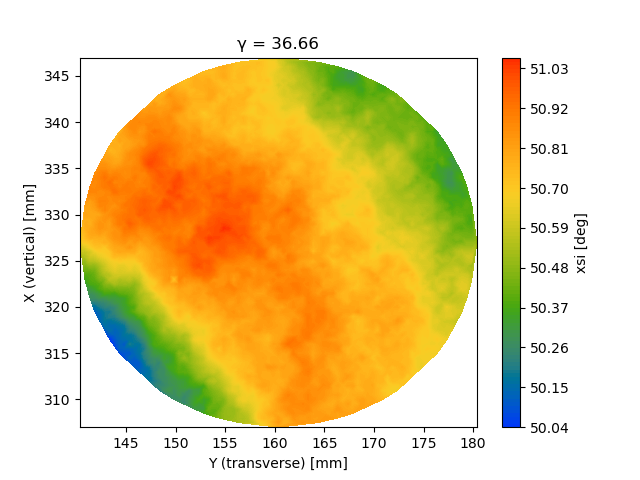
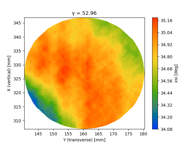
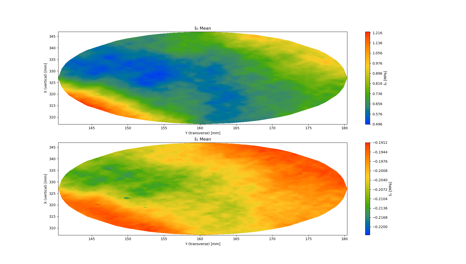
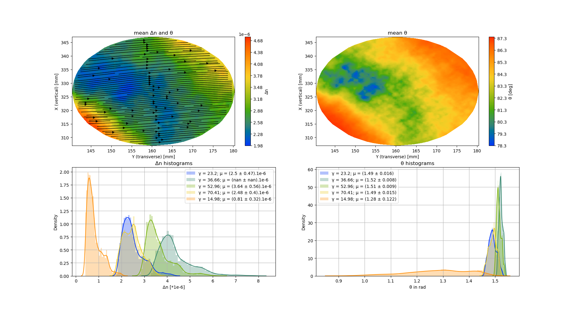
This entry reports the birefringence measurements of annealed AZTEC sample.
Note that here I normalized the s and p polarization power by their sum (see fig 1) so to be independent on the power fluctuations.
This does not affect the results much as we were considering the ratio of these power in any case.
Marc, Yuhang
We installed the GPS cable on the top of all the cables going around the central building up to the new dgs rack.
During this operation, we found the lightning arrester (HP 58505A). It is now installed above the bottom end of the stairs. We still need to connect it to the ground.
We also found out that the gps receiver had the led 'Alarm' on. But because we now have the lightning arrester we are confident that we could connect the gps cable directly to the irig-b card.
We turned on the 2 pc and during the boot we could saw the hardware that we previously installed. The os 'CentOS' is already installed but we don't know the pcs password so we could not investigate more.
We connected the tcp-ip switch to the switch used by the standalone pc with a 10 m long ethernet cable and connected the 2 pcs to this switch.
While turning off the front end pc (offline) it updated some drivers.
Marc, Yuhang
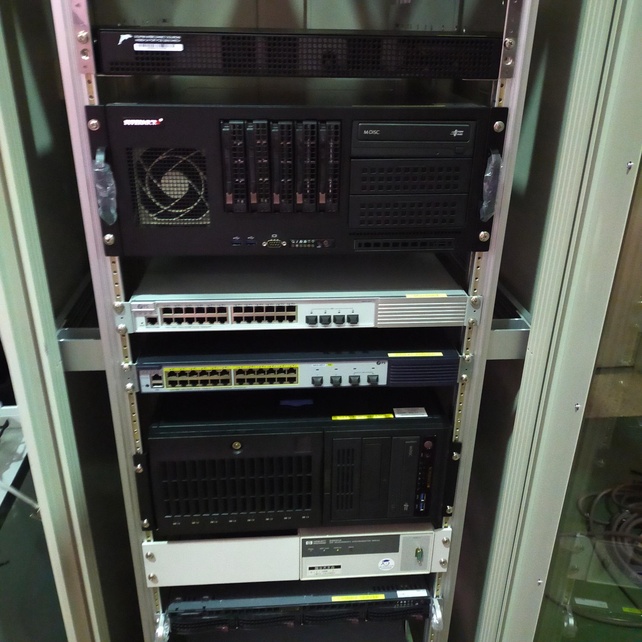
Today we installed all the required pcs and switches for the new DGS in the rack close to the input chamber.
From top to bottom there is :
- dolphin switch
- front end pc for central building
- myrinet switch
- tcp-ip switch
- data concentrator pc
- gps receiver
- camera server
- smart ups
We put label on each component but did not connected anything yet.
The key of the data concentrator pc is on the blue plastic container on the right side of the rack
Marc, Yuhang
We installed the GPS cable on the top of all the cables going around the central building up to the new dgs rack.
During this operation, we found the lightning arrester (HP 58505A). It is now installed above the bottom end of the stairs. We still need to connect it to the ground.
We also found out that the gps receiver had the led 'Alarm' on. But because we now have the lightning arrester we are confident that we could connect the gps cable directly to the irig-b card.
We turned on the 2 pc and during the boot we could saw the hardware that we previously installed. The os 'CentOS' is already installed but we don't know the pcs password so we could not investigate more.
We connected the tcp-ip switch to the switch used by the standalone pc with a 10 m long ethernet cable and connected the 2 pcs to this switch.
While turning off the front end pc (offline) it updated some drivers.
I installed 2 adcs cards in cpu 1 slots 1 and 2 (respective S/N are 210128-11 and 210128-26) and 2 dac cards in cpu 2 slots 5 and 6 (respective S/N are 200813-74 and 200813-40).
It means that one cpu is responsible for adc while another one for dac however Aso-san told us that the manufacturer confirmed that every PCI-e slot should be able to communicate with all cpus so we will have to investigate a bit the BIOS.
The dolphin card is installed on the cpu 2 slot 8.
We are also supposed to install the myrinet connection but it seems we don't have more card with SFP connector so I'm guessing we will connect through ethernet to the myrinet switch.
With the 2 adc and 2 dac cards we have 128 channels available.