NAOJ GW Elog Logbook 3.2

Aritomi and Yuhang
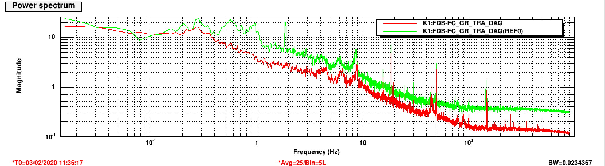
Yesterday, the filter cavity is very stable (red curve). We took the spectrum and compared it with last friday (green curve).
The data is saved in desktop as TRA2.
Pengbo, Simon
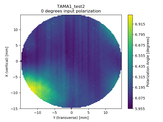
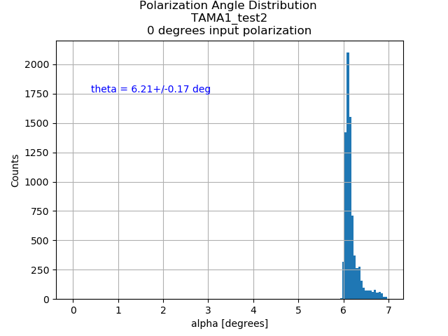
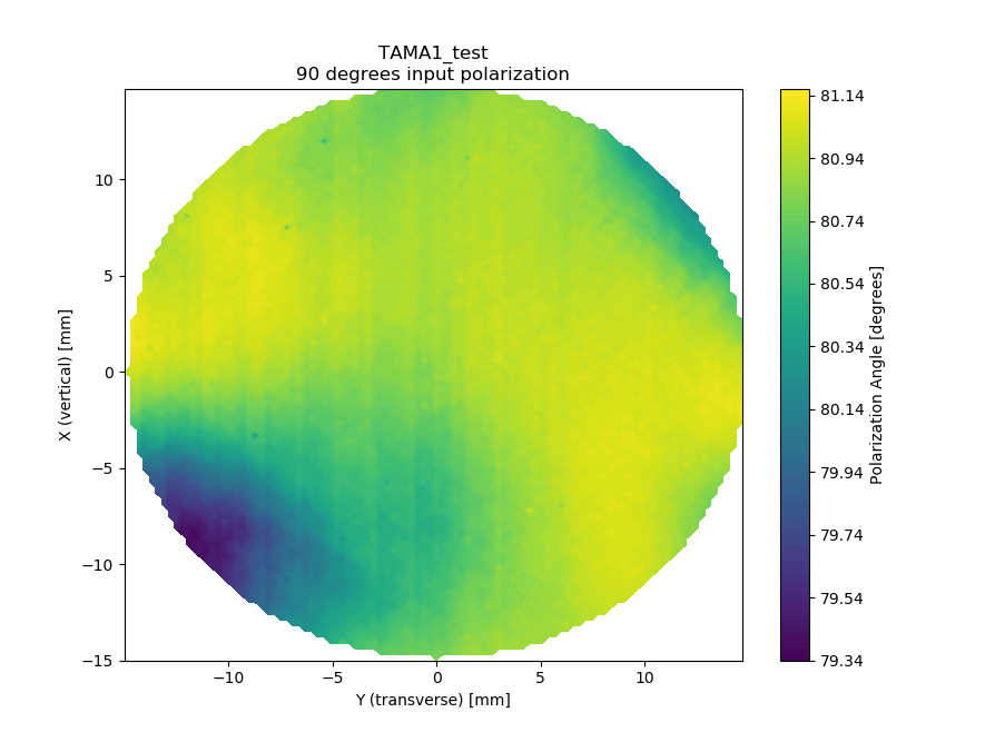
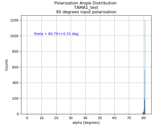
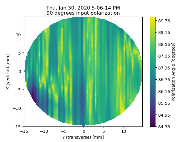
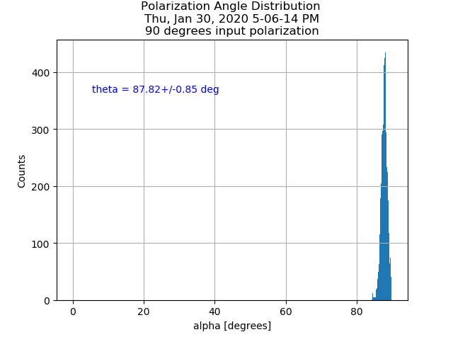
The measurement on the P-pol input birefringence in TAMA#1 is finished. Please refer to the attached pictures.
As can be seen (again compared with the results of the former measurement, see elog entry 1807) we could decrease the number and epecially the strength of the disturbing vertical stripes. Of course, they are still present but note that the inhomogeneity level is quite low. Therefore, also weak remnants of polarization instabilities are easily visible.
| green power (mW) | 0 | 18 |
| OPO temperature (kOhm) | 7.164 | 7.164 |
| p pol PLL (MHz) | 240 (44) | 190 (38) |
[Aritomi, Yuhang]
I fitted the data from 70Hz to 800Hz. Compared with last week's measurement, produced SQZ increased from 7dB to 8.2dB since we optimized OPO temperature and p pol PLL. We found that today filter cavity is very stable and locking accuracy seems better than usual.
One thing we can try is to reduce LO if we can improve backscattering. Also we can try to reduce green power a bit more.
sqz_dB = 8.2; % produced SQZ
L_rt = 150e-6; % FC losses
L_inj = 0.20; % Injection losses
L_ro = 0.11; % Readout losses
A0 = 0.05; % Squeezed field/filter cavity mode mismatch losses
C0 = 0.05; % Squeezed field/local oscillator mode mismatch losses
ERR_L = 5e-12; % Lock accuracy [m]
ERR_csi = 80e-3; % Phase noise[rad]
Last Friday with the help of Lucia we modified end mirror damp loop to improve the performaces in pitch has I did for the input. It seemed good but after that the dithering was not working anymore. So I put back the previous filter and still it was not working. Finally I could make it work again by changing the sign of the loop (End part). Very strange.
[Aritomi, Yuhang, Eleonora]
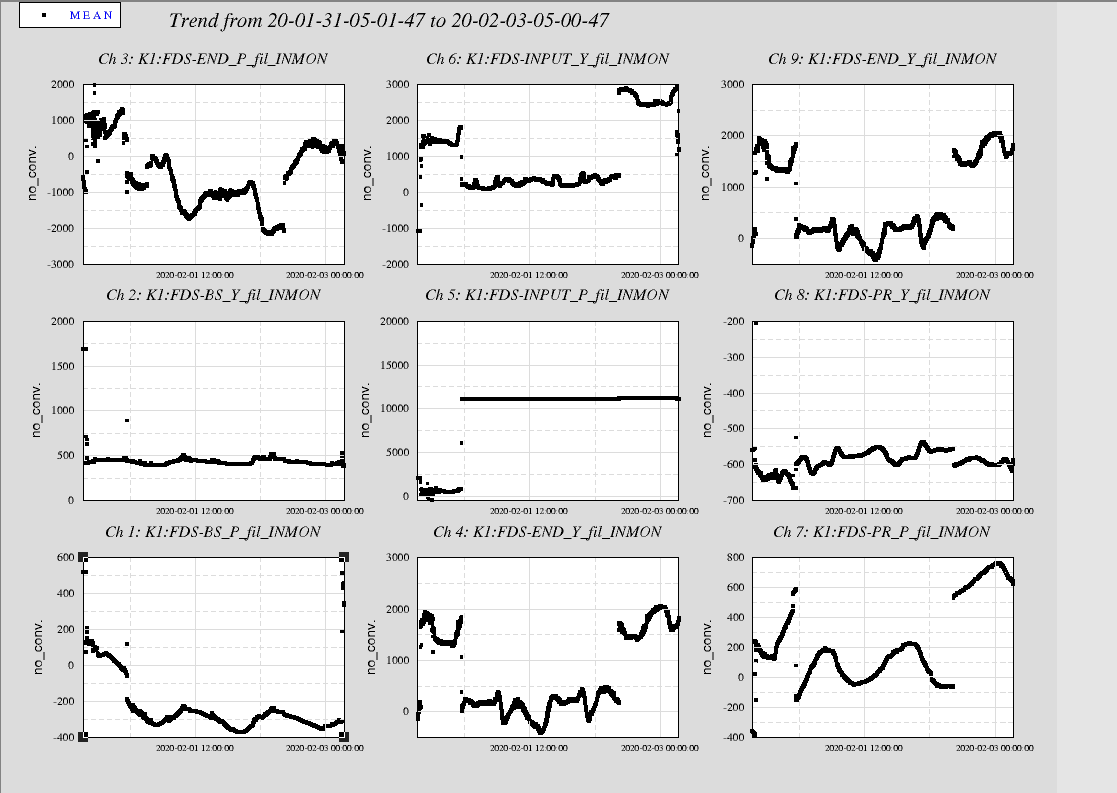
The strong earthquake of last friday night ( https://www.jma.go.jp/en/quake/20200131171237393-01020757.html) moved INPUT pitch too much and we could not recover with local controls.
So we used picomotors. Almost all the suspensions show a jump. See attached plot. Anyway the cavity has been realigned and looks more stable than usual.
What I did
- Modified the beam path of TEM00
- Measured the beam profile of TEM00 mode
- Adjusted the polarization of TEM00
- Started the installation of stage inside the chamber
Modification of optical path
As I replaced some screws before, I had to modify the beam path of TEM00 mode a little bit.
I aligned the EOM and lens after that in order to inject the beam into Faraday Isolator.
Measurement of TEM00 beam profile
After aligned the beam, I measured the beam profile of TEM00 which will be used for mode matching.
The result will be shown tomorrow.
Adjustment of polarization
Then I re-installed the Faraday isolator which is used for picking off the reflected beam for PDH locking.
So far, the polarization of TEM00 was adjusted to P-pol which is not appropriate one.
So I changed the polarization of TEM00 from P-pol to S-pol.
Now that TEM00 beam has S-pol.
HOMs' beam have P-pol.
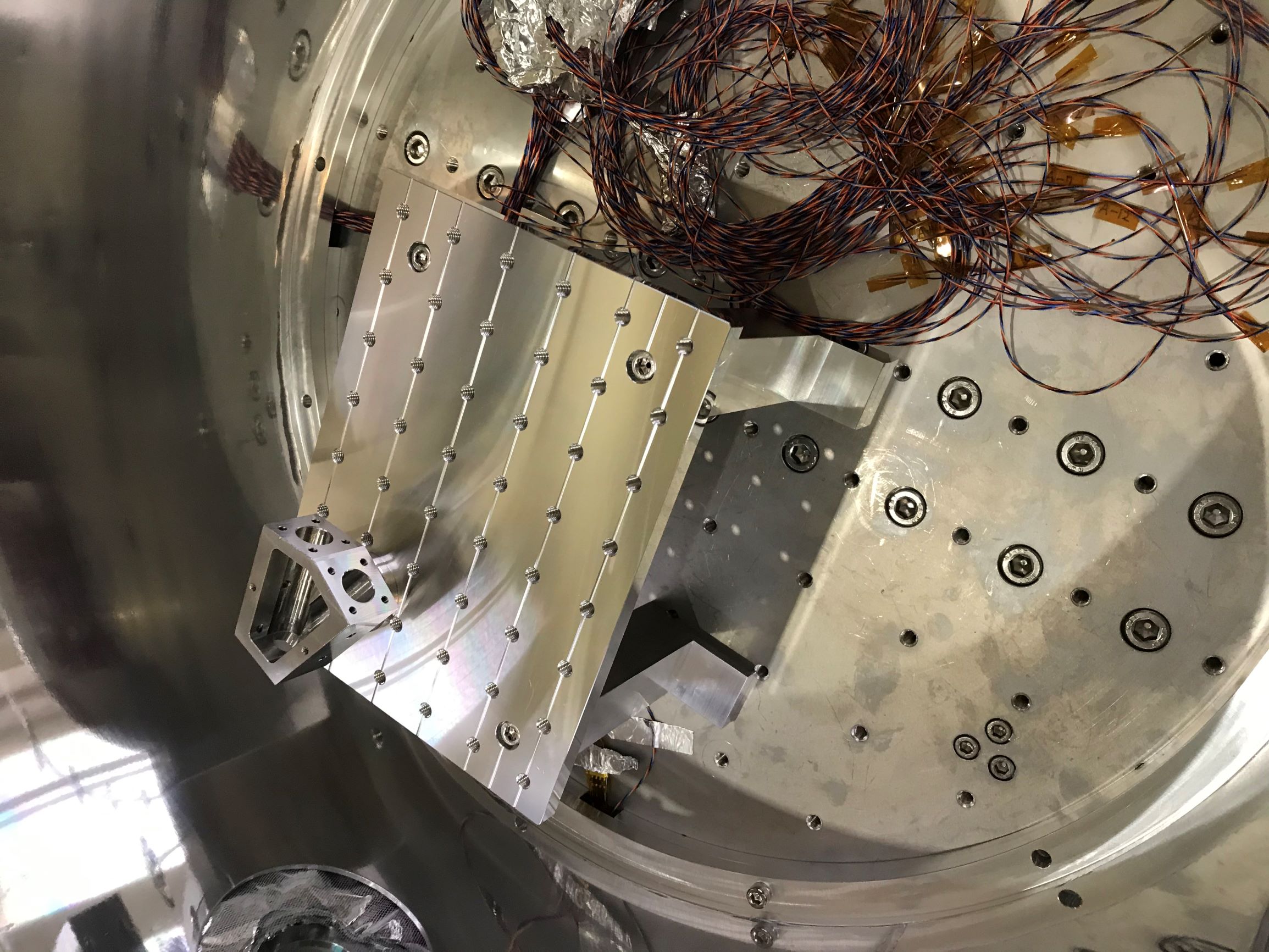
Installation of stage
As the beam height from the table of cryostat chamber is too high (about 160 mm), I designed the stage for compensation.
Since some parts were delivered, I started the installation of this stage as shown in attached picture.
Next step
- Modify the layout where close to the chamber
- Assemble the folded cavity
Actually, I think those results are not correct.
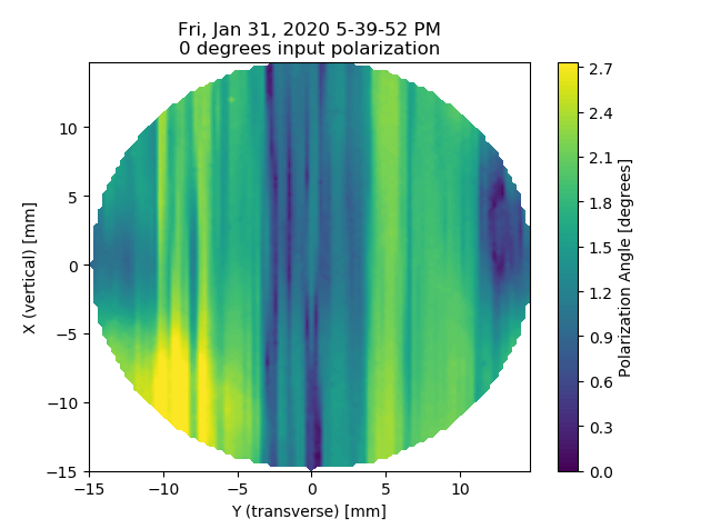
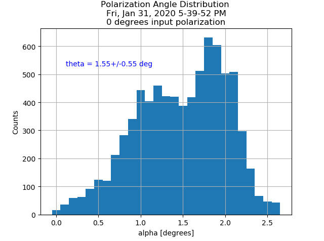
I re-calculated the S-pol map and got a much smoother distribution with those stripes being vanished almost completely.
As for P-pol, the map-data are unfortunately not reliable as the lock-in's sensitivity wasn't set correctly resulting in saturation on many occasions.
Pengbo, Simon
I changed the HWP holder for the input-polarization control to a motorized one. Now, we have full remote control of the measurements once the system is set up.
However, I noticed that with two motorized stages, the software to control both stages sometimes seems to be a bit slow in responding or does not respond at all (maybe due to the USB-hub?). Apparently, loading the controllers one by one helps and also running a short diagnostics seems to have some effect.
Also attached is the S-pol map (now corrected) from last week Thursday.
Compared with the former results (see elog 1807), we now see a significat reduction in abundance and strength of the vertical stripes. Our initial assumption that those are a result of polarization instability seems to be correct. Althought they are not fully removed, the system with the FI produces now much more presentable results.
Currently, the P-pol measurements are done again with both HWPs motorized.
Aritomi, Eleonora, Yuhang
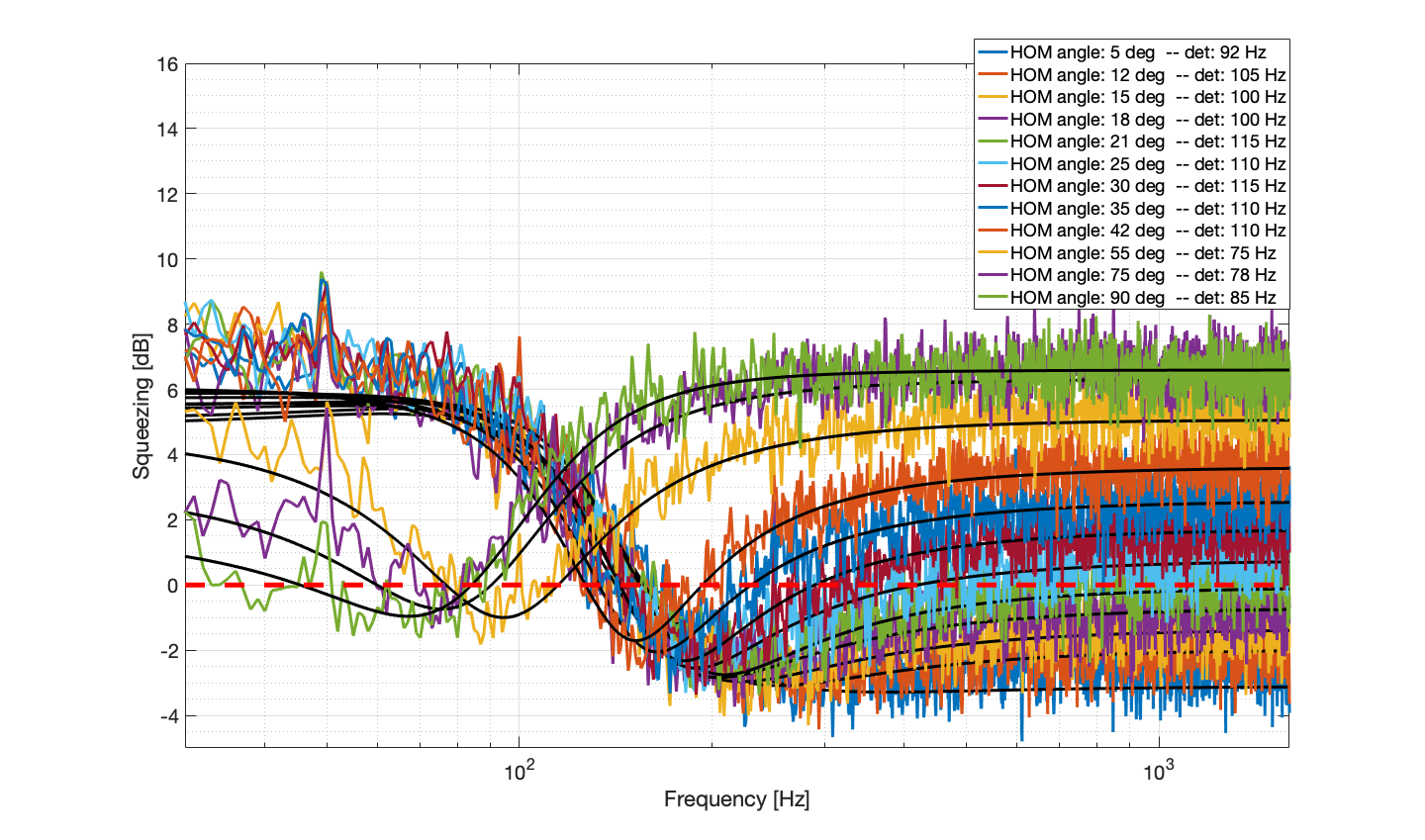
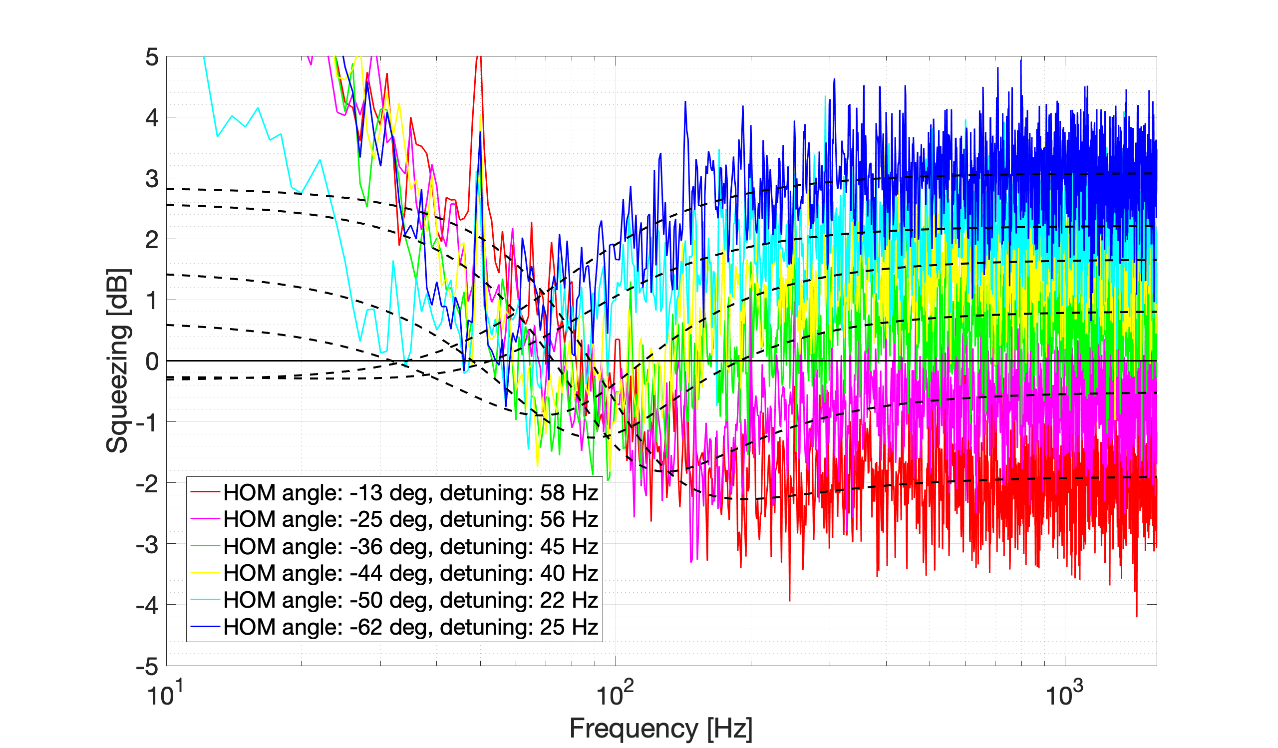
We tried to measure FDS with correct detuning (this time produced squeezing level is only 5 dB and we are thinking temperature may be responsible for this change). However, low frequency part is dominated by back scattering as expected.
Good thing is that the rotation part of the curve is still visible from the noise curve. We are also thinking to increase the average times to further reduce the spectrum curve thickness, so that the rotation part can be more clear. It's also better to analyze the data as soon as we take it and if it's not correct detuning, we should tune the detuning and take the data again.
Simon, Pengbo
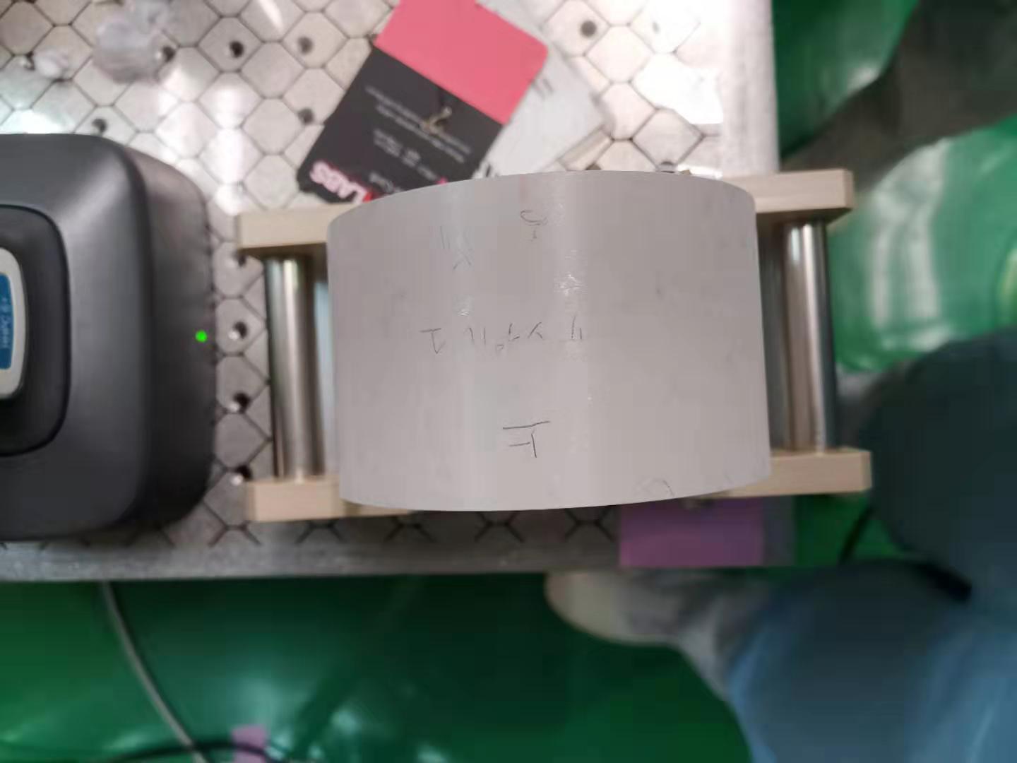
We reconfigured the polarization system and did a test measurement on tama-size #1.It was place on the mount with the mark point to the top.
As can be seen from the result, both the maps show a smaller offset compared with the result measured before.
Also we can see some structure pattern from the bottom left corner to the top right corner.
Actually, I think those results are not correct.
I re-calculated the S-pol map and got a much smoother distribution with those stripes being vanished almost completely.
As for P-pol, the map-data are unfortunately not reliable as the lock-in's sensitivity wasn't set correctly resulting in saturation on many occasions.
In the last FDS measurement, average detuning is 119.6 Hz and the standard deviation is 11.6 Hz. This is kind of consistent with the measurement of locking accuracy which is 6.4 Hz.
I modified the pitch damping filter for the INPUT mirror to reduce the 9 Hz peak that was showing up in the IR lock accuracy plot.
New filter is ACdamp3 and seems to work better.
To reduce the effect of locking accuracy, I reduced the pump green power. First I reduced green power from 26.7mW to 20mW by changing MZ offset, but I couldn't lock GRMC and MZ.
Then I put OD0.2 after GRMC and green power reduced from 26.7mW to 18 mW.
OPO temperature and p pol PLL frequency are 7.173kOhm and 220MHz with 18mW green power.
[Aritomi, Yuhang, Eleonora, Matteo]
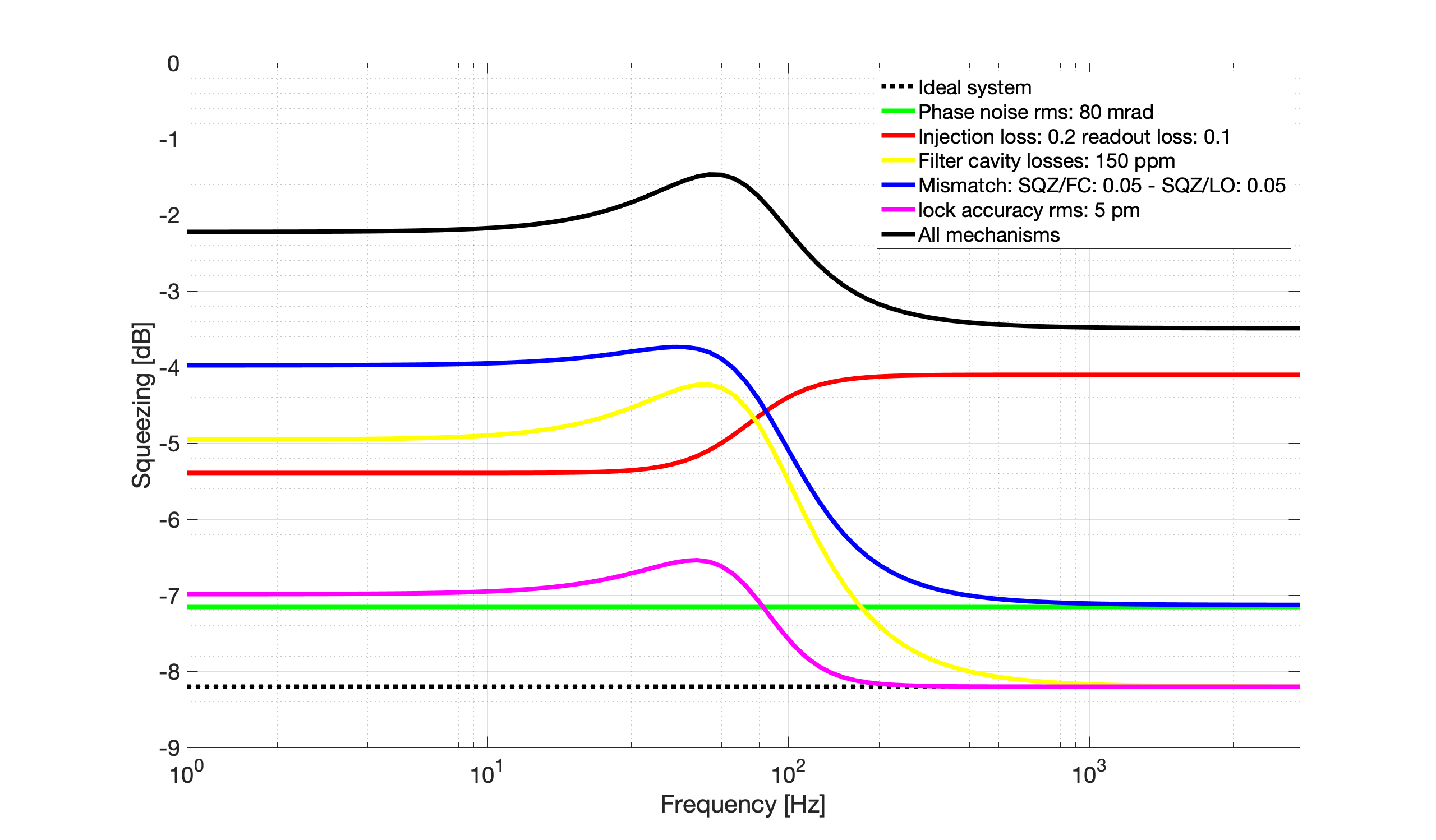
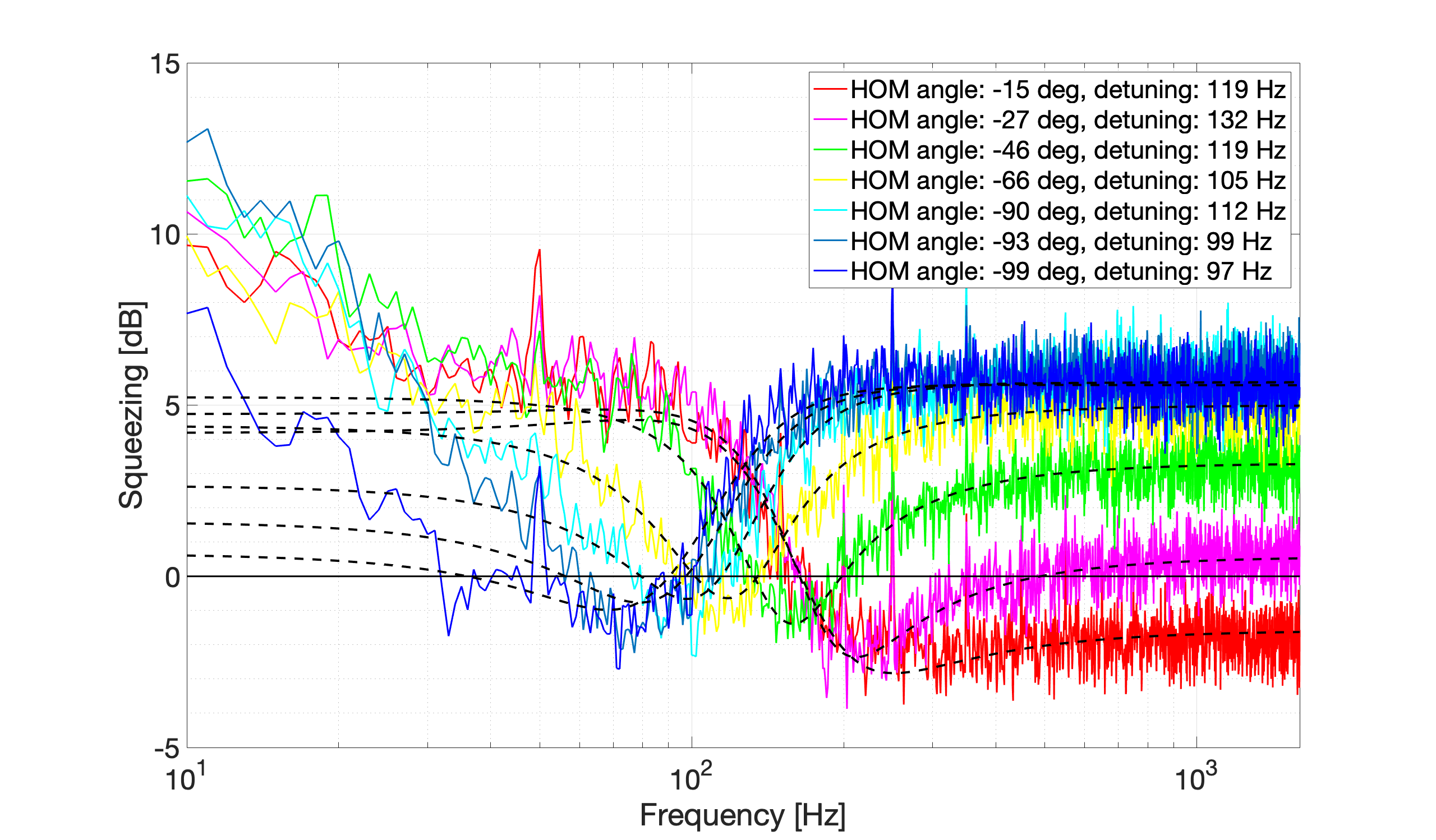
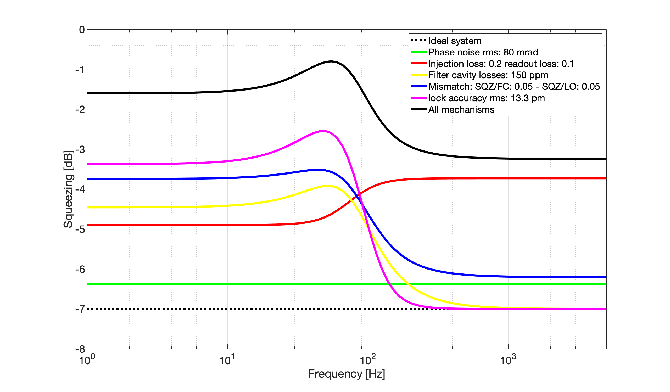
By reducing green pump power from 26.7mW to 18mW, we managed to reproduce the last Friday's FDS measurement. The detuning is around 100-130Hz. It seems that squeezing level at low frequency is still limited by locking accuracy.
The parameters are as follows.
sqz_dB = 7; % produced SQZ
L_rt = 150e-6; % FC losses
L_inj = 0.20; % Injection losses
L_ro = 0.11; % Readout losses
A0 = 0.05; % Squeezed field/filter cavity mode mismatch losses
C0 = 0.05; % Squeezed field/local oscillator mode mismatch losses
ERR_L = 13.3e-12; % Lock accuracy [m]
ERR_csi = 80e-3; % Phase noise [rad]
Strong 50 Hz showed up again in the end oplev signals. We went to check and tweeked a bit the cables but in all the other configurations that we tried it was worse.
I put a digital notch at 50 Hz in the optical lever signals.
We found the rapeauto was set to 1/f instead of 1/f^4, we put it back to 1/f^4 and adjust the gain:
INPUT ATTENUATON : 1.9
PIEZO GAIN: 4
We measured open loop TF: UFG = 20 kHz, phase margin: 55deg.
It didn't improve the stability problem we have on cavity transmission.
When IR alignment is good, IR trans is around 290 count for 220 uW of IR injection.
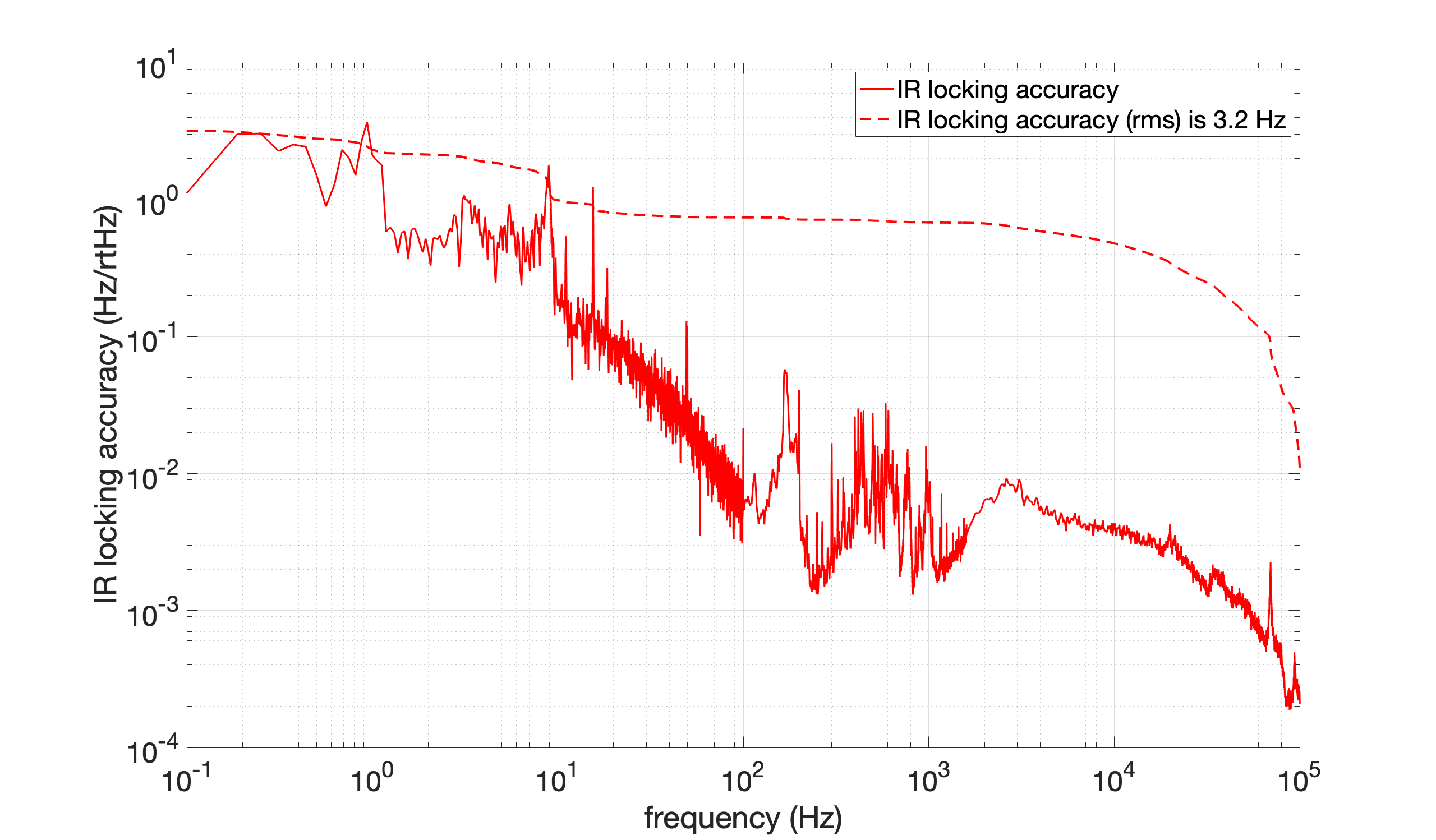
When we integrate IR error signal down to 1Hz, locking accuracy is 2.3 Hz.
When we integrate IR error signal down to 0.1Hz, locking accuracy becomes 3.2 Hz which corresponds to 3.4 pm.
[Aritomi, Yuhang, Raffaele, Matteo, Eleonora]
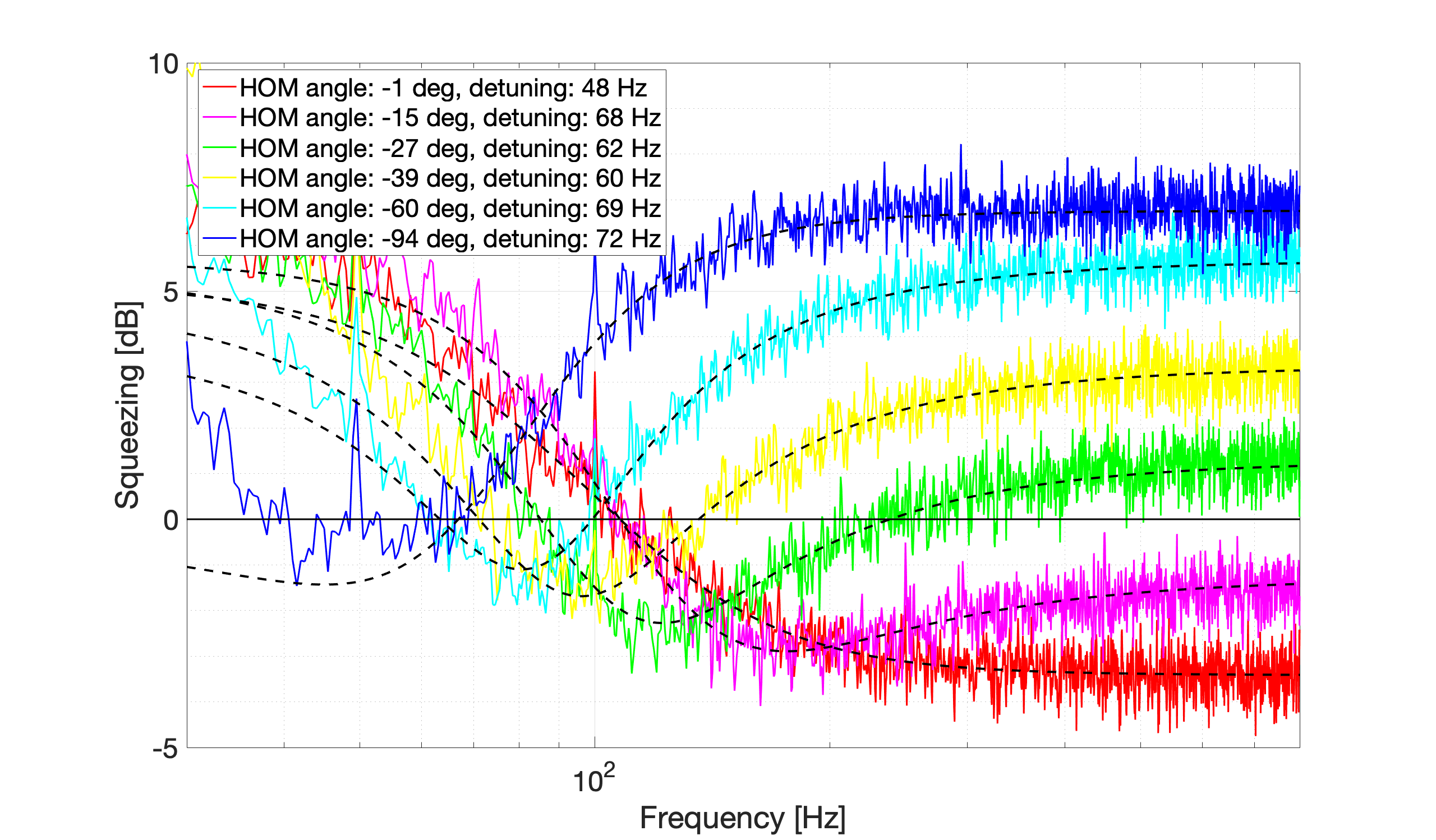
I did a quick fitting of the FDS measuremnt we did last friday (24/01).
We have about 1 dB of FDS sqz at low frequency and 3.5 dB at high frequency.
We see that at some point during the measurement the detuning changed from ~100 Hz to ~70 Hz.
Sqz degradation paramenters used for the fit: