NAOJ GW Elog Logbook 3.2

Today, just after I align GR well (GR transmission is at the level of ~2550counts, with 12.28mW GR injected to FC) to FC, I checked BAB in FC transmission and reflection.
For transmission, the level is 340counts. Then I measured the injected power into FC, it was 0.333mW. By comparing the standard number we recored in WIKI, transmission is misaligned by ~20%. ((340-100)/(392-100)=82%)
For reflection, roughly also 20% is misaligned. (check the last attached picture for reflection in to AMC)
Last time we aligned BAB to FC is this Monday.
I tried to align FC again and the second time, TRA got misalign 60% while reflection is also roughly 20%. So reflection seems to be less sensitive to alignment.
I have updated the RT model and medm screen.
- The WD system is added.
- The commish message is also added and that can be seen from the sitemap.adl. Here, you can leave the comment when you do not want someone else to touch the FC remotely.
Shoda and Yuhang
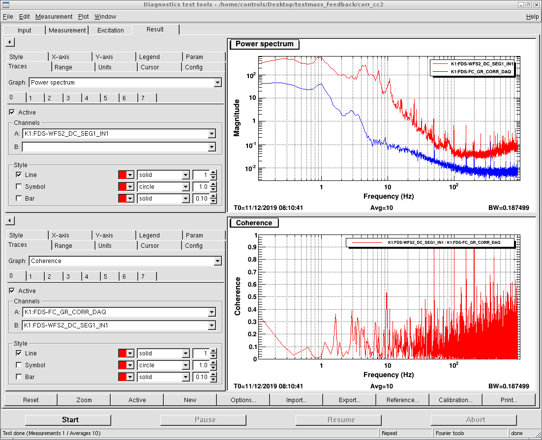
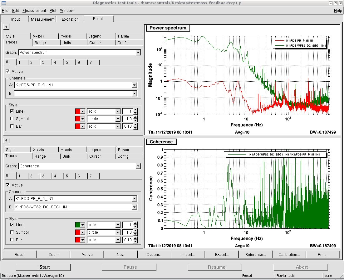
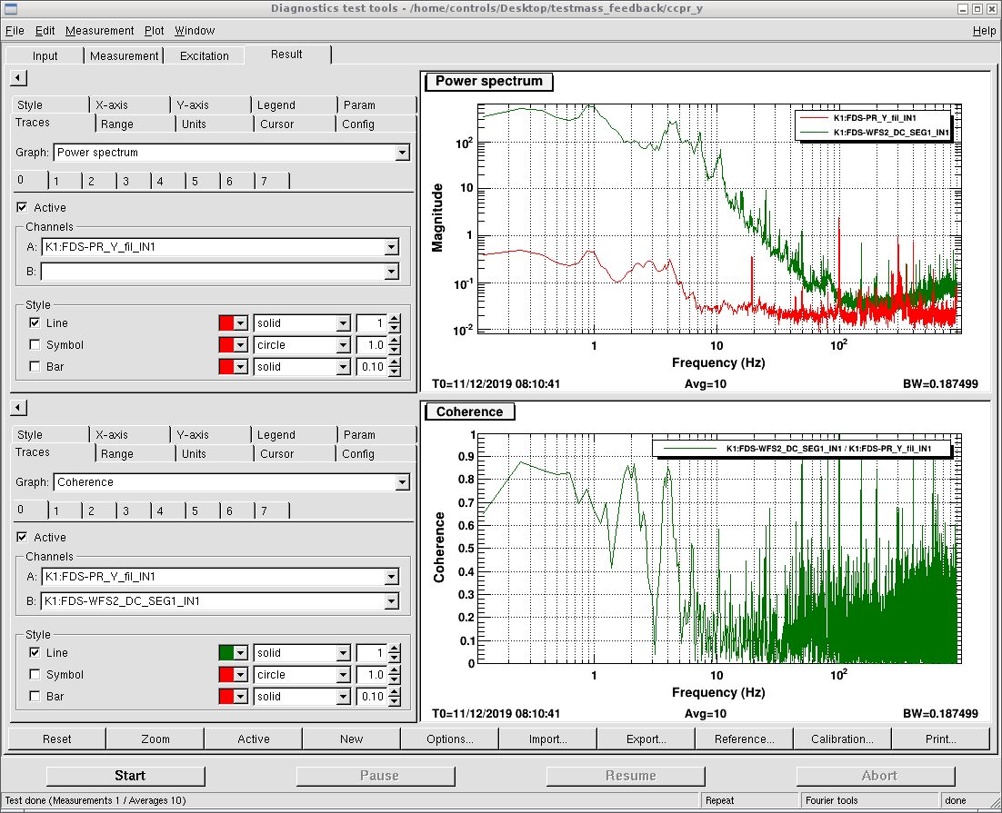
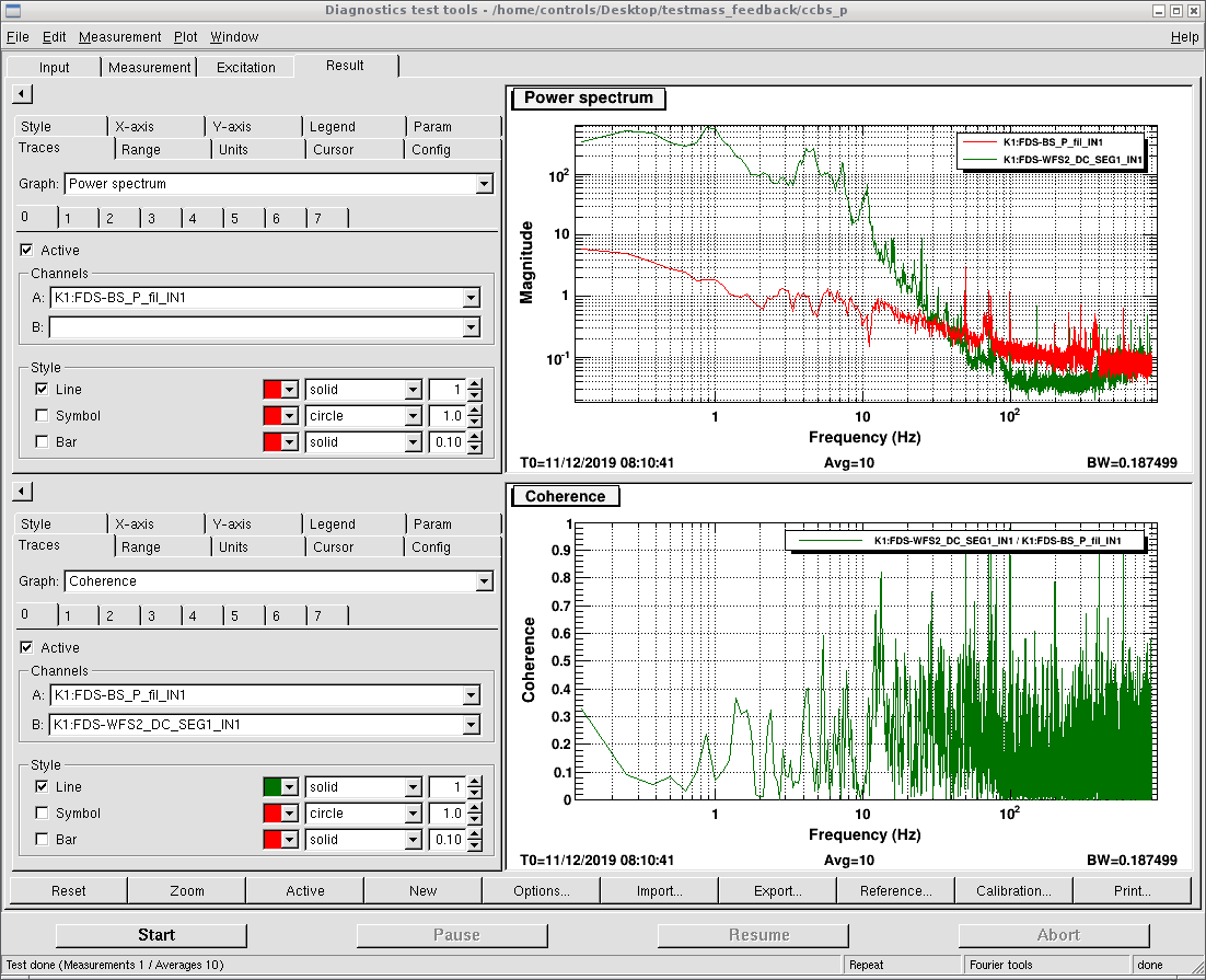
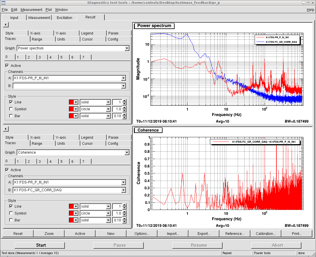
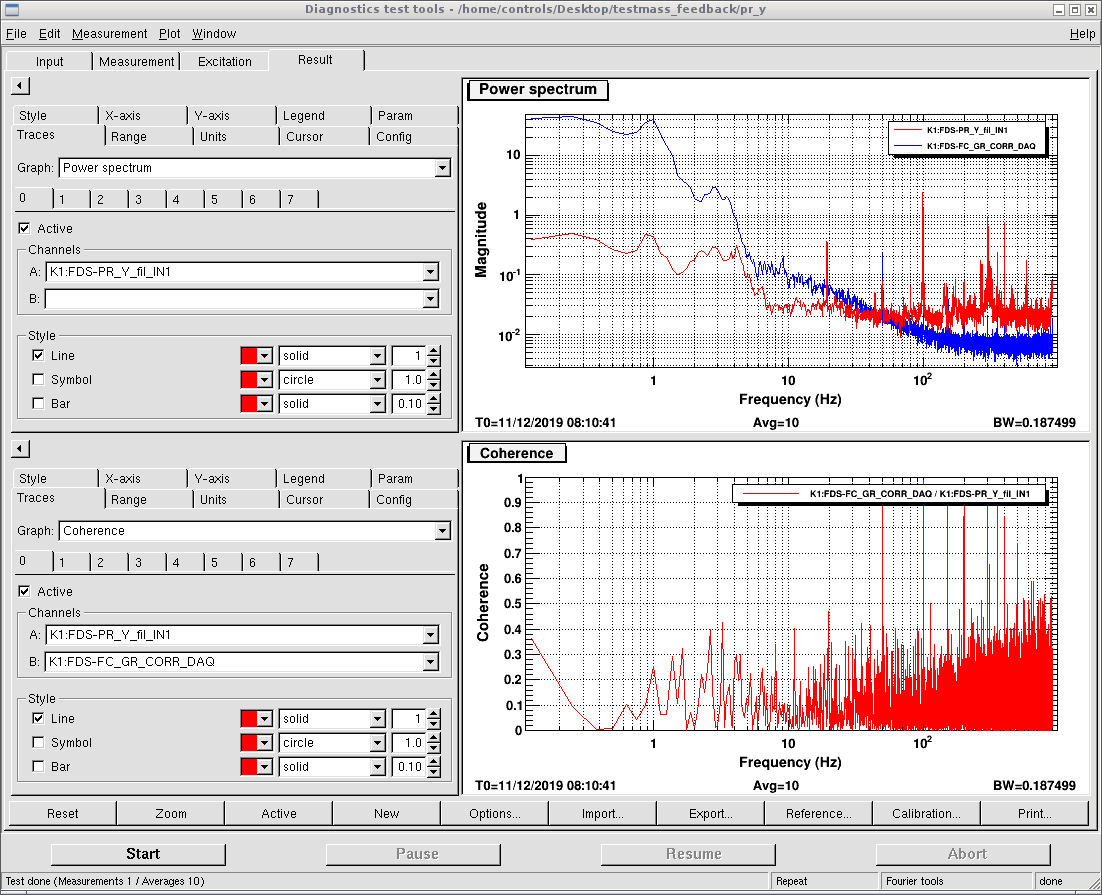
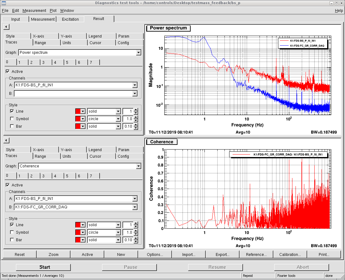
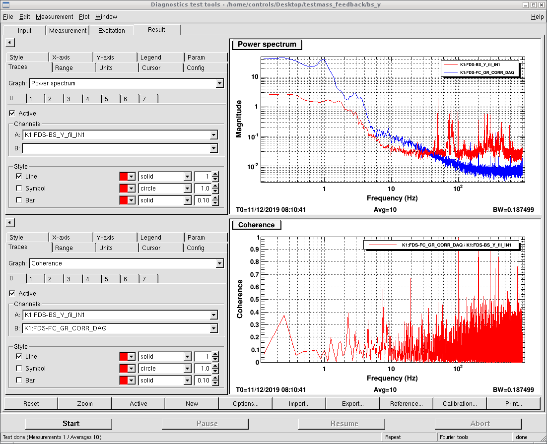
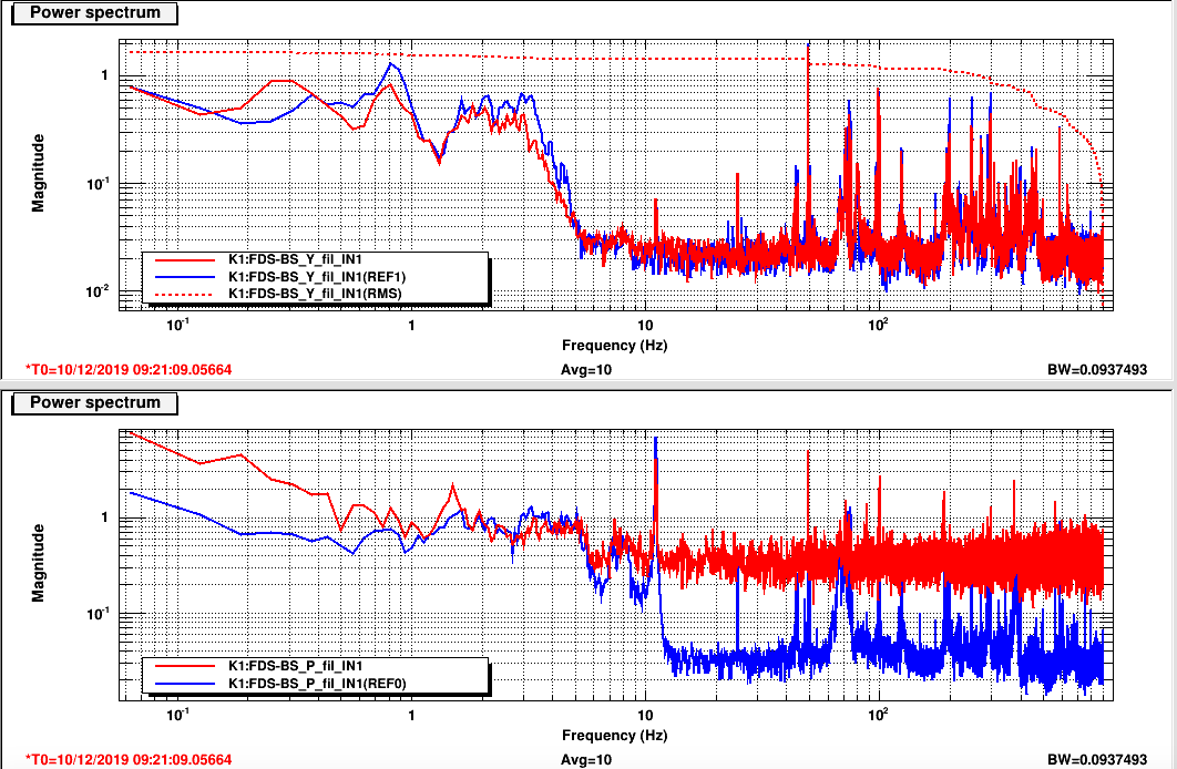
We checked the coherence between each suspended mirror and CC2 correction signal.
The coherence below 0.5 is not mentions in the following form, check detail in the attached pictures.
|
|
pitch |
yaw |
|
PR |
0.8 coherence around 4Hz |
0.9 coherence from 2 to 4Hz |
|
BS |
0.8 coherence @12Hz |
0.6 coherence @3 and 4Hz |
|
Input |
0.55 coherence from 3 to 10Hz |
0.9 coherence from 2 to 3Hz |
|
End |
no |
no |

Shoda and Yuhang
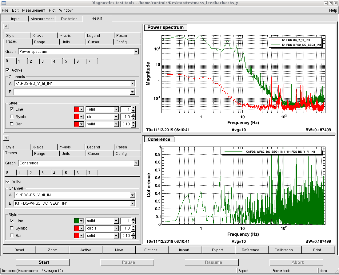
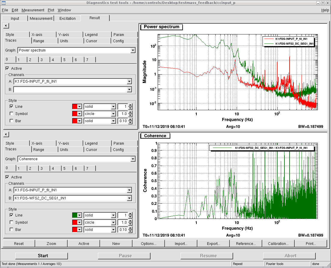
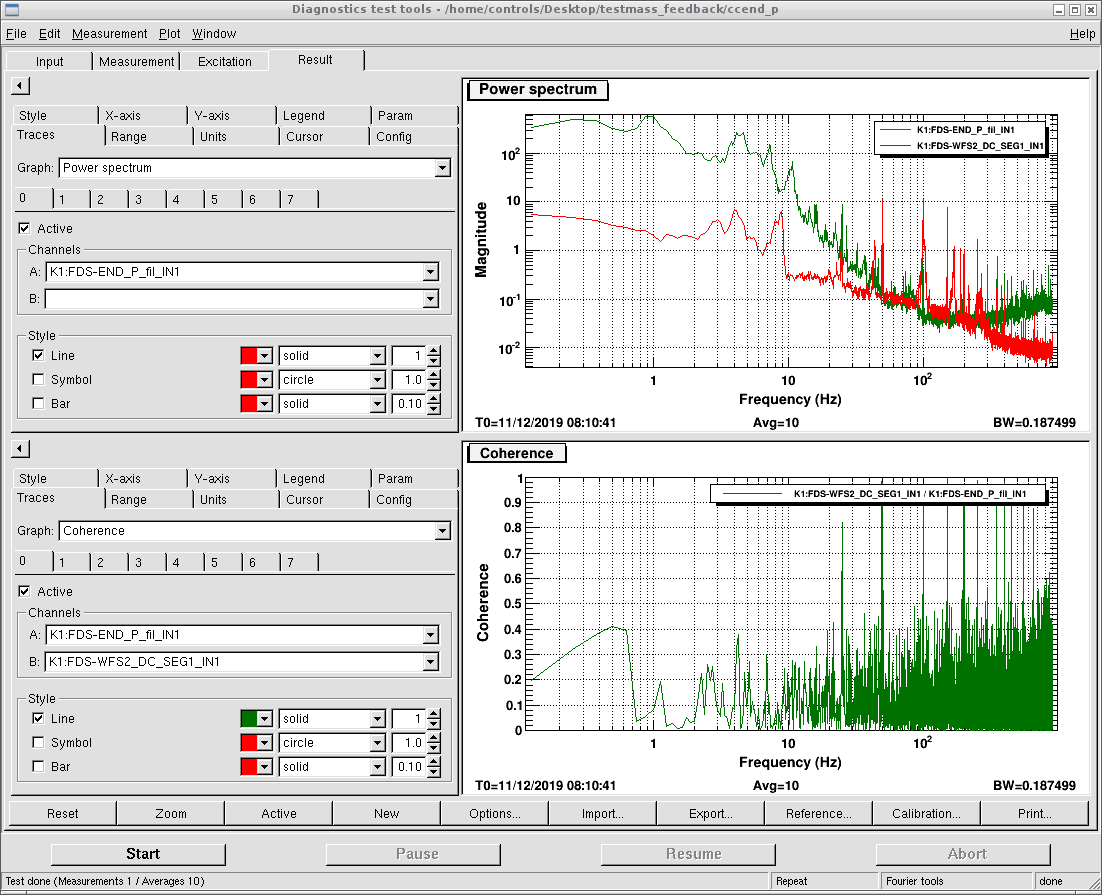
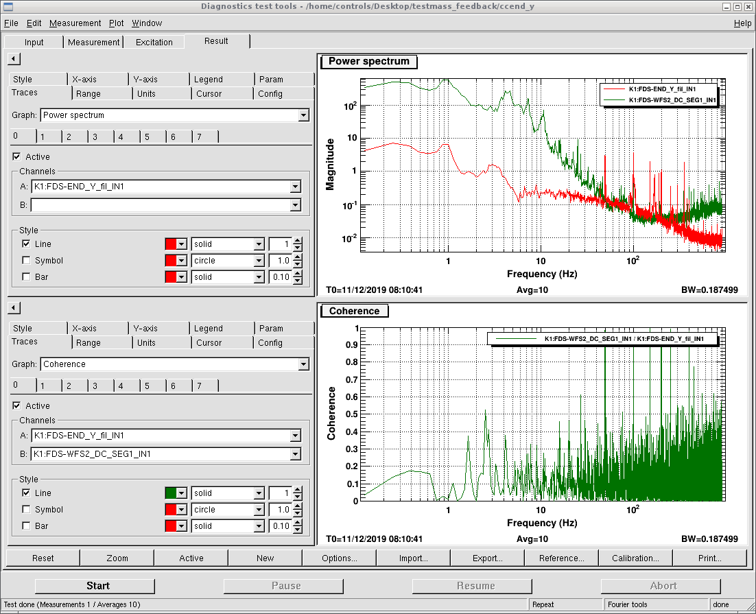
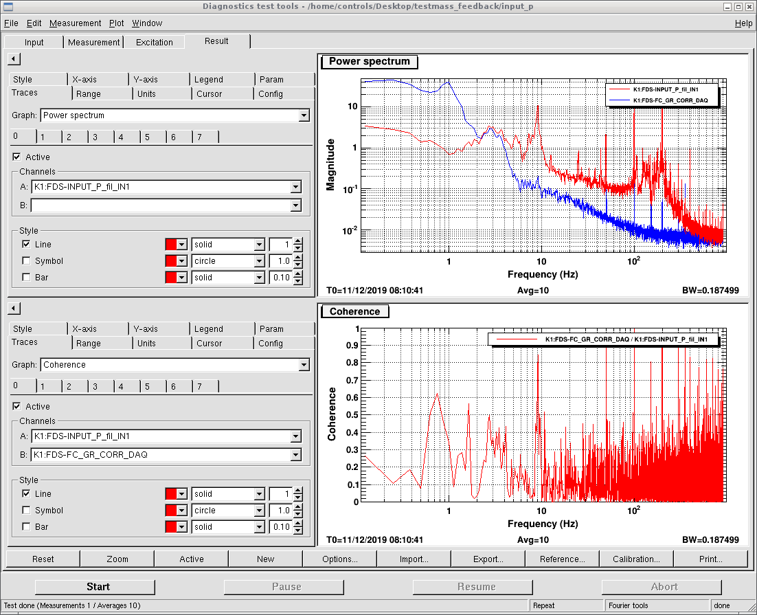
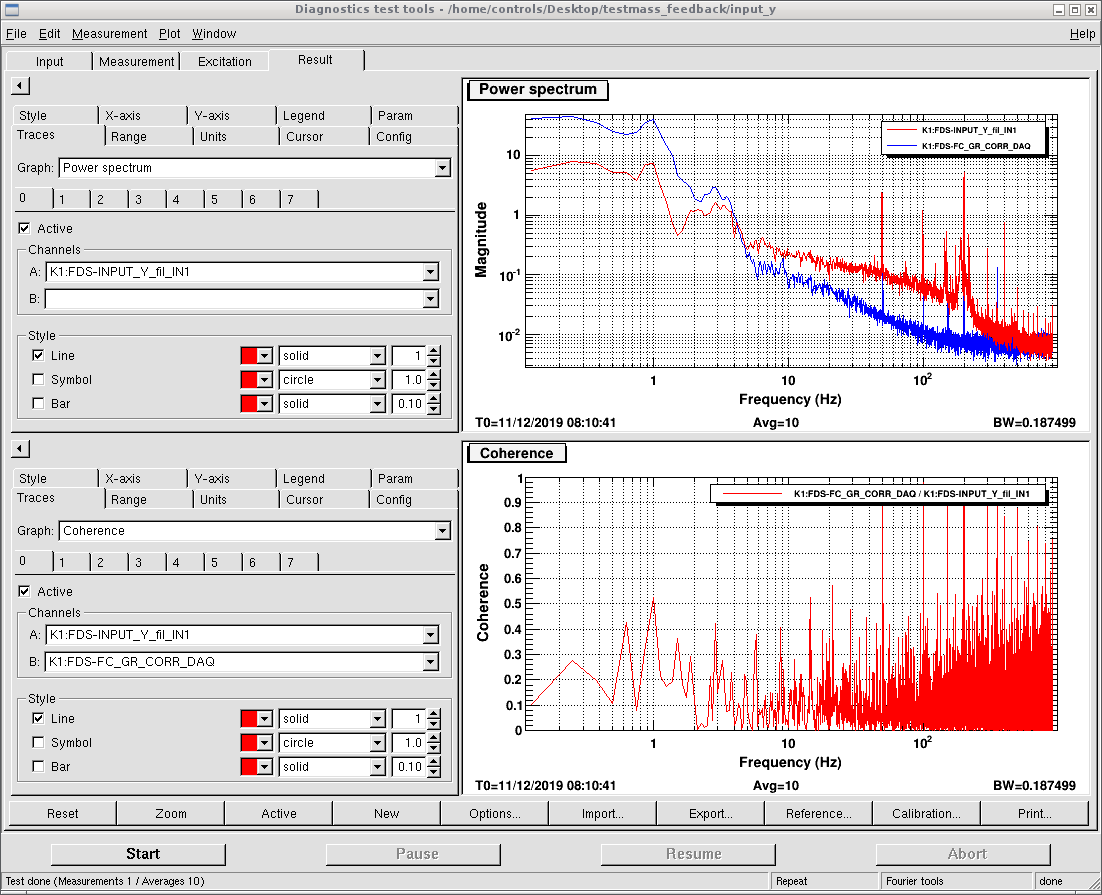
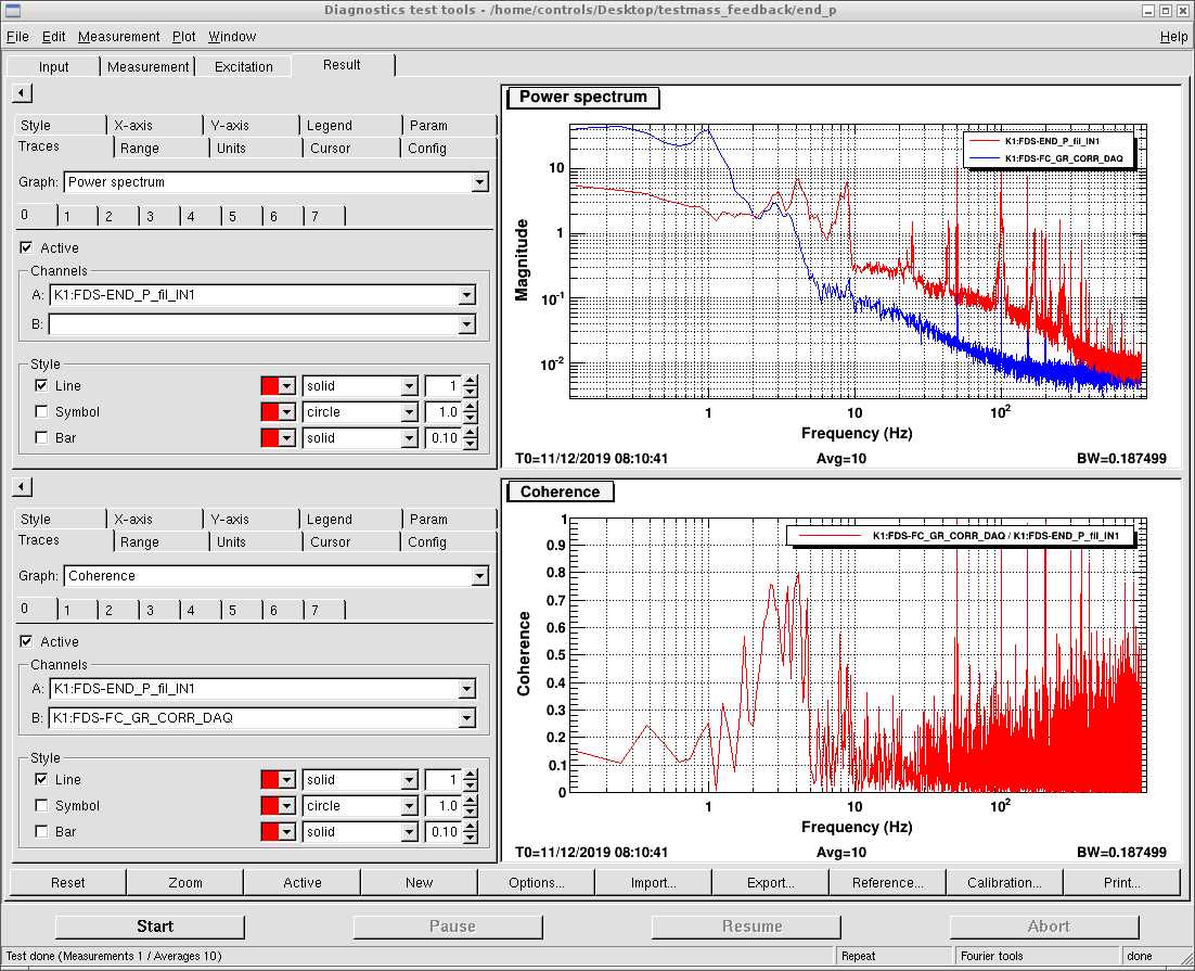
We checked the coherence between each suspended mirrors oplev signal and correction signal to FC length. The situation is summarized as follows.
The coherence below 0.5 is not mentioned. For the detail, please check the attached figures.
|
|
pitch |
yaw |
|
PR |
almost no coherence |
almost no coherence |
|
BS |
almost no coherence |
almost no coherence |
|
Input |
coherence of 0.8 @ 9Hz |
almost no coherence |
|
End |
around 2~5Hz coherence of 0.8 |
around 2~4Hz coherence of 0.6 |

Yaochin and Yuhang
Since last week we had again the problem of filter cavity. We saw filter cavity transmission varied from 2000 counts to 3000 counts. In the end, we found out actually we are not operating SHG in the optimal temperature. Also, we had a temperature change due to the change of air-conditioner mode, so it varied.
After everything settles down, we fixed again the setting of the filter cavity lock loop.
|
Attenuation |
2.9 |
|
Gain |
2.0 |
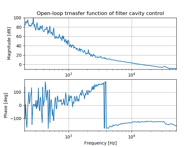
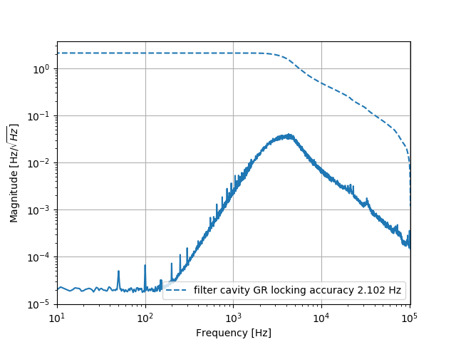
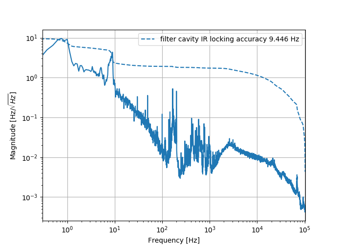
Then we measured the open-loop transfer function again. Also, GR locking accuracy and IR locking accuracy. Especially this time we measured more accurately the low-frequency part of it. And compared with the measurement we did more one year ago(elog 690), the high-frequency part is the same while the low-frequency part is quite different. We should consider more why we have this big difference in IR error signal now.
We should also measure coherence between IR error signal and each oplev spectrum.
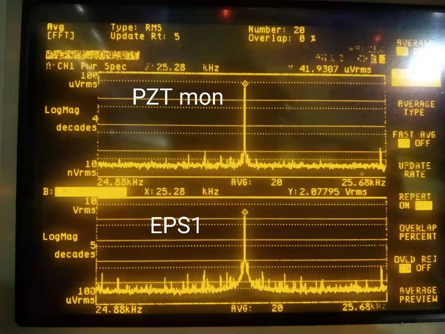
As pointed out in the last FC meeting, the error signal for green and infrared around 10kHz is similar. This is actually strange for me. Due to the cavity pole for infrared and green has a factor around 25 difference. Above their pole frequency, the green error signal should be around 25 times larger than infrared.
However, I checked several times this entry and compared with elog642, I couldn't find what is wrong. I will try to measure it again.
As pointed out by Aritomi-san, the formula used to calibrate the measurement had some problem (check entry642). After correcting that, the measurement result becomes reasonable.
I am sorry that what I wrote is wrong. The additional loss is 1-visibility**2. I think it is very clear for us that the efficiency of homodyne is visibility**2. This is written in Henning's thesis.
Today, I assembled the third 80K shield window because the first one has some scars (around the edge of the mirrror though).
Therefore I decided to use two better ones for my experiment.
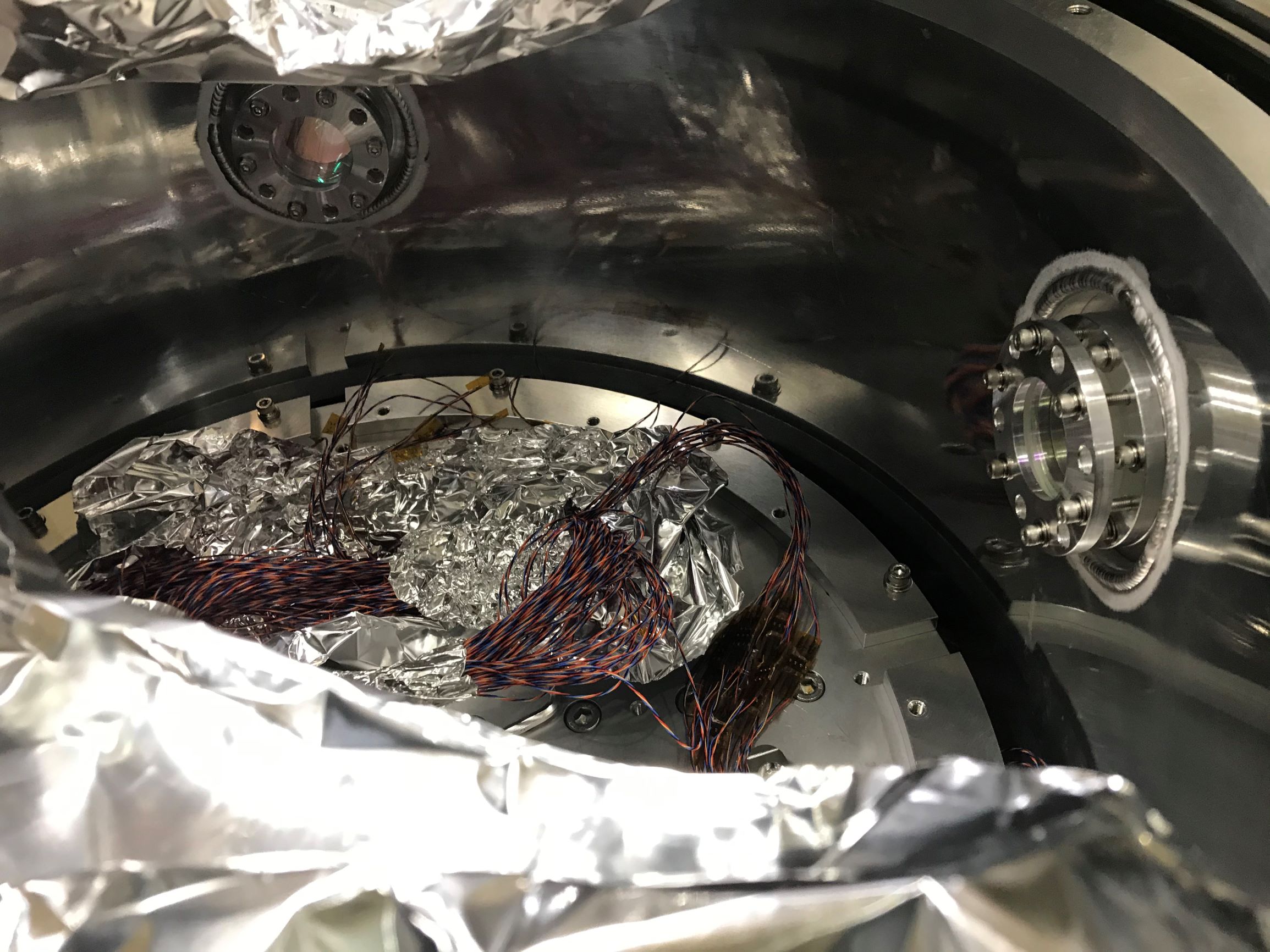
After assembling, I installed two 80K shield windows on the adapters where they are attached at input and output ports as attached picture.
When I was installing, I used indium wire between the mirror holders and adapters in order to improve heat conduction.
[Next Step]
- Cabling inside the chamber
- Install 4K shield
- Cooling test
I think it's better to measure visibility directly.
>> We also considered the loss introduced by non-optimal visibility is the square of (1-visibility).
This seems not correct. This is how I calculated additional loss in entry 1587.
1. Measure voltage of LO, BAB (HWP 0deg), DC offset, visibility (HWP 0deg)
2. Rotate HWP and measure maximum and minimum of visibility
3. Solve the following equation in terms of V_BAB
(V_max-V_min)/(V_max+V_min-2*V_DC)/(2*sqrt((V_LO-V_DC)*(V_BAB-V_DC))/(V_LO+V_BAB-2*V_DC)) == visibility (HWP 0deg)
4. Additional loss should be 1-V_BAB/V_BAB (HWP 0deg)
Simon
Yesterday, while doing the reflection and transmission measurements, I briefly checked the existence of some ghost-beams of the examined polarizers.
It seems so far, that there are ghost beams but I could see them only for P-pol at large AoI (>65 deg).
For S-pol, I couldn't recognize any second order reflection...
Investigation is to be continued.
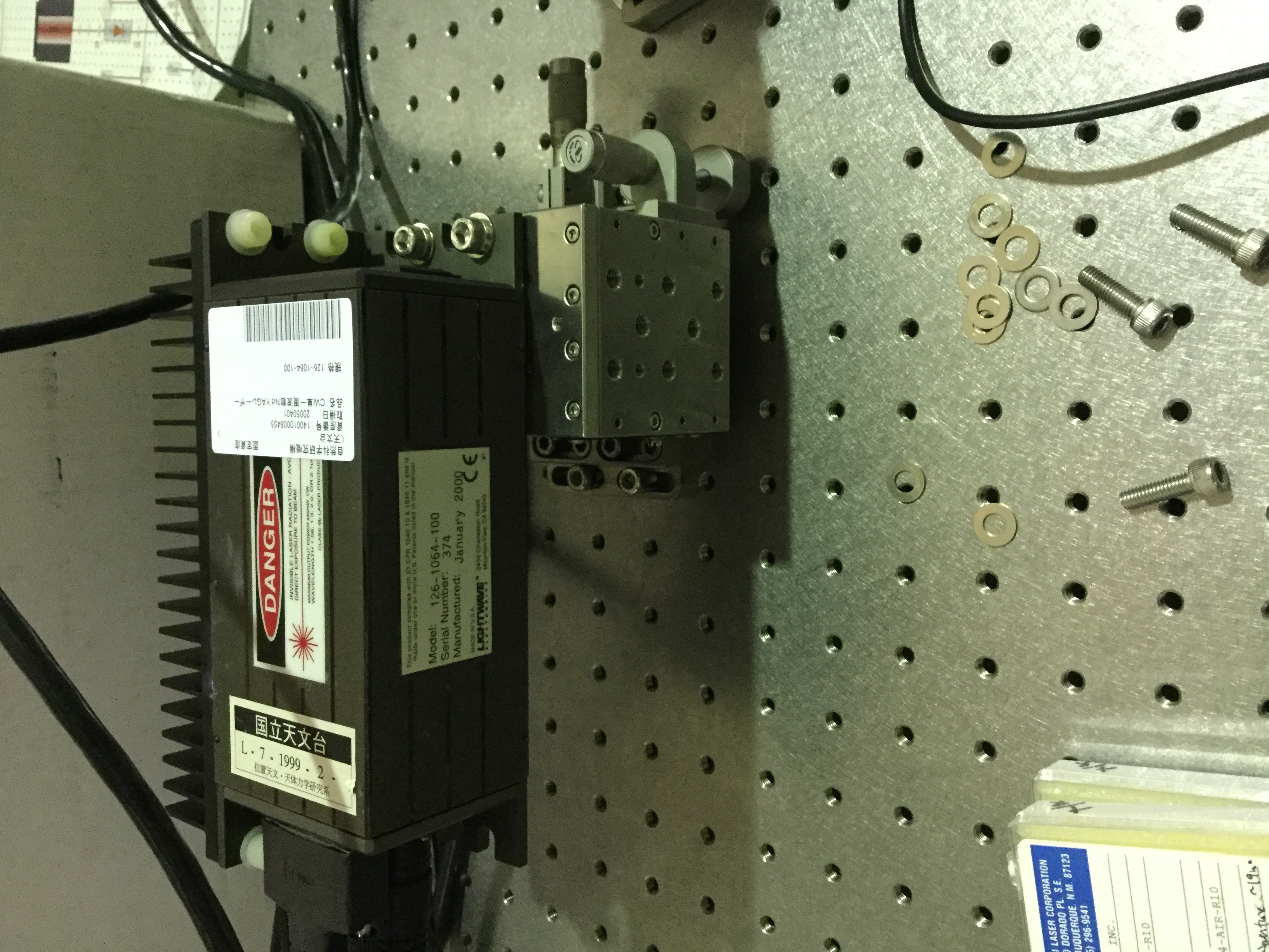
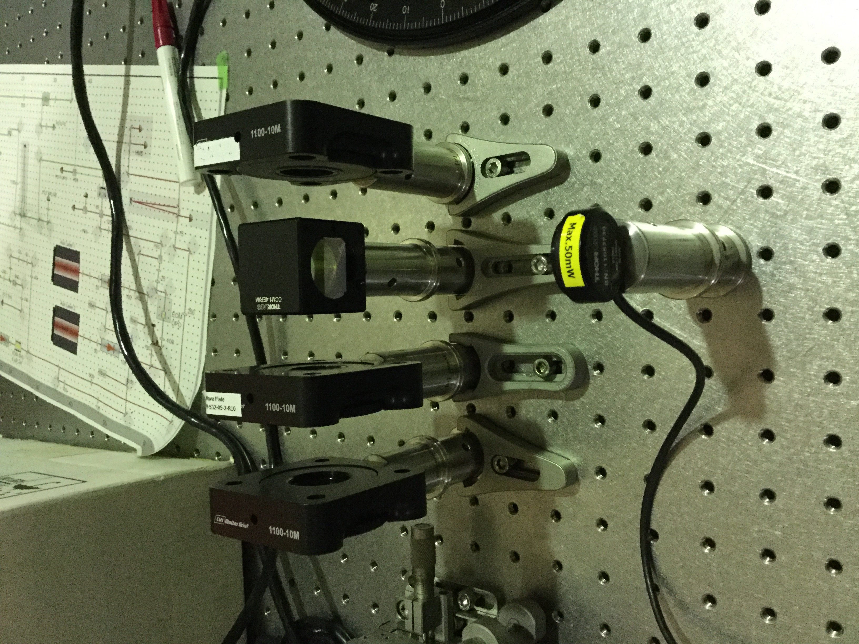
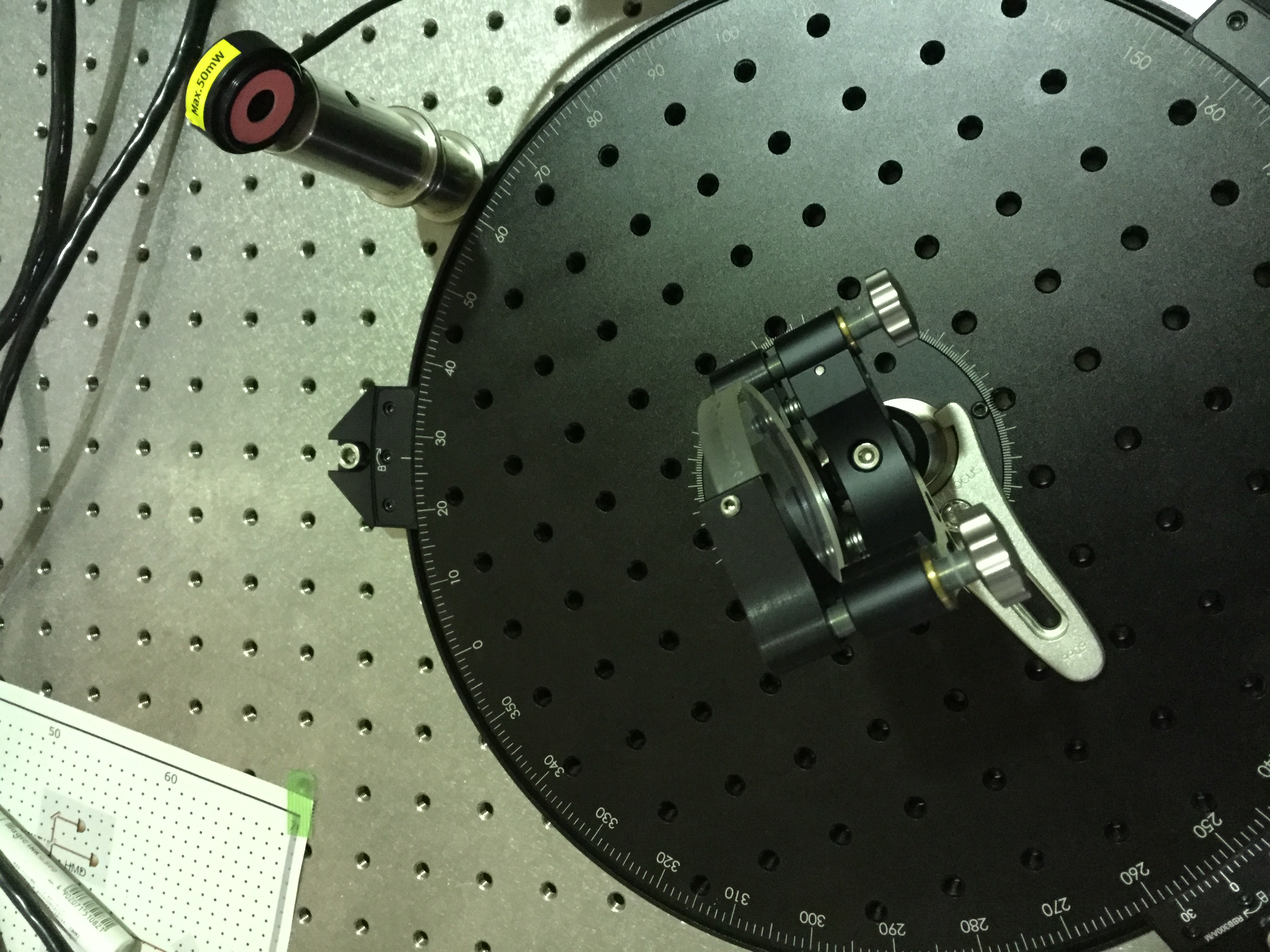
Simon
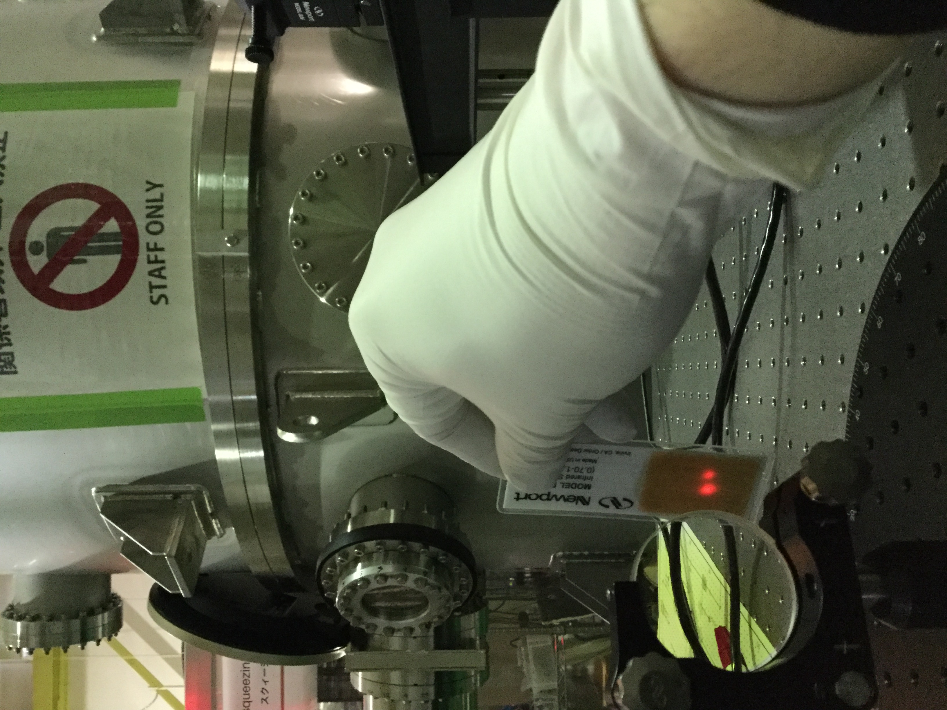
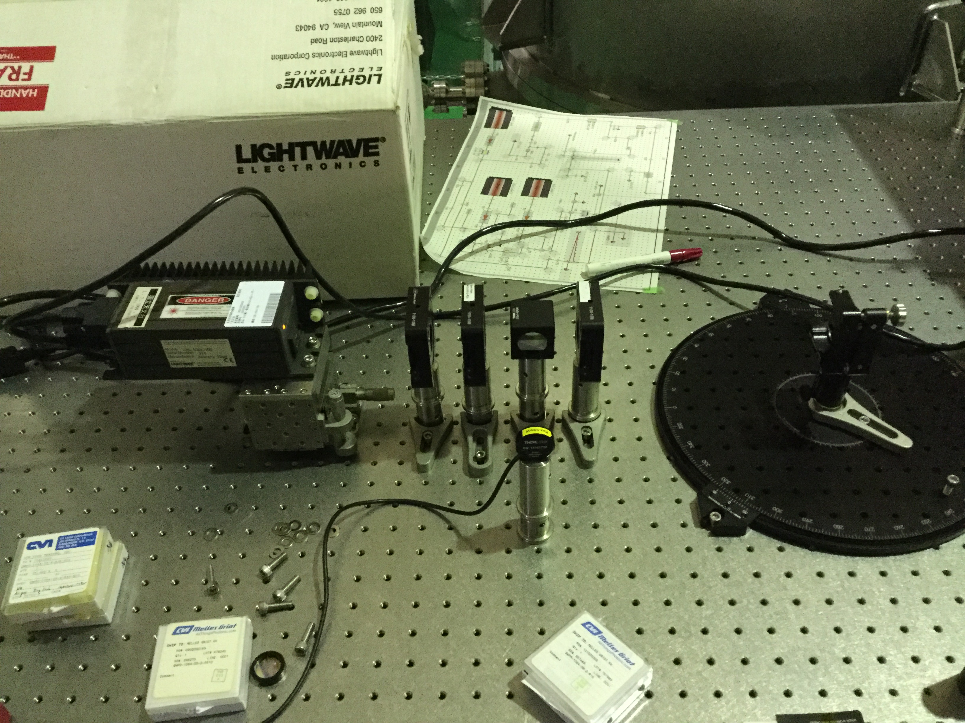
Note: The measurement bench is open for anybody who wants to do some quick characterizations of samples
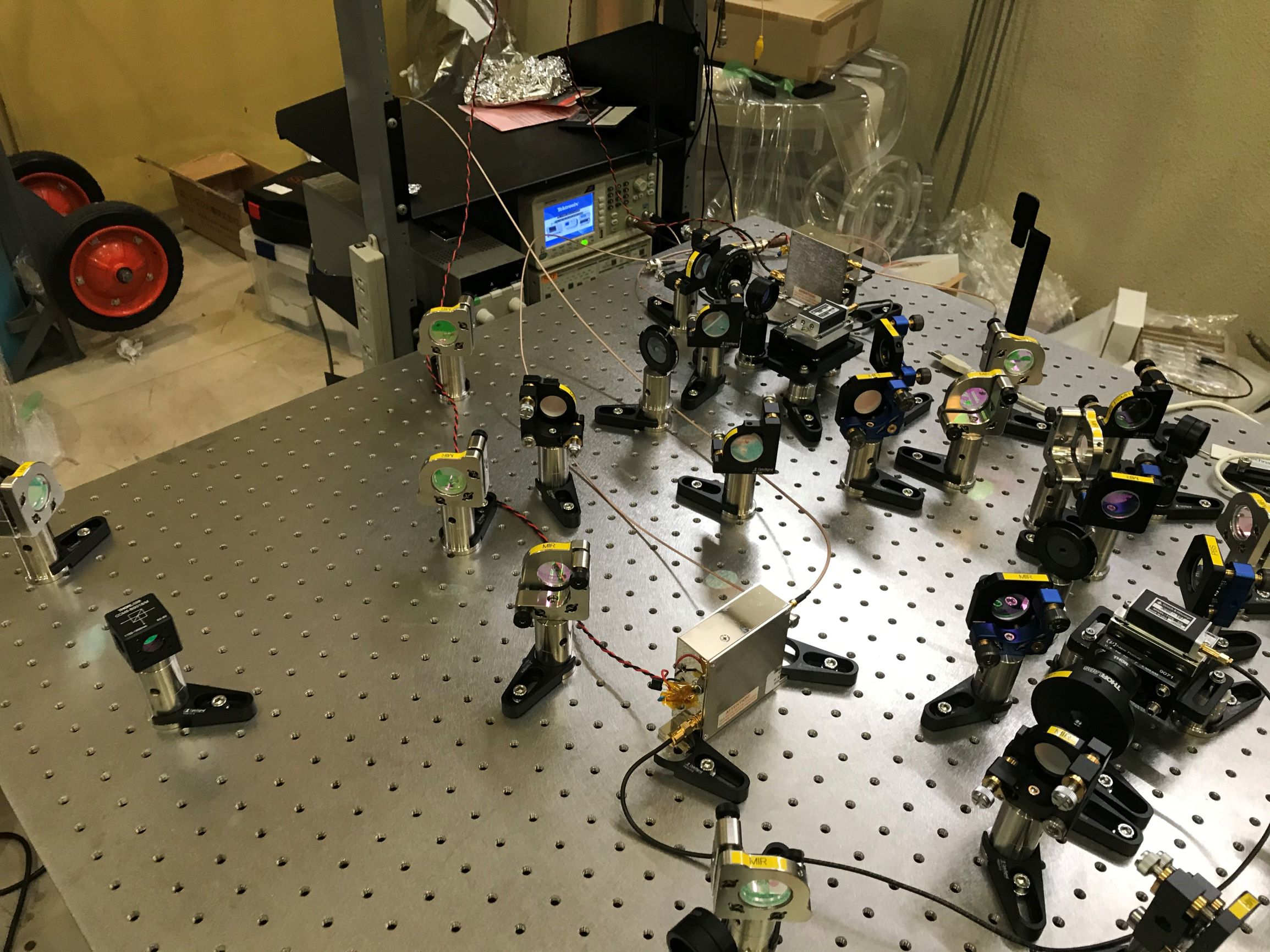
Please find attached also some photos of the setup right now.
Simon
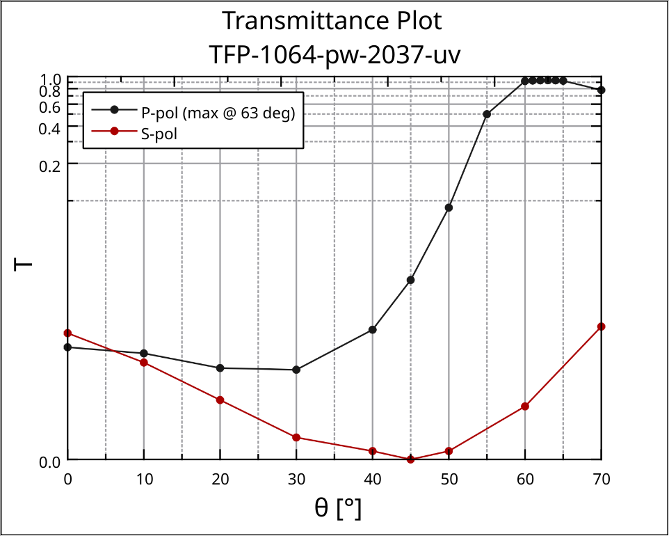
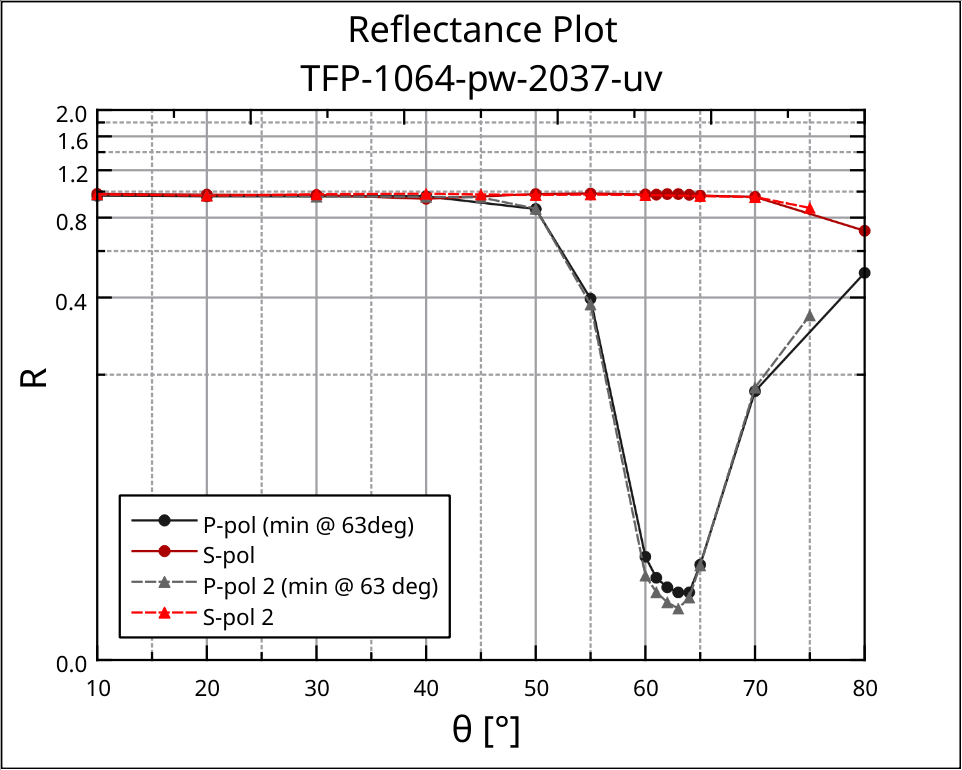
In addition to the measurements on Monday, I took the transmission data for both S and P polarization of the Brewster Polarizer. This is to further understand the type of coating that has been manufactured for it.
Attached is the respective graph.
As can be seen, in S-pol there is a distinct minimum at 45 degrees, while for the transmission in P-pol the minimum is at around 30 degrees with a maximum at 63 degrees AoI. This result correlates quite well with the reflection measurements.
Also, I characterized a second polarizer of the same type in terms of reflection and compared it with the previous one.
The reflection curves of both polarizers are almost identical and show the same location of the minimum in P-pol (~ 63 degrees).
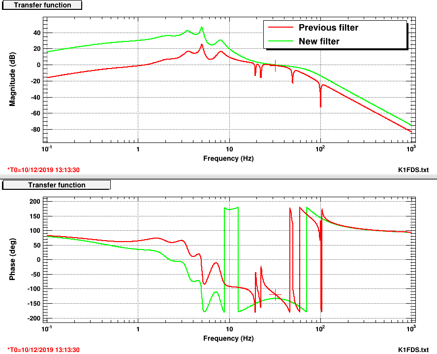
Attached is the designed OLTF of the previous and the new servoes on Dec 6th.

The phase mergin is about 40 deg. The difference of gain at above the UGF is about 10 dB.
Also, I have tried to look up the time the PR was resonating (at around 6/12/2019 6:00 UTC), but I could not find any DAQ signal for PR local damping loop.
Why don't we add some (if the storage allows)?
Yaochin and Yuhang
Since we did the optimization of the HWP angle for BAB. By this chance, we did again what Aritomi-san reported in elog1587.
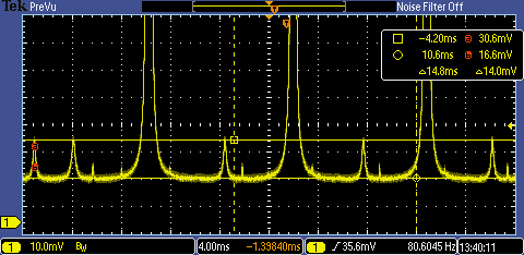
First, we rotated HWP then measured the peak height of the s-pol peak and the p-pol peak.
|
BAB HWP angle |
286.5 |
290 |
294 |
298 |
302 |
306 |
310 |
314 |
|
s-pol (mV) |
4560 |
4400 |
4120 |
3720 |
3240 |
2640 |
1960 |
1440 |
|
p-pol (mV) |
2 |
95 |
372 |
880 |
1400 |
2080 |
2840 |
3480 |
We derived visibility from the peak height difference. We also considered the loss introduced by non-optimal visibility is the square of (1-visibility).
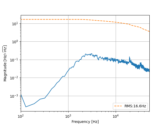
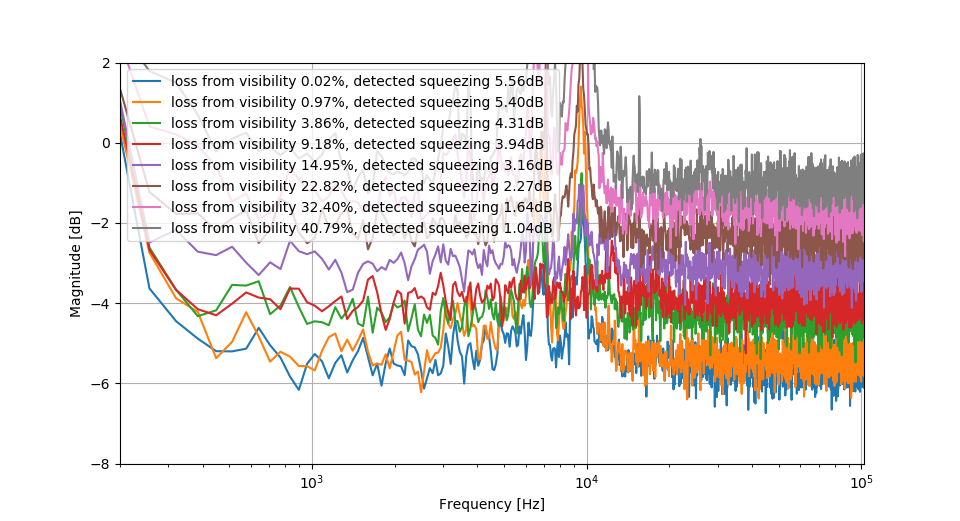
Then we removed BAB and put again CC and pump. We measured only squeezing at the previous HWP angle. (Now I realize that it will be better to measure anti-squeezing) Anyway, the measurement result is attached to the first picture.
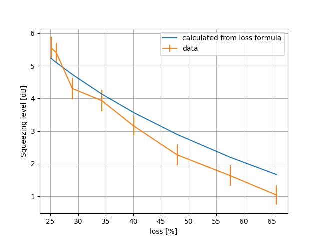
Finally, by using the formula of FIS degradation, we plotted the calculated squeezing value and compared it with measurement. The result is attached to the second picture. However, it seems data and calculation don't match very well.
I think it's better to measure visibility directly.
>> We also considered the loss introduced by non-optimal visibility is the square of (1-visibility).
This seems not correct. This is how I calculated additional loss in entry 1587.
1. Measure voltage of LO, BAB (HWP 0deg), DC offset, visibility (HWP 0deg)
2. Rotate HWP and measure maximum and minimum of visibility
3. Solve the following equation in terms of V_BAB
(V_max-V_min)/(V_max+V_min-2*V_DC)/(2*sqrt((V_LO-V_DC)*(V_BAB-V_DC))/(V_LO+V_BAB-2*V_DC)) == visibility (HWP 0deg)
4. Additional loss should be 1-V_BAB/V_BAB (HWP 0deg)
I am sorry that what I wrote is wrong. The additional loss is 1-visibility**2. I think it is very clear for us that the efficiency of homodyne is visibility**2. This is written in Henning's thesis.
I did re-alignment work of HOMs' paths and beam profile measurement.
The results of the measurement will be uploaded tomorrow...
The attached picture is a current situation of HOMs.
The purpose of the alignment work was to determine the beam paths of HOMs.
Since I put a BS in order to pick off both HOMs and detect the beat note between them which will contain coating thermal noise information.
One of the HOMs beam pass through the BS and another one is reflected.
Then both of them entered a PBS which is used for combining TEM00 and HOMs.
[Next Step]
Install mode matching lenses for each beam path.
I need to buy some posts for them.
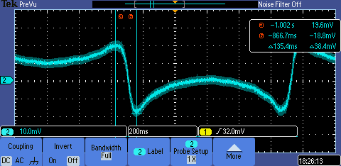
PItch BS channel shows an excess of noise. Damp loops are open and even if I remove DC on coils for the aligment, noise is still there.
This was observed serveral times recently and after a while it goes back by itself. I think it is something electronic, but what?

Yaochin and Yuhang
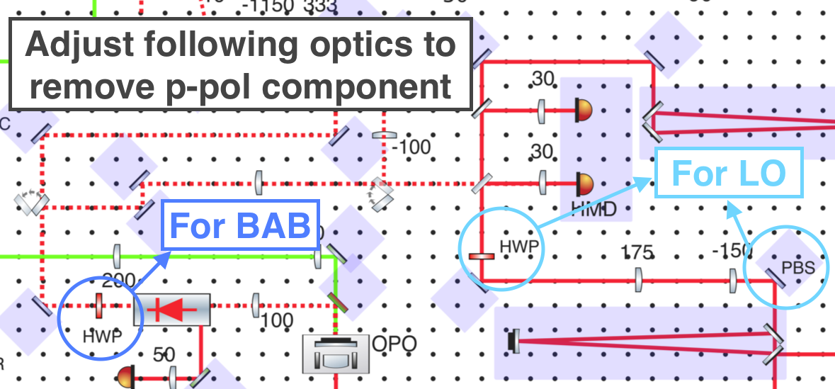
As we reported in elog1867 and elog1857, we improved the matching between LO/BAB into AMC. However, we didn't care about the residual p-pol component after the optimization. And actually, it is really necessary to optimize them and remove the p-pol component.
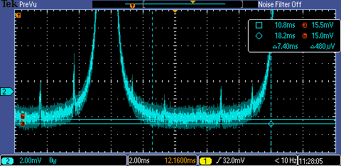
LO part (The AMC spectrum before the change is attached as picture 2) (s-pol 11V, p-pol 14mV)
Actually, I am confused that how can we have a p-pol component from LO. Because LO is provided by IRMC TEM00, TEM00 should provide a quite clean s-pol light.
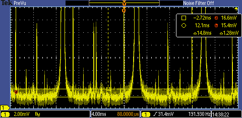
1. We replaced the first mirror after IRMC with a PBS plate.
After this, the p-pol peak is reduced from 14mV to 9mV(attached picture 3). (We also double-checked that total power doesn't change after the replacement of PBS, so this p-pol reduction is a real reduction effect from PBS)
2. We put an HWP just before homodyne BS.
By rotating HWP, we could almost remove the p-pol component totally(attached picture 4).
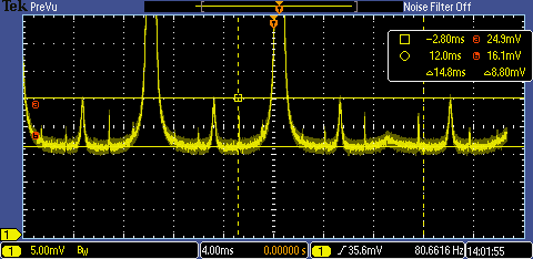
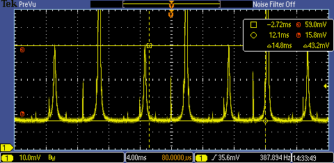
BAB part (The AMC spectrum before the change is attached as picture 5) (s-pol 4V, p-pol 43.2mV)
For the p-pol component inside BAB, it comes from the not optimized HWP. So we just rotate HWP. And then the p-pol is basically removed totally. (attached picture 6)
|
BAB HWP angle |
286.5 |
|
LO HWP angle |
178 |
We measured the squeezing spectrum before and after this change, but there is no obvious change.
Yaochin and Yuhang
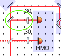
We found we could balance homodyne by aligning the flipping mirror and the lens before the far 'eye' of homodyne. (As shown in the attached figure)
By aligning pitch/yaw of flipping mirror and pitch of lens, we could also recover the balance of homodyne.
Today Miyakawa-san managed to solve the long-lasting problem we had to run python script called by medm button (see entry #1656).
He modified the command used by the medm desktop icon to call medm to: bash -c 'source /kagra/apps/etc/client-user-env_tama.sh && cd /opt/rtcds/kamioka/k1/medm && /opt/rtapps/epics/extensions/bin/linux-x86_64/medm -x sitemap.adl'
Now the command is also calling a script he made (/kagra/apps/etc/client-user-env_tama.sh) to include all the needed evironmental variables.
Somehow when opening MEDM with this command the PV info on the channel cannot be seen anymore. The icon MEDM (edit) was not changed so, by using that one, we can still read PV info ( but not run python scripts)
Conlusion: we can now run python screep from MEDM screen open by desktop icon, and this should help to better manage control loops, while we wait for guardians.
Yuhang and Yaochin
We reported sometimes the CC1 loop cannot be locked.
Today we found the cable which is sending error signal for the loop has some connection problem. When we shake the cable, the error signal sent to the loop got a lot of noise.
We have already replaced it with a new cable. We checked the new cable doesn't introduce noise when we shake it.