NAOJ GW Elog Logbook 3.2

Michael and Yuhang
Today, we have successfully closed OPO cavity. The OPO no.28 component issue is solved by replacing it with a longer screw.
After cavity closed, we optimized OPO cavity alignment relative to its incident beam. However, we found the scan spectrum is as Fig.1.
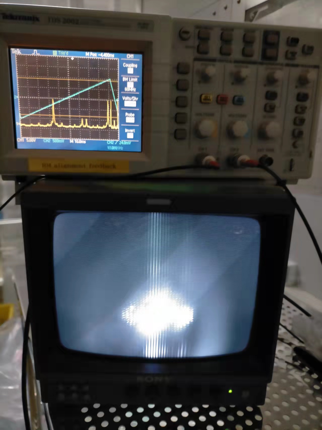
1. We can see that there are apparently two higher order modes in the scan spectrum. By scanning OPO cavity with 10mHz ramp and looking at a designated camera , we found that the higher order modes are second-order Hermit Gaussian modes. (The cavity scan video is here https://drive.google.com/file/d/1Od2jI40D_3oZuZksuI474tunwtt7znIs/view?usp=sharing , note that it seems cavity mode is not centered in a circle. But this circle is just a mirror. The cavity mode looks to be well centered when mirror is removed.)
2. We can also see that there are modes overlapping with TEM00 mode. It indicates that we are having a cavity length which offers a non-ideal Gouy phase.
3. When we misalign pitch or yaw of the incident beam, we found the first order mode appears but the existing second order mode decreases. This is wired for me.
4. We have identified a potential beam clipping in the optical path before OPO. After fixing the clipping issue, we didn't get better OPO scanning spectrum.
5. We suspect that we may fix either crystal or in-coupling mirror too tightly, so that mirror has distortion and introduces higher order modes. After loosing a bit the screws, we didn't see improvement.
6. We suspect that there maybe some contamination. Especially, the crystal was in air for several months. But we are not sure if contamination is really true because the cleanroom in ATC is designed to be a class 10 cleanroom.
Personally, I think we need to open OPO again and adjust maybe crystal position.
Abe, Marc (with help of Michael and Yuhang to safely move the spare ETMY)
First we removed the spare ETMY.
Then, we used the razor blade and high power power meter connected to the lock-in amplifier DC to check the pump beam angle of incidence in vertical and horizontal planes. (analysis to follow)
We installed the surface reference sample and got R ~15.7 /W without tuning the alignment.
We tuned the alignment and got R_surface = 18.537 /W with Z_translationStage = 42 mm and Z_IU = 66 mm.
We also measured R_bulk = 0.6703 cm/W.
We reinstalled the spare ETMY with the 2 ears flat (ie same configuration as in entry 2755.
We tuned Z_IU to 5.4 mm taking into account the thickness after repolishing (14.3 cm instead of 15 cm).
We started to look for the 2 surfaces signal increasing the input pump power from 2W to about 7W (in transmission of the spare ETMY).
At that point we may have seen the expected signal with median and average filters order 10 but because the step size was 0.2mm we could not clearly see them.
For reference, the last time that the spare ETMY absorption has been measured the input pump power was about 10 W (see for example entry 1601)
As it was getting late on Christmas eve we stopped there and will start absorption measurement on monday.
Aritomi, Yuhang
There was an earthquake on 12th Dec. which caused mis-alignment of suspended mirrors. We worked on the re-alignment on 22th Dec. During the re-alignment, we found that the BS picomotor can be only moved in pitch direction but not in yaw direction. Fortunately, we were able to bring back the filter cavity alignment even in this situation.
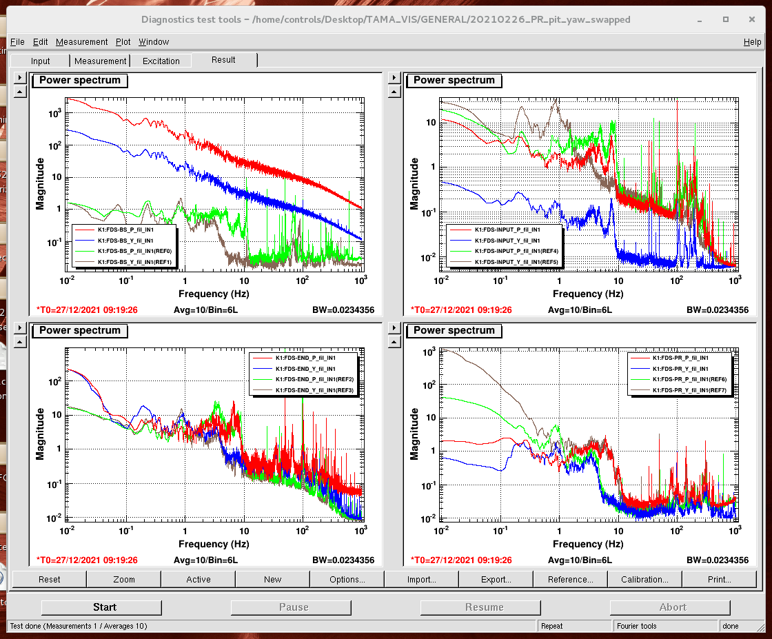
Since BS picomotor couldn't be moved in yaw direction, we looked into the BS oplev spectrum. The result is shown in Fig.1 and we can see that the oplev signal is totally off from the nominal value. Note that input oplev was different because we took pre-amplifier from input temporarily.
For the time being, we can still work with this condition. But maybe we should correct BS mirror from touching in the near future.
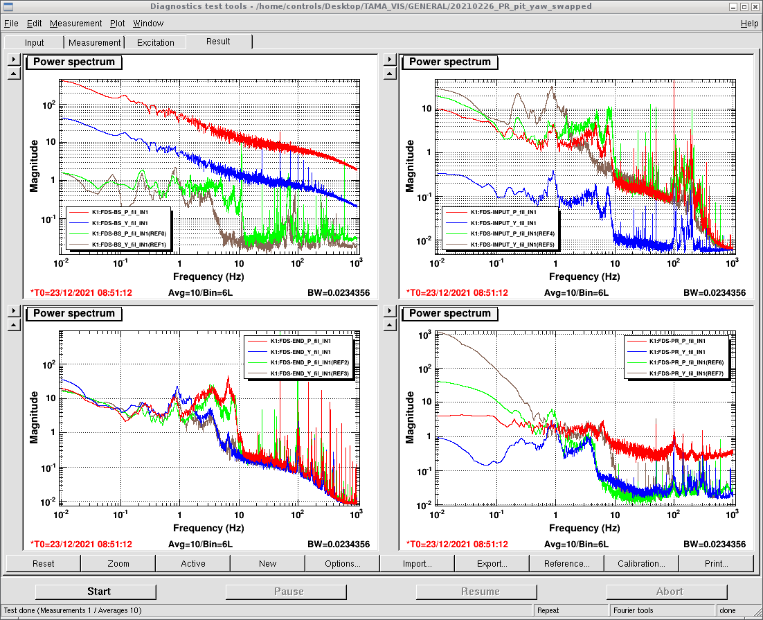
The BS issue has been checked again today by switching off the oplev laser since I was suspecting that BS PSD maybe broken. Indeed, after switching off BS oplev laser, the BS oplev signal is as Fig.1 which is the same as what is taken last Thursday. So the strange signal we are seeing is from the broken BS PSD.
To confirm the health of BS suspension, we need to take an another PSD and use it to characterize BS suspension.
[Aritomi, Yuhang]
We continued the investigation of the 20kHz peaks in FC green error signal. We checked the IRMC error signal and there are no 20kHz peaks in the IRMC error signal. So the 20kHz peaks should not come from laser.
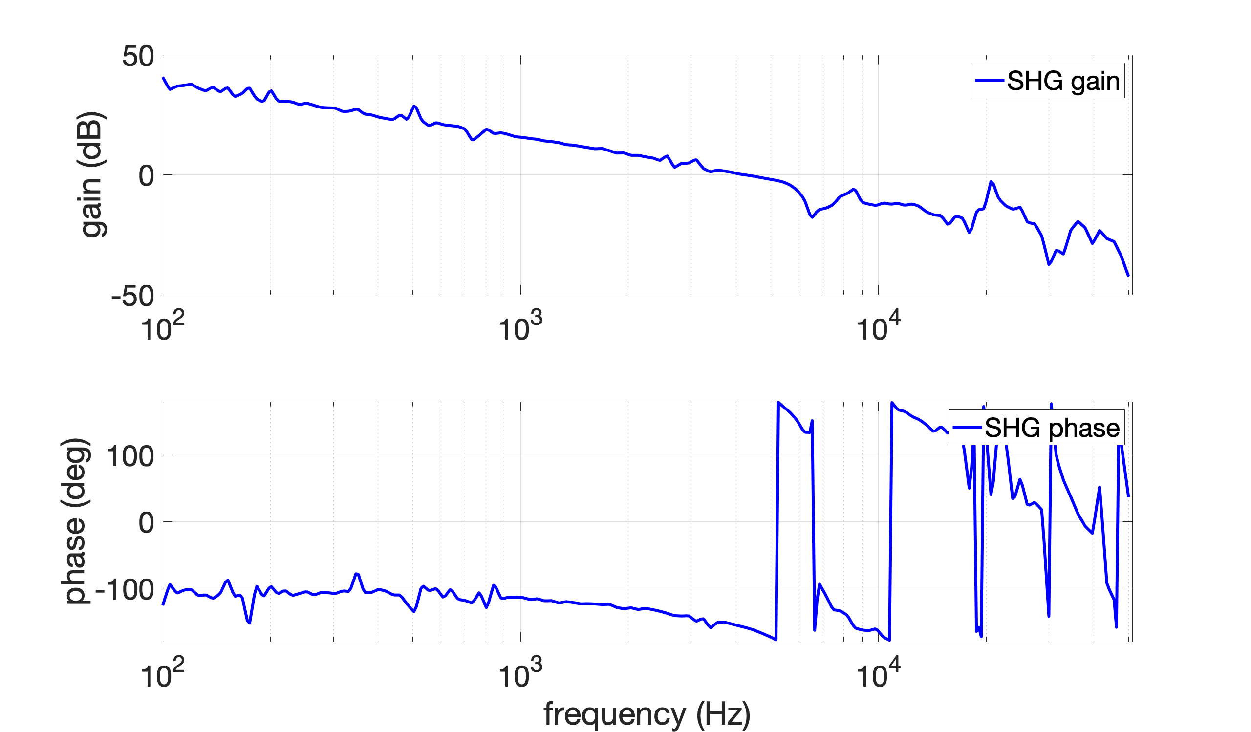
Then we measured SHG OLTF and found that there is a peak around 20kHz as shown in Fig 1. In this measurement, the SHG gain was 1.3. We decreased the SHG gain from 1.3 to 1 to avoid the 20kHz peak, but the FC green error signal is still noisy.
Regarding the Z correction, we found that the dc_damp2 filter was completely different from the one written in elog2608. We changed the dc_damp2 filter to the one written in elog2608. We set the dc_damp2 filter gain as 10 in foton and 4 in medm. However, FC is still not very stable.
Marc, Michael
To facilitate the removal of the mirror, we used the knob controller of X direction to move the mirror.
After that, we found out that the Zaber reading got good so we started the measurement with 45 deg input polarization angle.
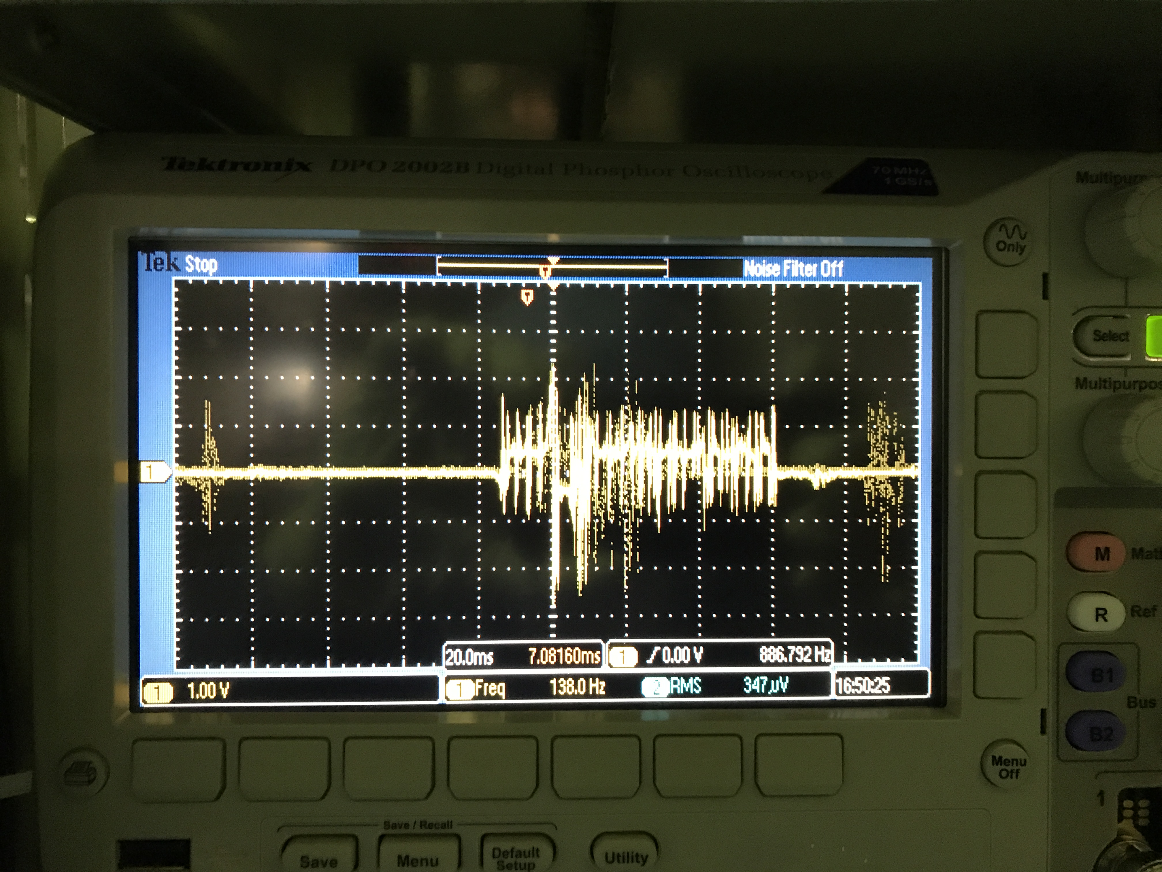
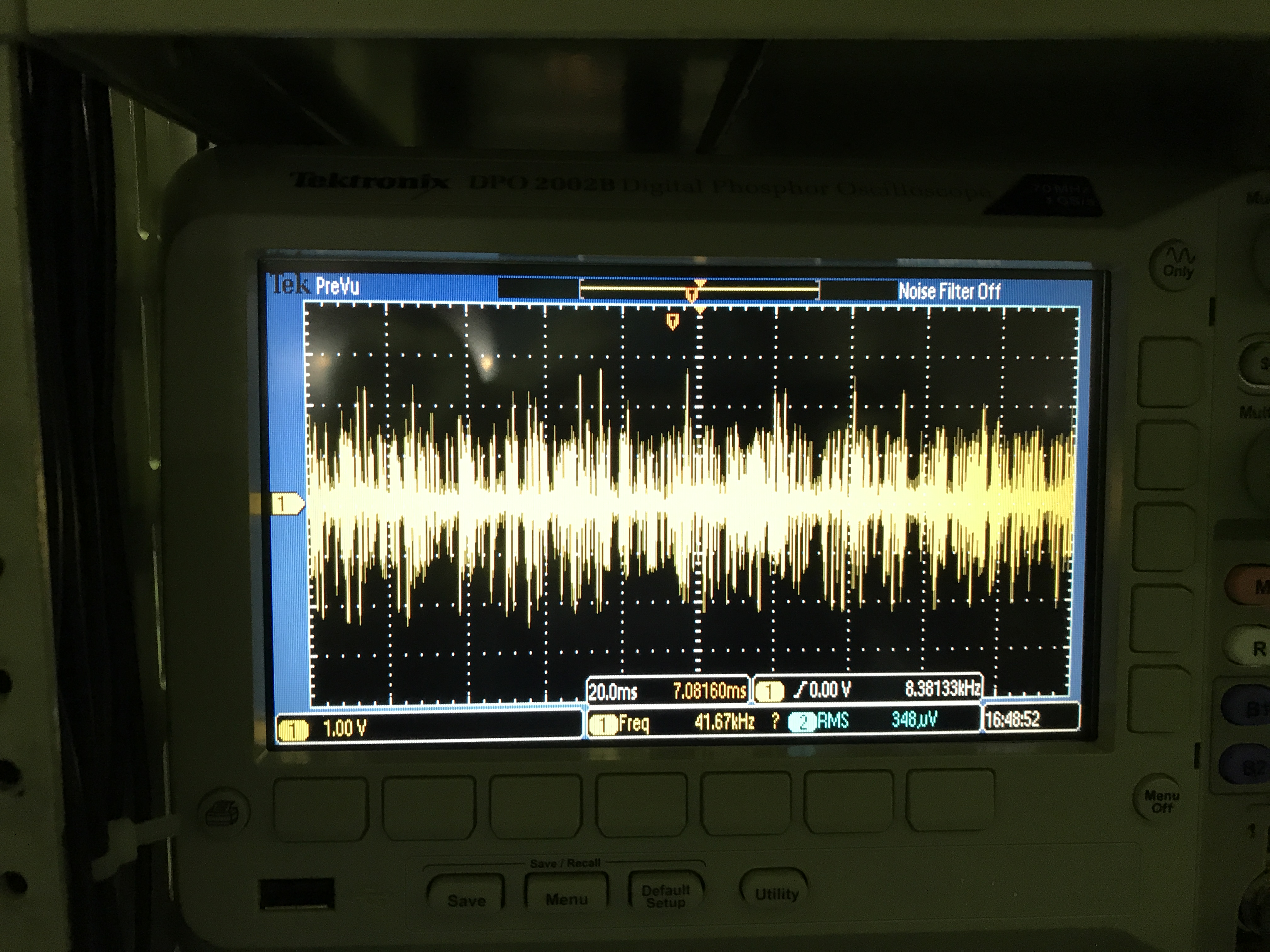
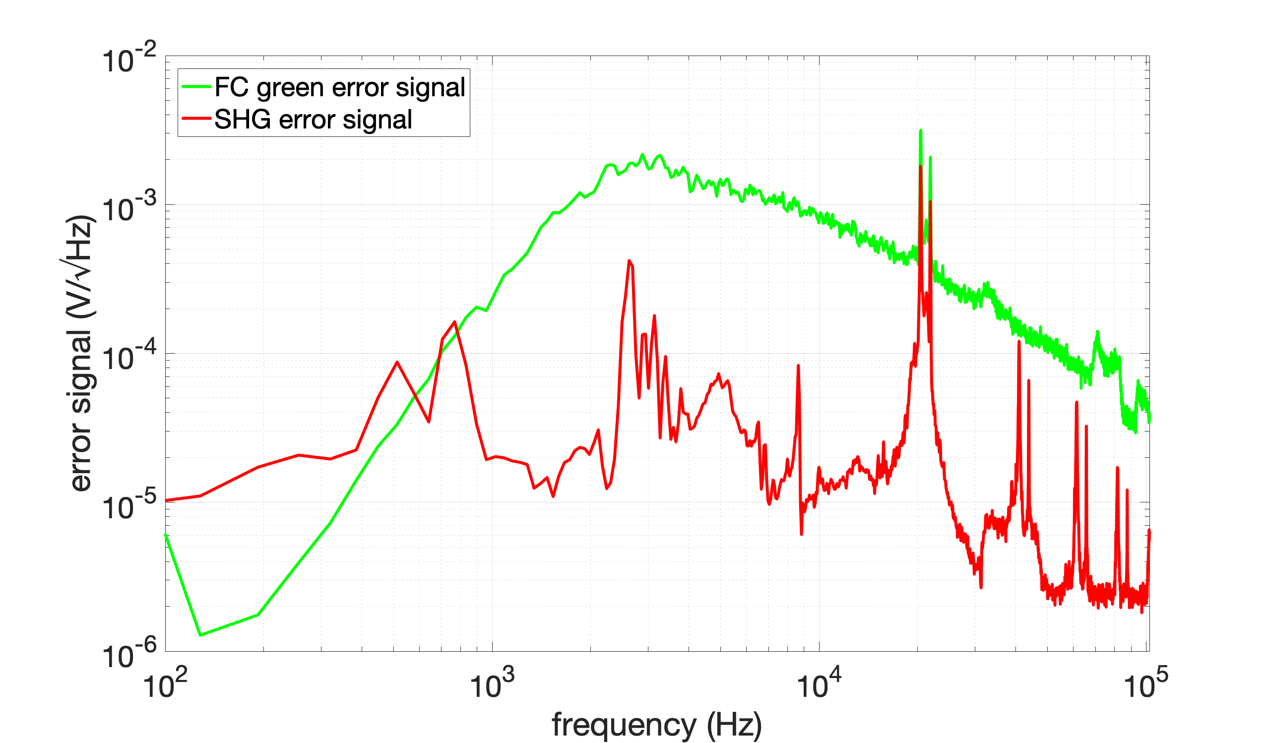
We found that FC green error signal is very noisy. Fig 1,2 show the FC green error signal before/after lock. Fig 3 shows the spectrum of the FC green error signal after lock. There are two peaks around 20 kHz in the FC green error signal. It seems that the two peaks come from SHG. The SHG error signal is also shown in Fig 3. The SHG gain was 1.4. We decreased the SHG gain from 1.4 to 1, but the peaks around 20 kHz did not change.
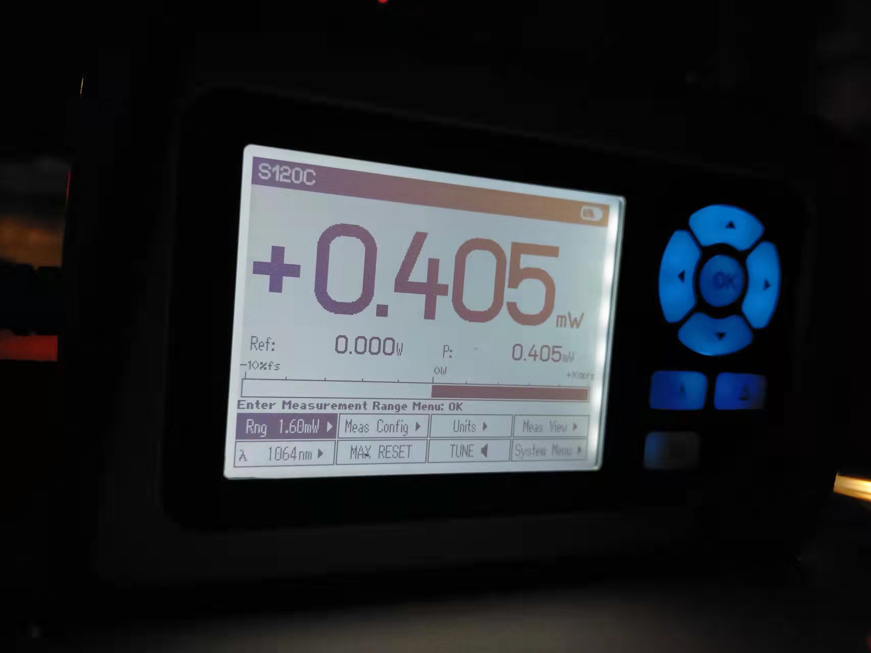
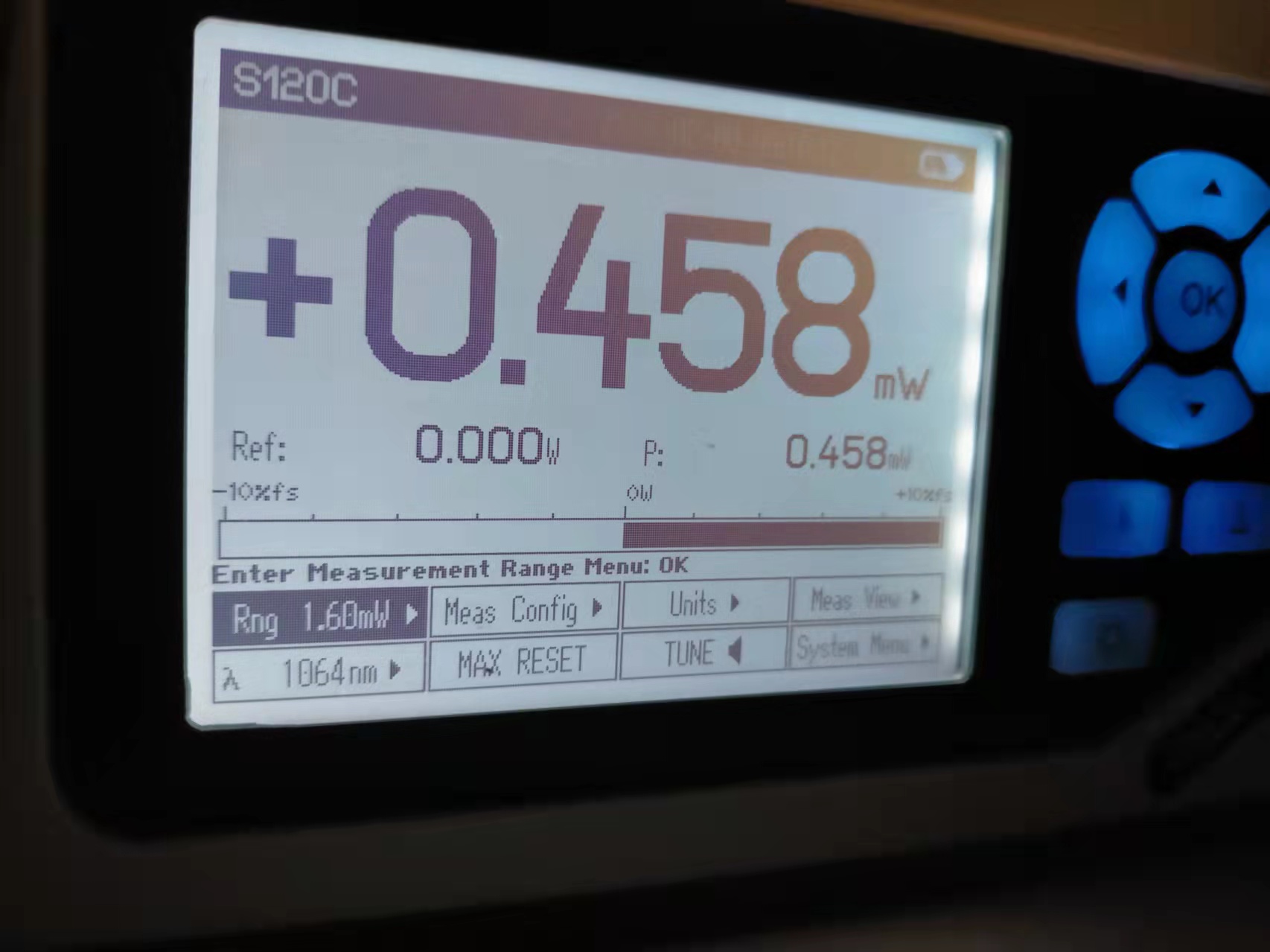
During this investigation, we checked green power and OLTF of FC green lock. The measured green power is as follows. The green power seems reasonable. The UGF was 14kHz, which is also reasonable. Note that FC gain was 1.6.
| green power before AOM | 48.6 mW |
| green power before FC | 24.3 mW |
We also found that the Z correction is not very stable. We quickly checked the filters in filter bank of Z correction as follows.
| not bad filters | damp, damp2 |
| bad filters | DCdamp, dc_damp2, dc_damp3 |
The bad filters immediately caused FC unlock when they were engaged. The not bad filters didn't cause the immediate unlock, but FC was not very stable for long term. We need to investigate the Z correction.
Michael and Yuhang
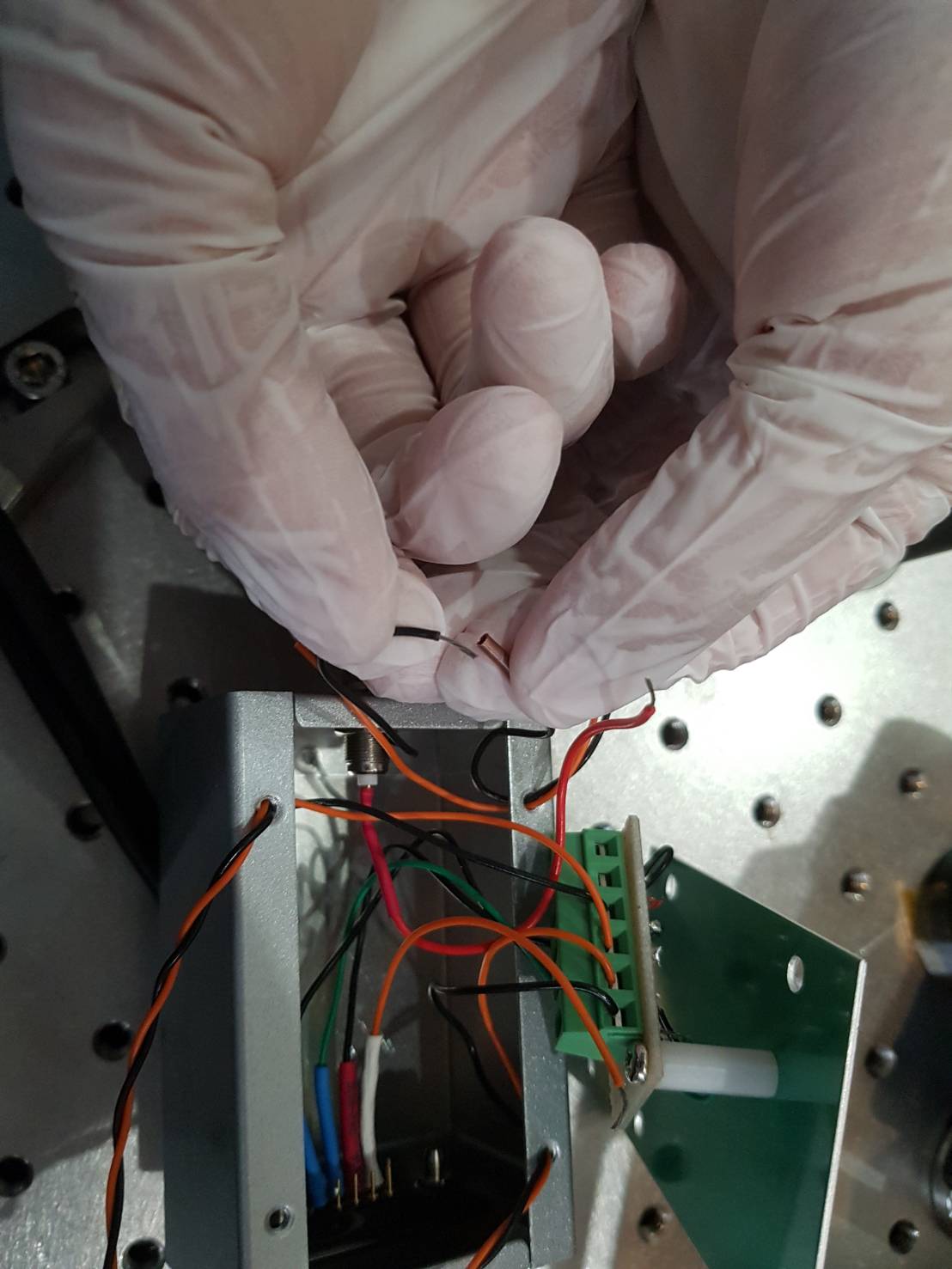
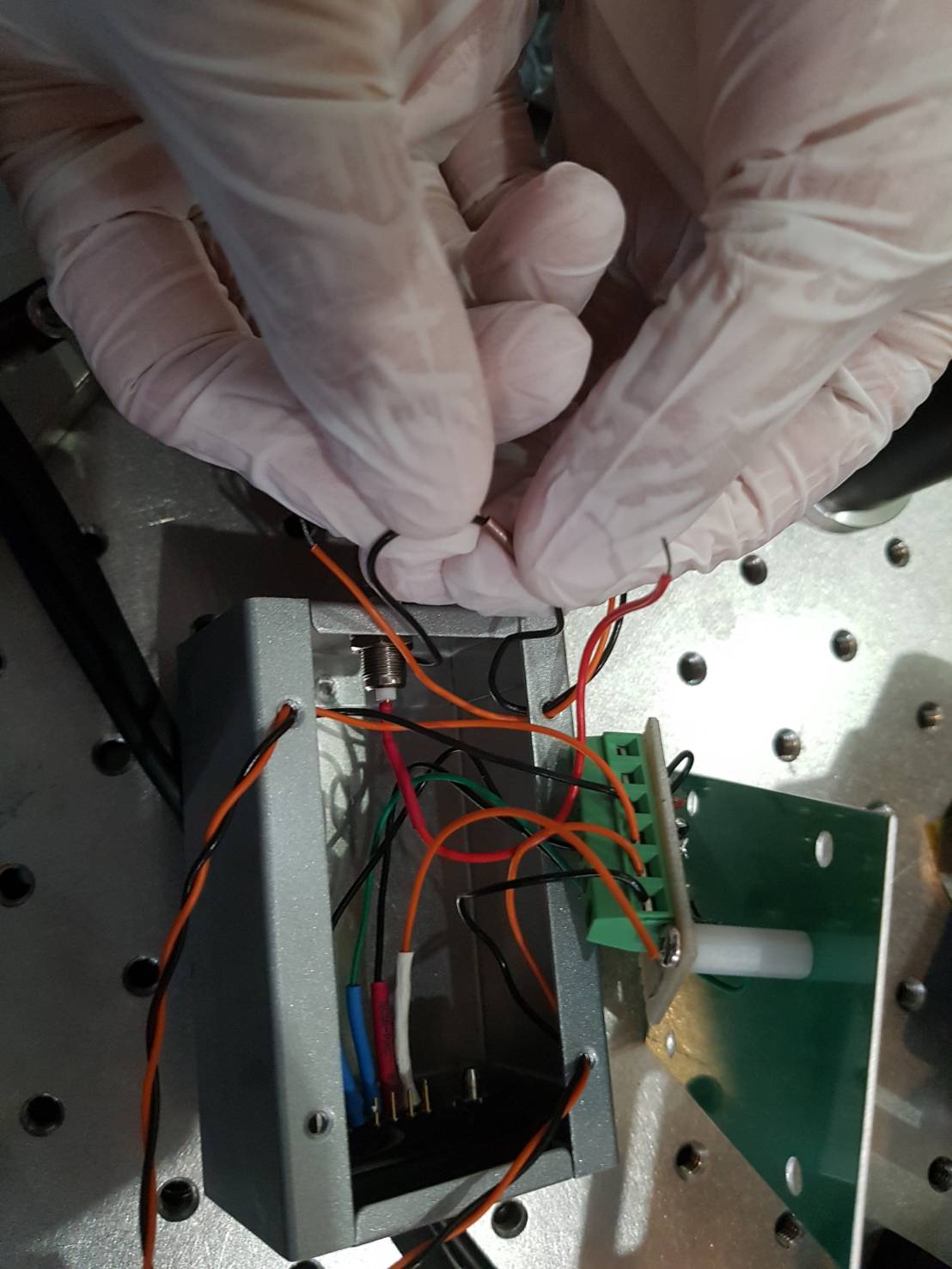
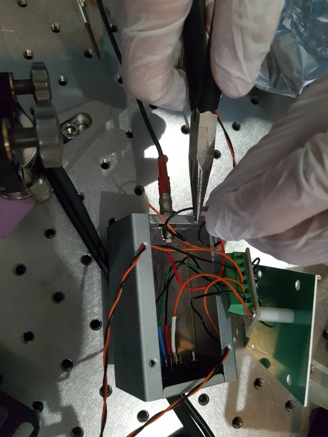
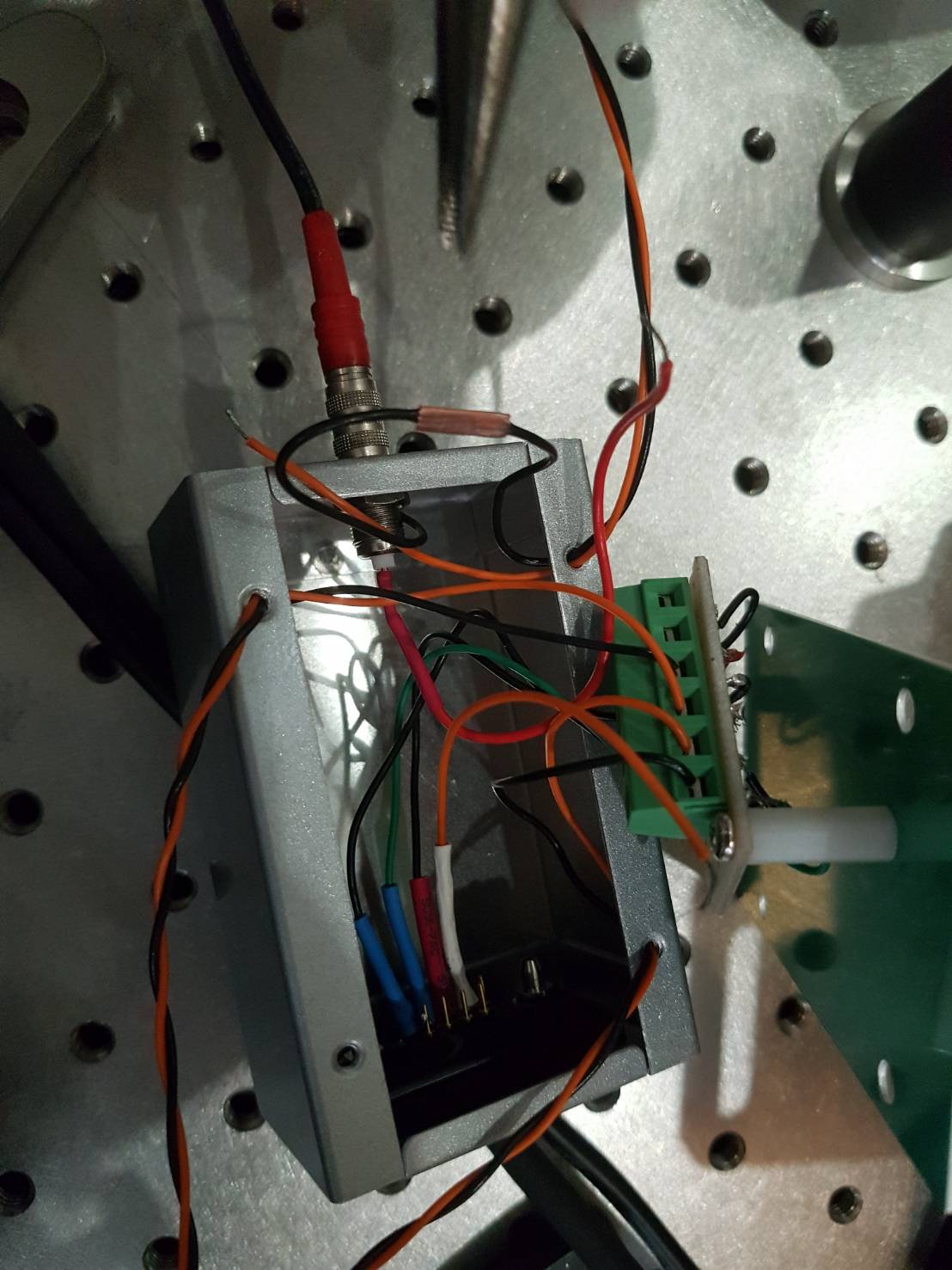
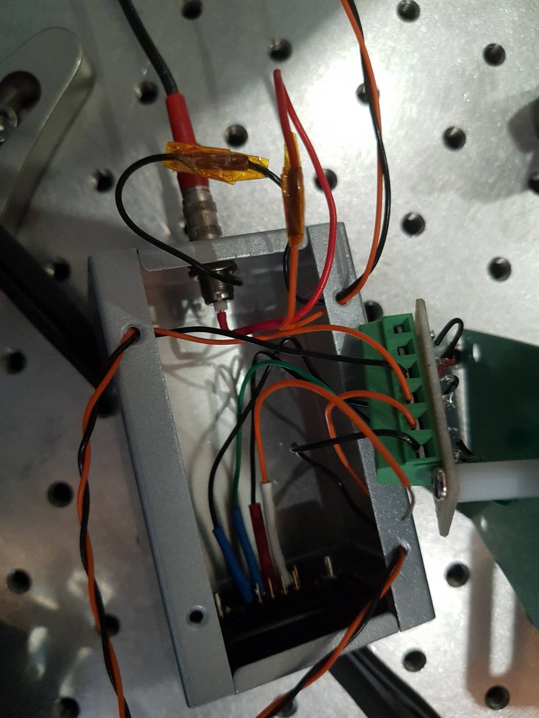
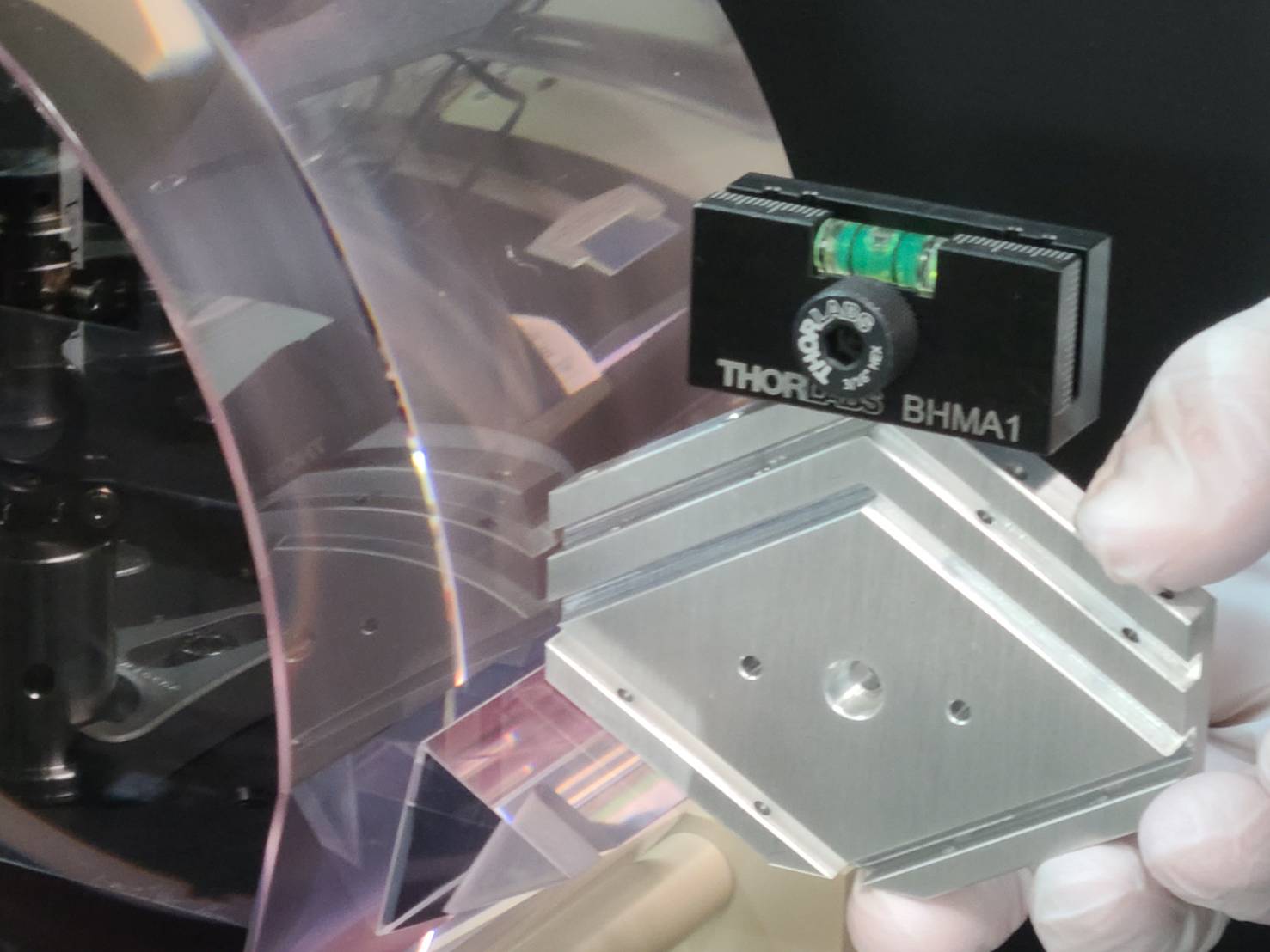
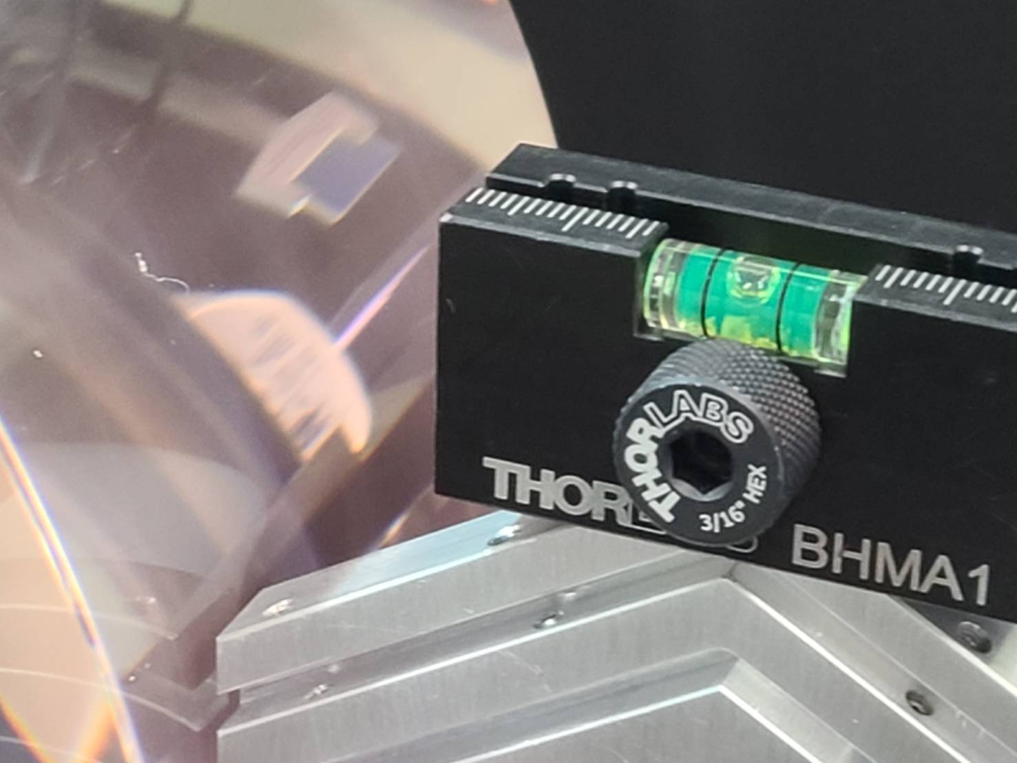
Some cables need to be connected to the new OPO, such as PZT cables, thermometer cables, and Peltier cables. The old connection was not firm enough and we decide to use a new way to connect cables. This new way is suggested by Tomaru-san and it uses a copper tube as interface. After putting the two sides of cables inside the copper tube (Fig.1,2), we use a plier to clamp two cables so that the cables are fixed (Fig.3,4). Then we use Kapton tape to isolate the copper tube from environment (Fig.5).
After fixing, we found the connection is firm enough. We also tried to drive PZT and found the driving is successful.
Michael and Yuhang
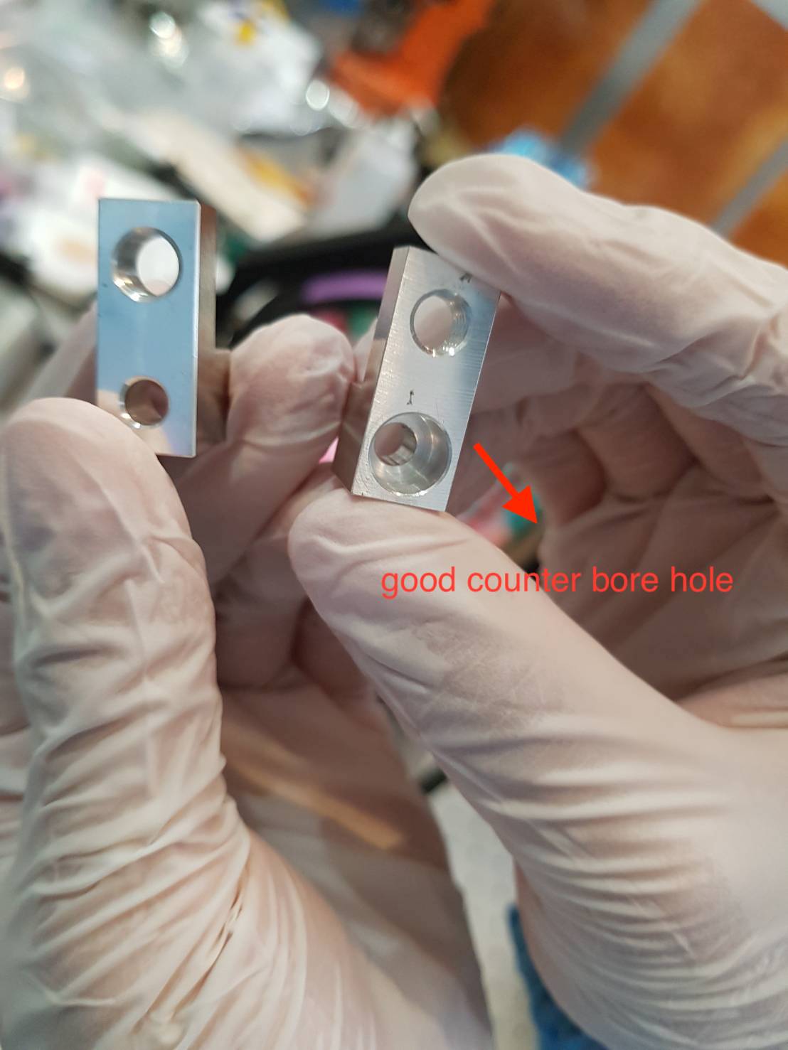
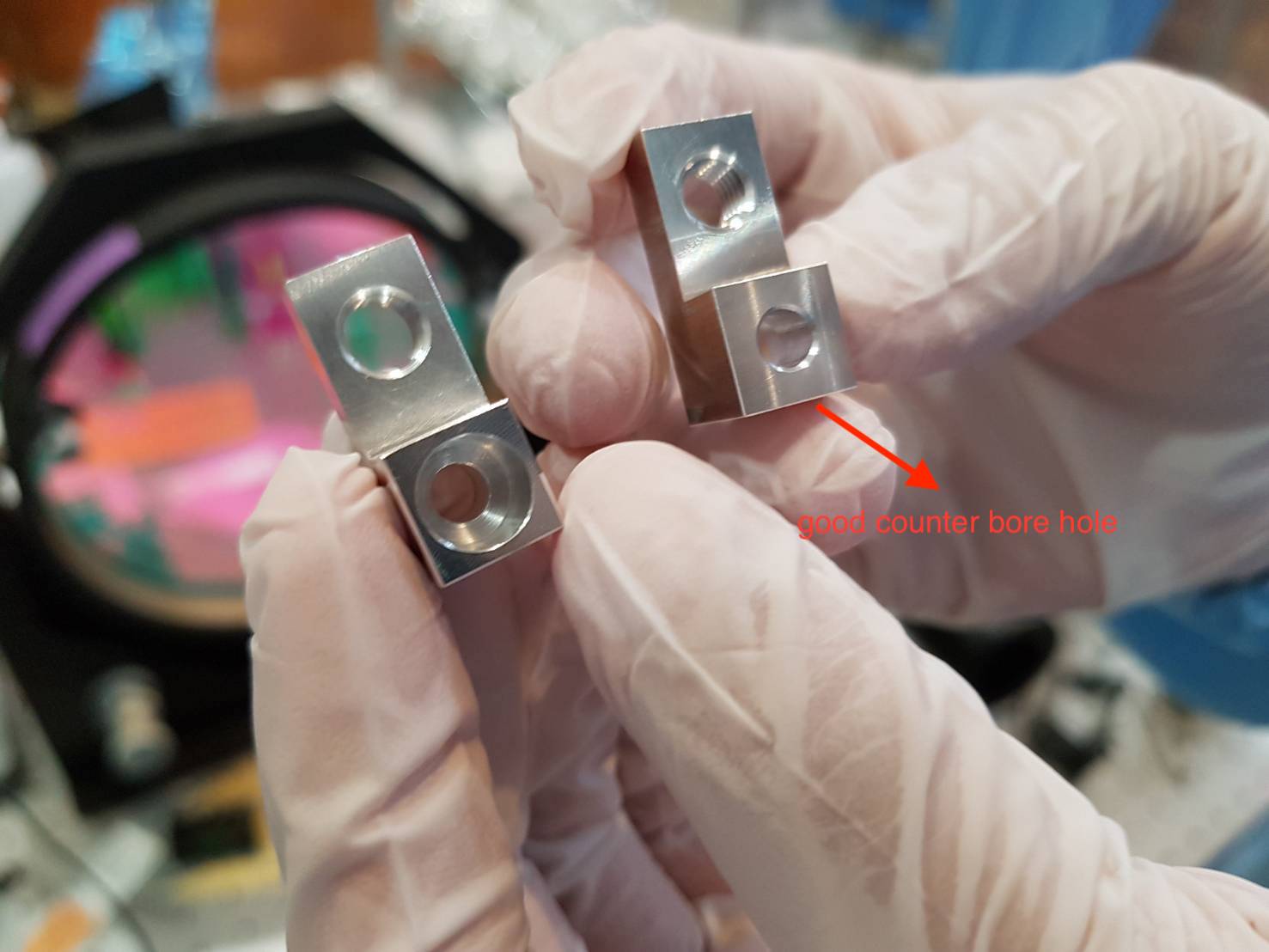
Today we found a new issue about new OPO component No.28. The issue is described in the attached PDF file. The issue is that a counter bore hole is made from a wrong side of no.28 component.
We also took photos about no.28 component with wrong and correct holes, as shown in the attached Fig. 1 and 2. (The one with correct hole actually has wrong thread as reported in elog2724)
For solution, we found that a longer screw seems to be able to solve the problem. We will look for some longer screws and clean them. Then try to use them for the new OPO.

Again issue with the translation stage so we have to remove the mirror to reset the motors reading from Zaber..
I deactivated the windows update for 1 month
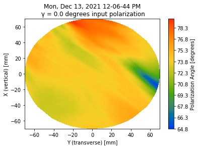
I checked data especially of the measurement with 45deg input polarization angle.
It seems there was some issue with the calibration of the DC signal (the DC with approximately 45 deg input polarization is higher by a factor 2 than the expected maximum value when we inject pure p polarization).
We will redo this measurement again today.
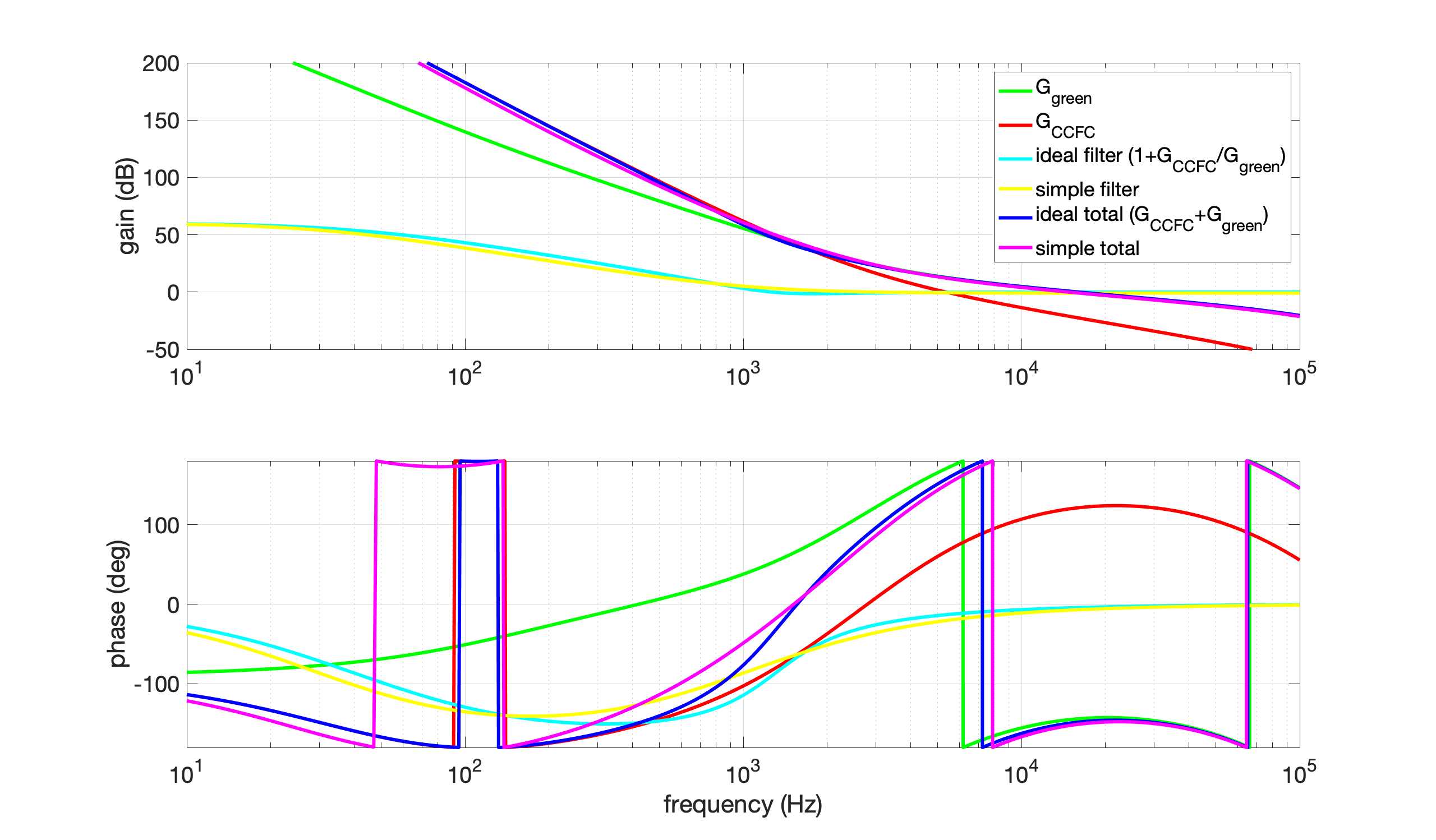
To realize the CCFC+green OLTF with green only, we need the following green filter.
1 + G_CCFC/G_green = 1 + P_CCFC/P_green*G_f*P_f
where G_CCFC, G_green are the OLTF of CCFC and green, P_CCFC, P_green are the cavity pole of CCFC and green, and G_f = 1000, P_f are gain and pole of the CCFC filter. The pole P can be written as
P = 1/(1+i*f/f_p)
where f_p is the pole frequency. f_p for P_CCFC, P_green, P_f are 57 Hz, 1450 Hz, 30 Hz, respectively.
This ideal filter is complicated to realize with combination of zeros and poles. Instead, we can use a simple filter which is the combination of 2 poles and 2 zeros. The pole and zero frequency are 30 Hz and 1000 Hz, respectively, and gain is 1000. As you can see in the attached figure, the simple filter is similar to the ideal filter.
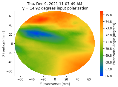
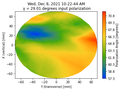
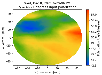
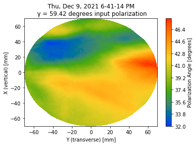
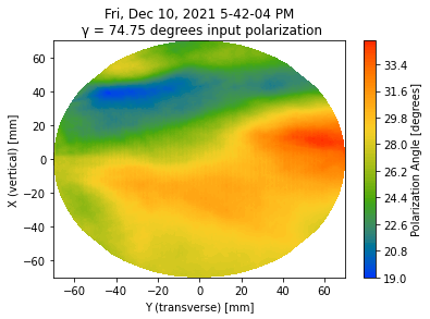
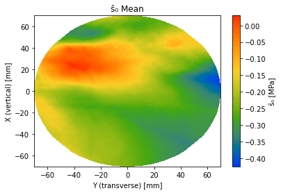
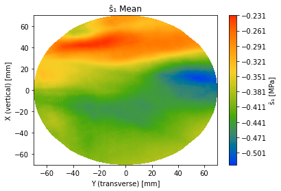
We rotated spare ETMY by almost 30deg.
We followed the same procedure as before the rotation (as entry 2755).
However, the map at 45deg is not working.
So I made birefringence map without 45deg.
I checked data especially of the measurement with 45deg input polarization angle.
It seems there was some issue with the calibration of the DC signal (the DC with approximately 45 deg input polarization is higher by a factor 2 than the expected maximum value when we inject pure p polarization).
We will redo this measurement again today.
Again issue with the translation stage so we have to remove the mirror to reset the motors reading from Zaber..
I deactivated the windows update for 1 month
Marc, Michael
To facilitate the removal of the mirror, we used the knob controller of X direction to move the mirror.
After that, we found out that the Zaber reading got good so we started the measurement with 45 deg input polarization angle.
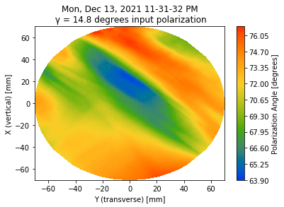
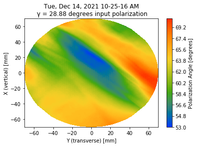
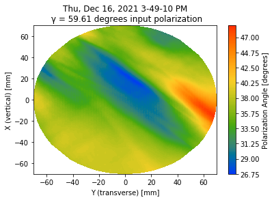
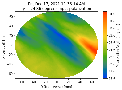
Abe, Katsuki, Marc
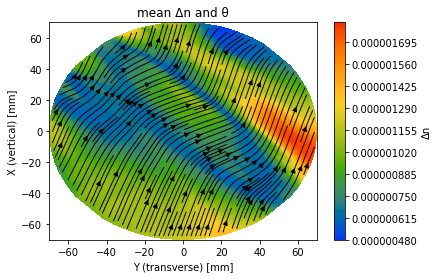
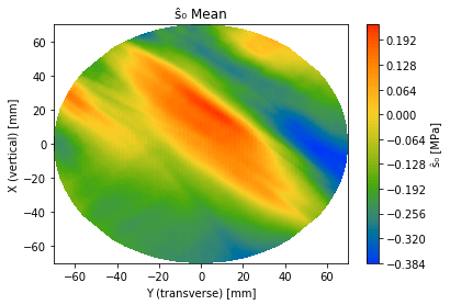
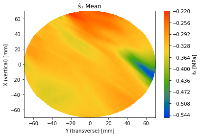
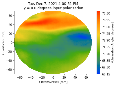
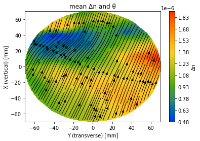
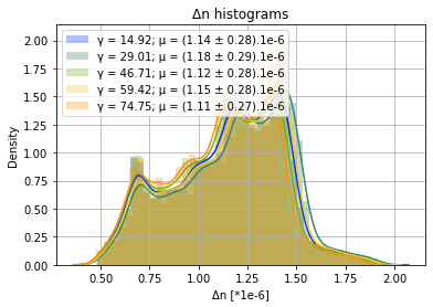
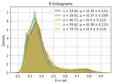
This entry reports the birefringence measurements of spare ETMY without roll rotation (ie with the 2 ears flats).
delta_n and theta seems quite consistent over all measurements.
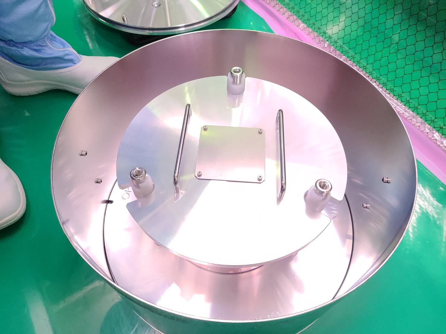
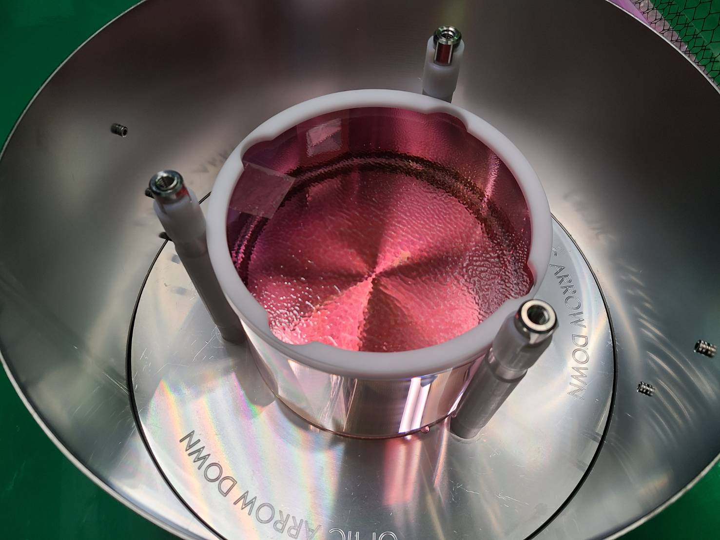
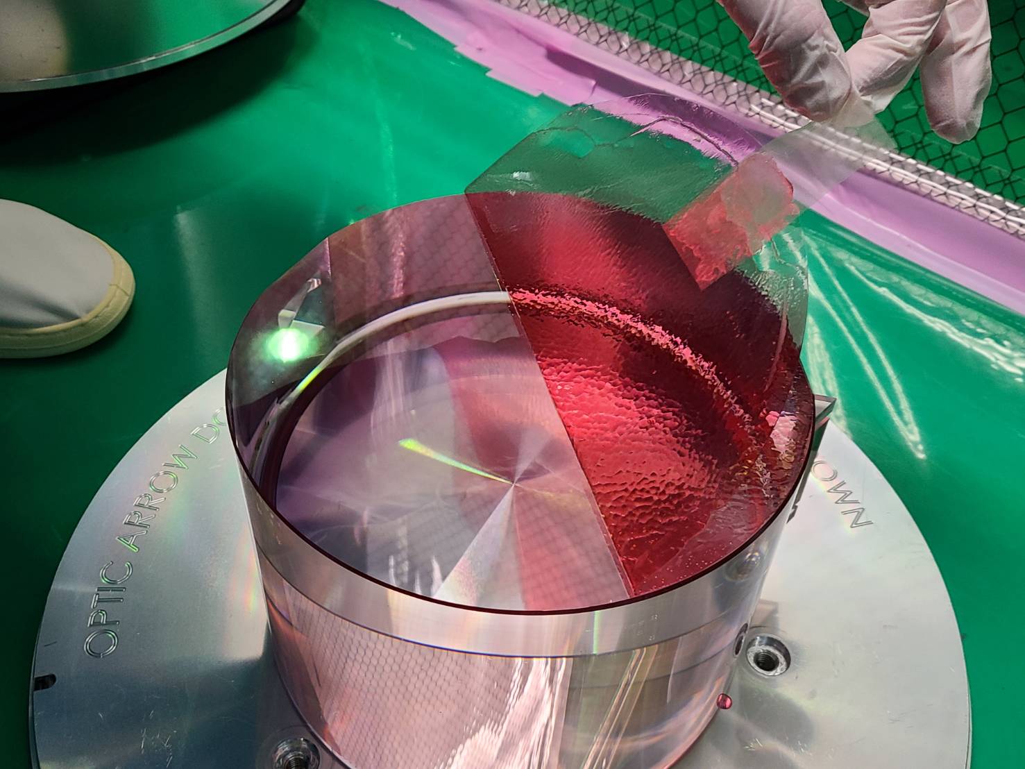
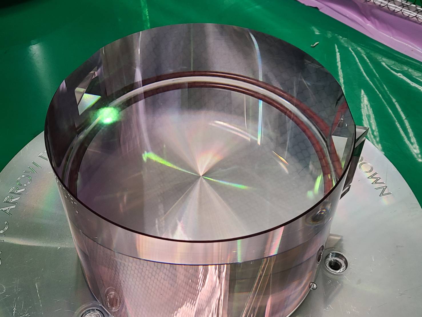
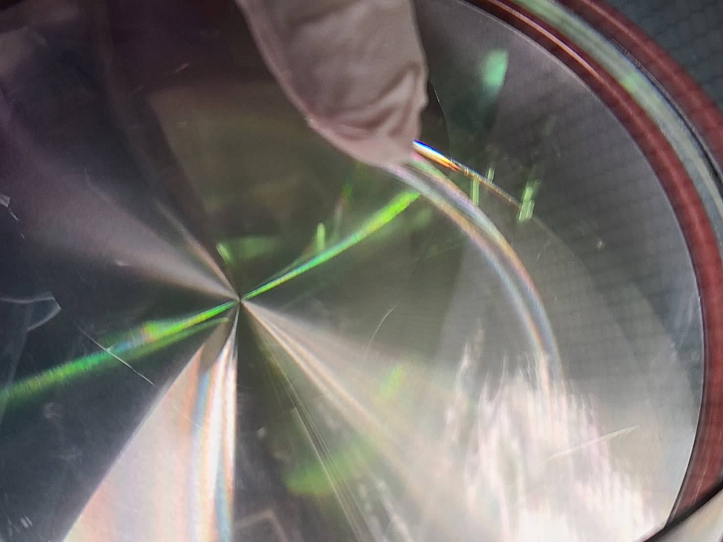
We take back the spare ETMY from Kashiwa.
Attached is a photo of the opening () and the small dust particles mentioned in entry 2749.
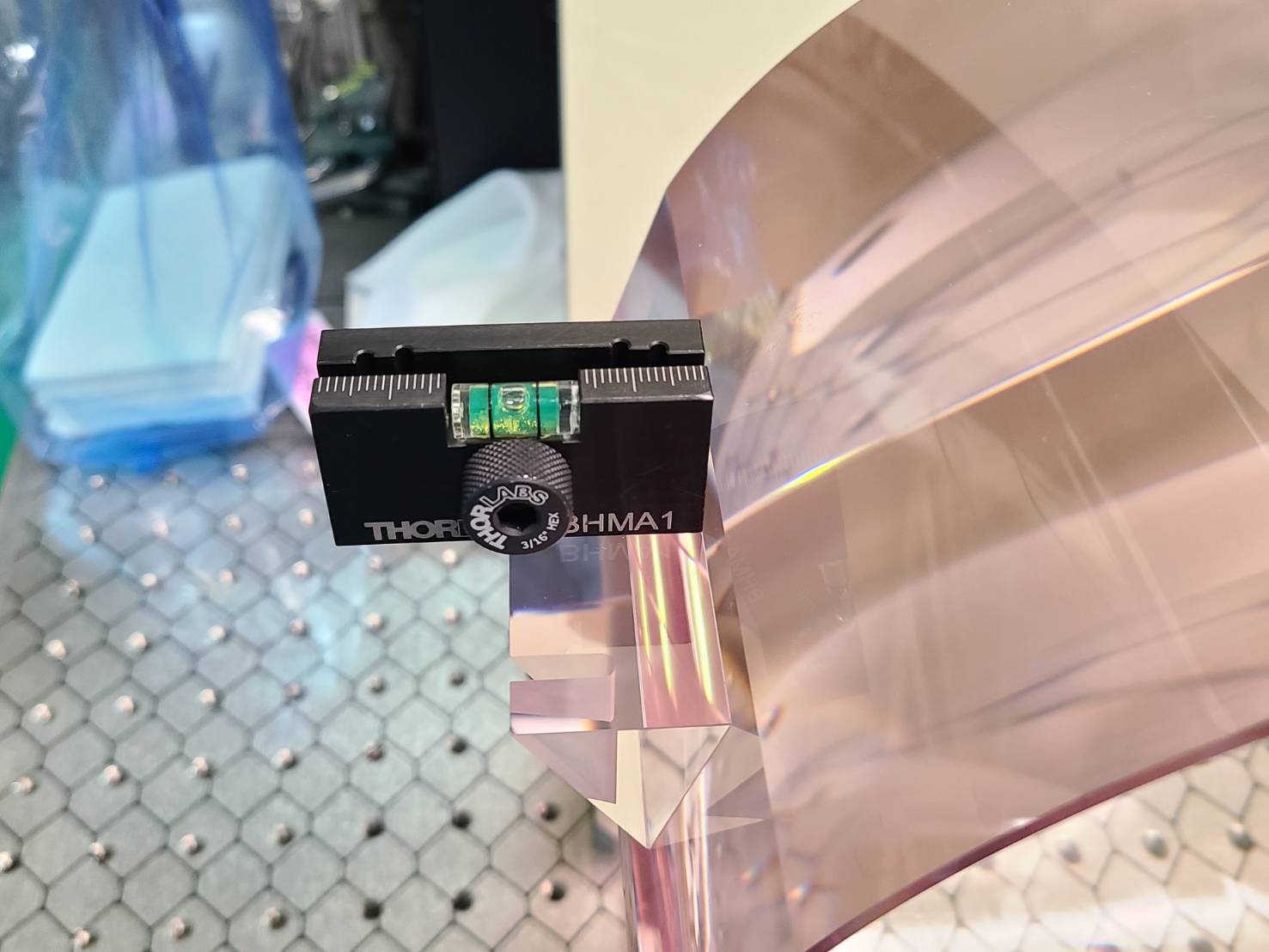
After opening the package, I set it up on the stage so that it was almost horizontal by eyes.
Michael and Yuhang
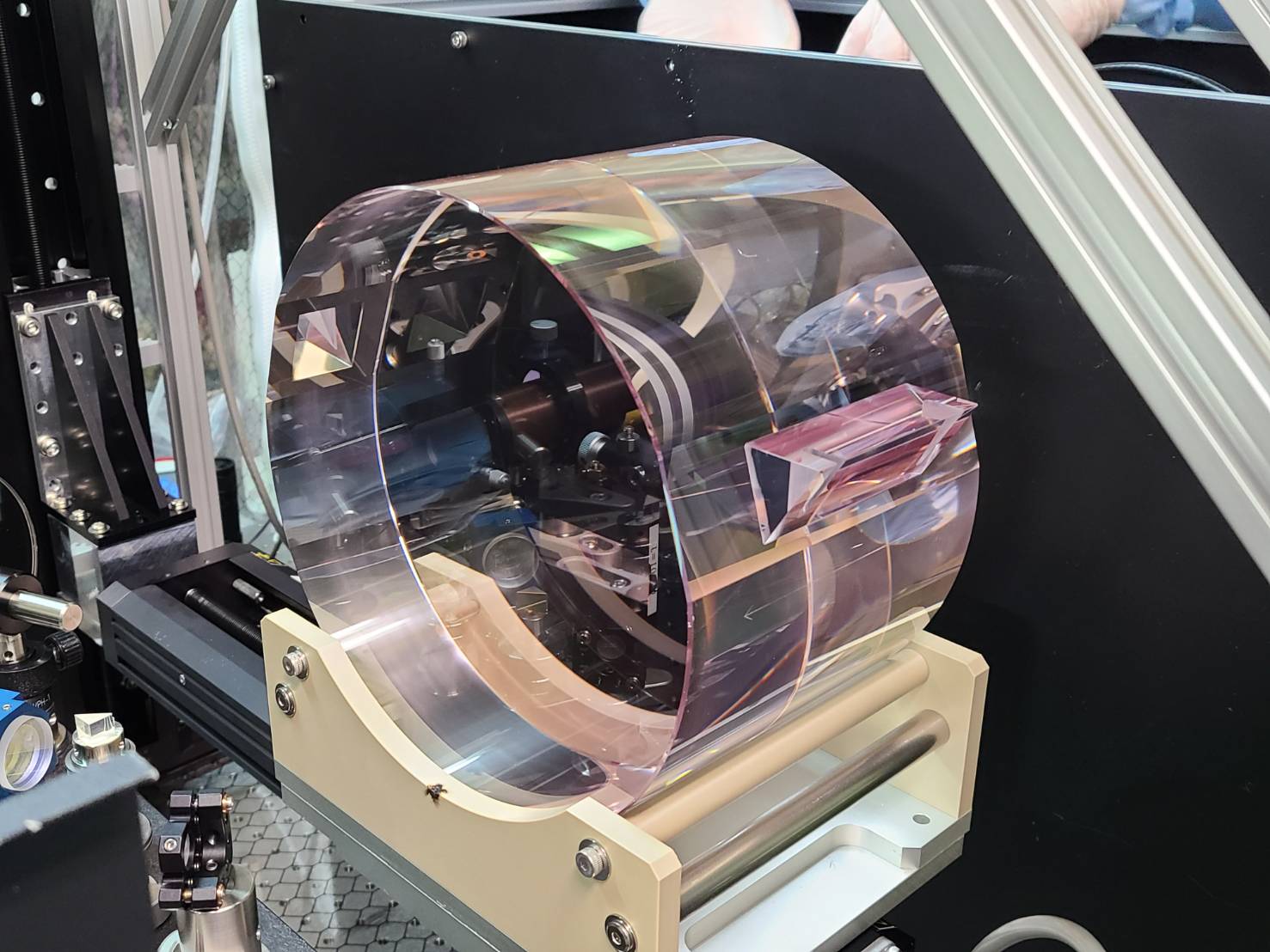
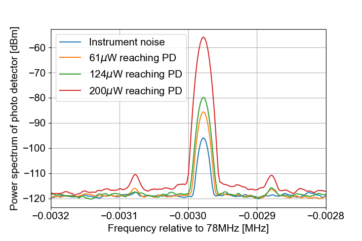
We have measured residual amplitude modulation (RAM) for green beam using the reflection from GRMC.
We use a DC PD to monitor the GRMC reflection power. An RF PD in reflection of GRMC is used for measuring RAM.
We performed PD spectrum measurement several times for different green power going into PD. The result is shown in Fig.1.
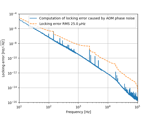
The equation used to find relation between frequency and phase should be restricted inside cavity because it comes from the term phi = 2*pi*(f*L)/c. Since we assume the cavity is kept on resonance, we have relation between f and L. So we don't compare the phase of laser inside and outside cavity.
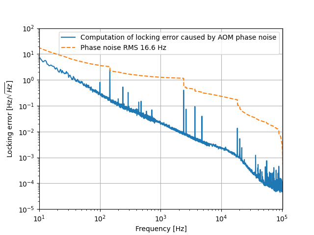
We measured the phase noise introduced by AOM. According to Fourier transform, the frequency noise is phi/f.
Taking phi/f and cavity pole, we get the frequency noise introduced by AOM as Fig.1. We can see AOM introduce negligible frequency noise of only 25 uHz.
Abe-san, Marc, Matteo
Yesterday we installed the spare ETMY on the translation stage.
With eye inspection, we could see dusts on both surfaces that should be cleaned before the absorption measurement.
Using the probe laser we found X_center = 397.5 and Y_center = 111.635.
The Z position is 80 mm which corresponds to beam waists about 1 cm in front of the mirror center.
After alignment and calibration, we took a first measurement with 70 mm radius with s polarization.
A next measurement with polarization angle about 30 deg is on-going
Michael and Yuhang
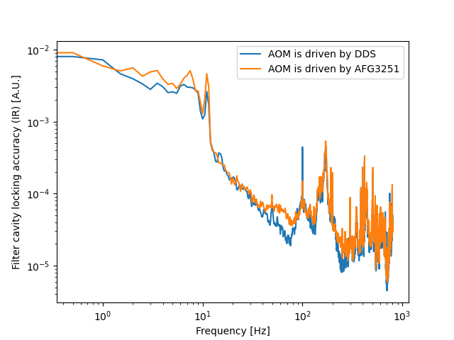
We measured AFG3251 phase noise in elog2745, which shows that it has higher phase noise than DDS (about a factor of 3). Especially, taking the phase noise into account using f = phi*(fsr/2*pi)/2 (wrong) and infrared cavity pole p (transfer function = sqrt(p^2/(p^2+f^2))), we find it gives locking error even larger than what we observe (Fig. 1). The green cavity pole is neglected since it acts at relatively high frequency which almost doesn't contribute to locking error. For the moment, we don't know why it happens.
If the phase noise of AOM driving signal gives any limitation, a less noisy driving signal would provide less locking error. As we know from M. Vardaro thesis, DDS provides signal with less phase noise. Therefore, we measured filter cavity locking error (IR) using DDS and AFG3251 to driving AOM separately. We forgot to calibrate this signal (will be done later), but the comparison of the locking error in these two conditions are as shown in Fig. 2. This indicates AOM driving signal phase noise maybe not a limiting noise source.
The equation used to find relation between frequency and phase should be restricted inside cavity because it comes from the term phi = 2*pi*(f*L)/c. Since we assume the cavity is kept on resonance, we have relation between f and L. So we don't compare the phase of laser inside and outside cavity.
We measured the phase noise introduced by AOM. According to Fourier transform, the frequency noise is phi/f.
Taking phi/f and cavity pole, we get the frequency noise introduced by AOM as Fig.1. We can see AOM introduce negligible frequency noise of only 25 uHz.
Abe, Marc
In order to get the correct limits of the translation stage we had to home every motors.
Thanks to the help of Michael and Yuhang we removed the shinkosha 7 and placed it back after this operation.
Then we set correct Z limit (25 mm to 100 mm).
We checked the AC (measuring s pol) and DC (measuring p pol) alignment, maximal and minimal values without mirror.
We installed the mirror and realigned the 2 PSDs.
We started a polarization measurement with s polarization at the input and from X = 398 to 470 mm and Y = 20 to 235 mm that should allow us to see border effects.
(the mirror center is X = 398 mm and Y = 122 mm).
Michael and Yuhang
We have optimized in-vacuum Faraday rotator and achieved a reduction of in-vacuum propagation losses from ~15% to ~11% as reported in elog 2727 and 2729.
To confirm this lower losses, we locked filter cavity and used BAB to measure it again. Especially, the measurement when chamber opened was done with a HR mirror just after dichroic. We made BAB reaching input mirror this time.
After earthquake and alignment of GR beam, we can still find IR resonance for filter cavity. The achieved filter cavity IR transmission was ~300. This indicates a mode matching level of (300-100)/(550-100) = 44%. Since we don't need IR to be resonant inside filter cavity to measure in-vacuum propagation losses, we didn't optimized mode matching yesterday. The AOM frequency was found to be 110.037371 MHz to have IR resonant for filter cavity.
We made mistake of not removing the CC pick-off mirror at the beginning. After removing the pick-off mirror, we measured filter cavity injection and reflection BAB power as Fig. 1 and Fig. 2. During the measurement, we took care to try to center beam on the sensor of power meter. This implies that the in-vacuum propagation losses are 11.6%. This is in agreement with elog 2729.