NAOJ GW Elog Logbook 3.2

| Mode | IR transmission |
| TEM00 | 3000 |
| yaw | 200 |
| IG20 | 140 |
| offset | 94 |
After this measurement, I checked mode matching without parametric amplification. Though IG20 was too small to be measured, mode matching was 96%.
| Mode | IR transmission |
| TEM00 | 390 |
| yaw | 100 |
| pitch | 100 |
| IG20 | - |
| offset | 94 |
Shoda, YaoChin and Yuhang
After the recovery of top coil(H1) of input mirror, we could use total four magnets to drive the length of filter cavity. Following the method of entry 1708, we calculated a driving index for input mirror. However, up to now, all the index is decided by the decouple of length/pitch/yaw at 4Hz.
The driving index is as following now
| H1 | 0.79 |
| H2 | 1 |
| H3 | 1 |
| H4 | 0.73 |
However, we could see from the following figure. We still have coupling at other frequencies.
A filter improvement (suggested by Matteo B.) has been implemented for PR pitch. I also added some notch at the frequency of the main lines.
Pic 1 comparison of the filters zpk
Pic 2 performances of the new filter
It seems to work very well.
First I checked IR alignment and found that IR TEM00 transmission was small. So I tweaked steering mirrors for IR injection and could recover the good alignment. Mode matching is around 95%.
| Mode | IR transmission |
| TEM00 | 385 |
| pitch | 110 |
| IG20 | - |
| offset | 94 |
Then we measured locking accuracy again as entry 1769.
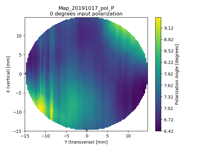
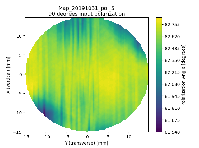
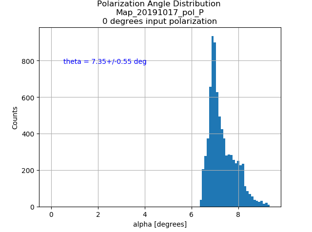
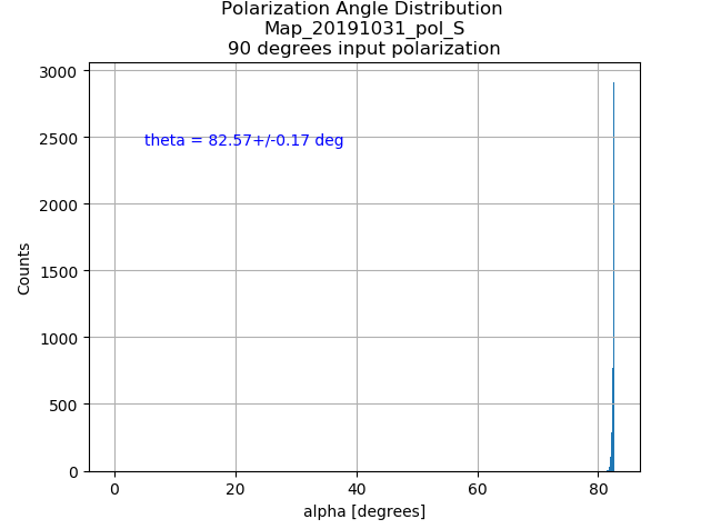
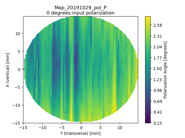
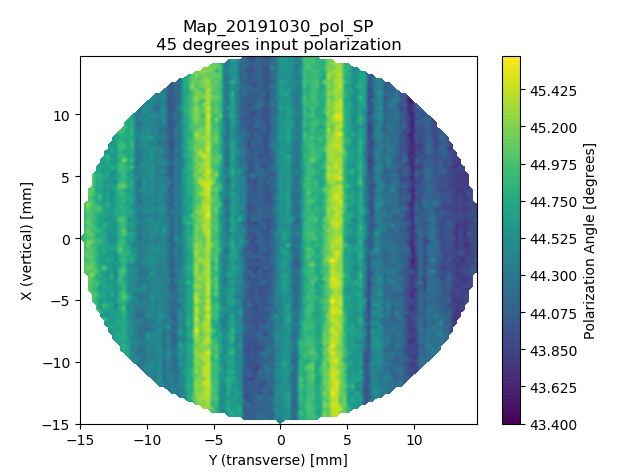
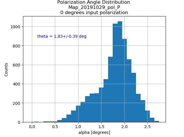
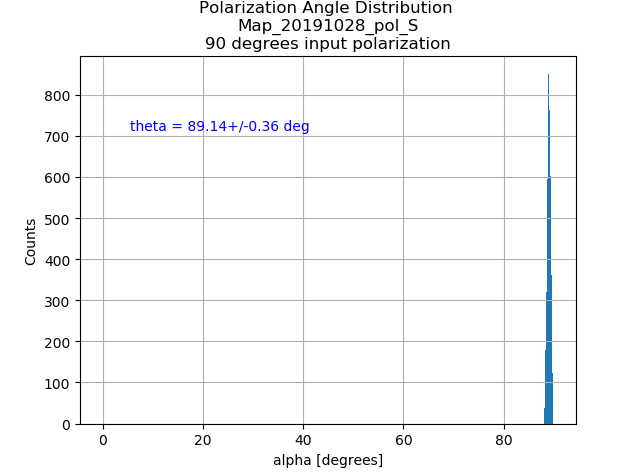
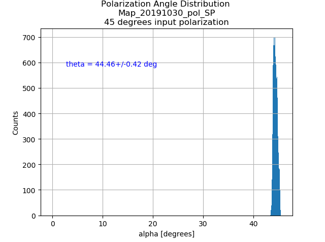
We measured the Polarization map on TAMA#1 with different polarization angles. O degrees represents the pure P- polarization map.
As can be seen, these images show the same pattern in structure. Also the S- and P- polarization both show an apparent offset, which is most likely due to the birefringence effect.
[Aritomi, Matteo, Eleonora, Takahashi]
Yesterday we opened the input chamber with the help of Takahashi-san, and we confirm the intermediate mass was touching and picomotors were at the end range. (See entry #1783)
We adjusted IM mass and moved the picomotors by hand (and josystic) to make the reflection from the input mirror to superpose with the incoming one. It was quite hard to achive the superposition as we didn't notice that the intemediate mass was touching again and the picomotors couldn't move the mirror properly. Also the gatevalve between input and BS distorts the beam and causes multiple reflection.
Pic 1 and 2 show the current position of picomotors. In the pitch case we are quite close to the end of the range.
Today, since the vacuum was restored, we open the gatevalves and we could realign and lock the cavity again.
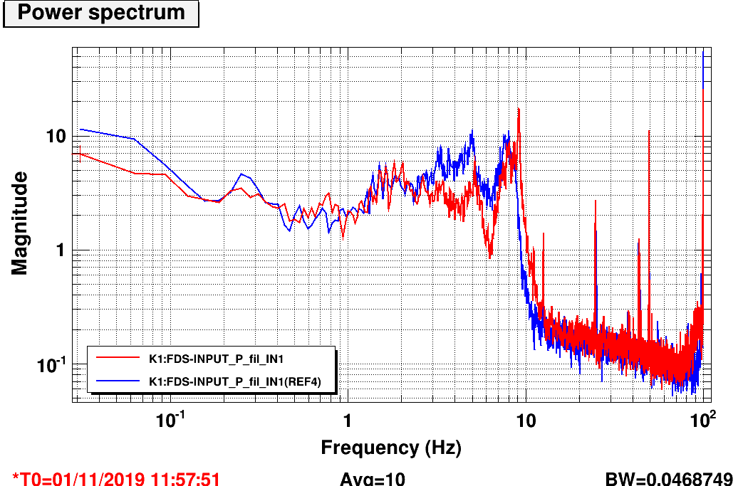
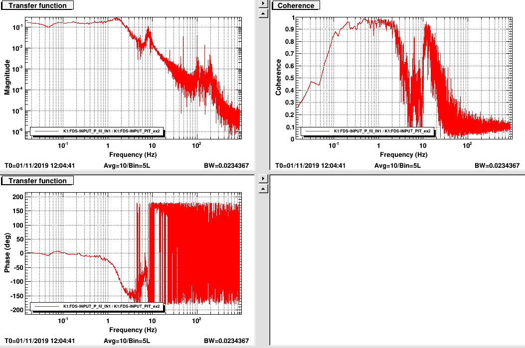
Anyway we found that the spectrum of the pitch motion has a large, sharp peak at 9 Hz that was not there before (pic3) . The TF seems fine (pic4). I wonder if there is still a problem with IM mass. As a first step I will try to adjust the control to damp it better.
Recently we switched off DDS board many times for the sake of avoiding RF signal cross-talk.
But recently every time we switch on again DDS, we heard a strange sound. From the sound, we guess the frequency seems to be a fixed audio frequency.
Up to now, our solution is
1. switch it off the rack containing the DDS board.
2. take out DDS3 board
3. switch on the rack
4. Put back DDS3 board while the power is on
By following this procedure, we could avoid the sound problem. But we still don't know what is the reason for this sound.
[Yao-Chin, Aritomi]
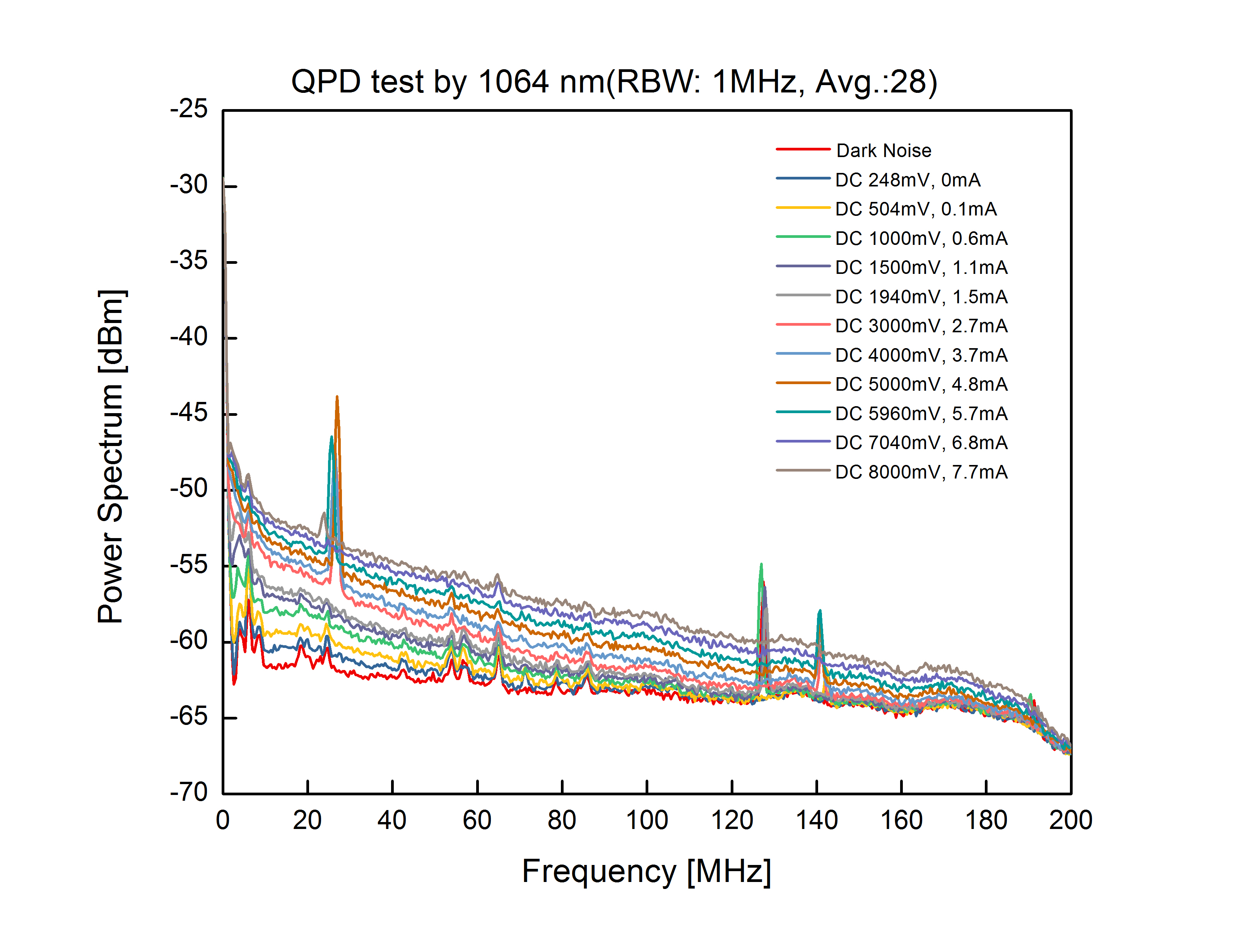
Testing method was same as entry 1785. However, we changed laser source to infrared light of 1064 nm. Infrared light hit in the first quarter of QPD2 (QPD2 input 1). We connected the corresponding DC output to the oscilloscope to check DC voltage. We also connected the corresponding RF output to a 32 dB amplifier and then check its power spectrum by a spectrum analyzer (Keysight N9320B).
We measured the light power, DC voltage, DC current by using "PuTTY", and RF channel power spectrum with RBW of 1MHz and average 28 times shown in pic. 1. Dark noise of pic.1 included the 32 dB amplifier and instrument when no IR light hit to QPD. In this measurement, when light power goes up, power loss is going down unlike the measurement in entry 1785. Green power in entry 1785 was too much since maximum DC current is 10mA according to specification and calculated DC current is already more than 10mA with 53.5 mW of green.
Pic. 2 shows same measurement in NIKHEF. The result is similar to our result, but we have some peaks around 25MHz, 125MHz, 140MHz.
|
Light Power [mW] |
DC Voltage [mV] |
DC Current [mA] |
calculated DC current (mA) (photosensitivity is 0.55A/W according to specification) |
power loss (%) (ratio of measured DC current/calculated DC current) |
| 0.58 | 248 | 0 | 0.319 | 100 |
| 1.25 | 504 | 0.1 | 0.688 | 85 |
| 2.5 | 1000 | 0.6 | 1.38 | 57 |
| 3.7 | 1500 | 1.1 | 2.04 | 46 |
| 4.5 | 1940 | 1.5 | 2.48 | 40 |
| 7.3 | 3000 | 2.7 | 4.02 | 33 |
| 9.5 | 4000 | 3.7 | 5.23 | 29 |
| 11.7 | 5000 | 4.8 | 6.44 | 25 |
| 13.5 | 5960 | 5.7 | 7.43 | 23 |
| 15.5 | 7040 | 6.8 | 8.53 | 20 |
| 17 | 8000 | 7.7 | 9.35 | 18 |

Today we reconfigured the setup to birefringence measurement. First, we measured the reflectance and transmittance under different conditions.
With the P-pol input polarization, we got
P_in = 7.64 mW, P_refl = 7.559 mW, P_trans = 0.206 mW
R = 0.9894, T = 0.0270
With the S-pol input polarization, we got
P_in = 7.649 mW, P_refl = 7.602 mW, P_trans = 0.007 mW
R = 0.9939, T = 0.0009
Then, we did the S-polarization map on TAMA#1. The result will be shown tomorrow.
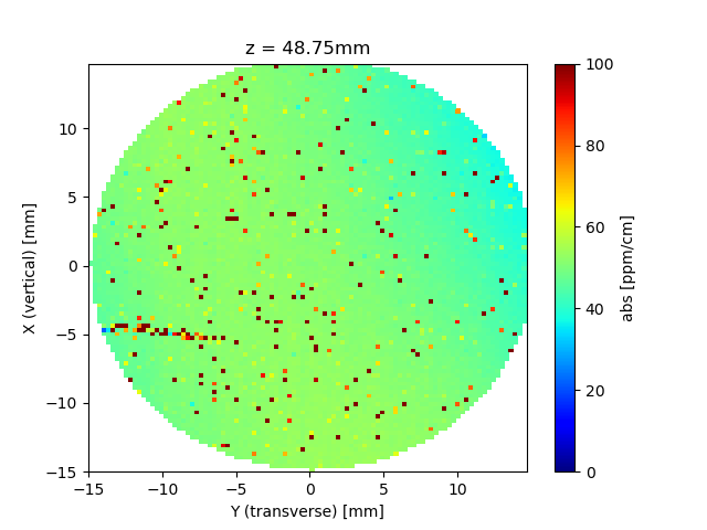
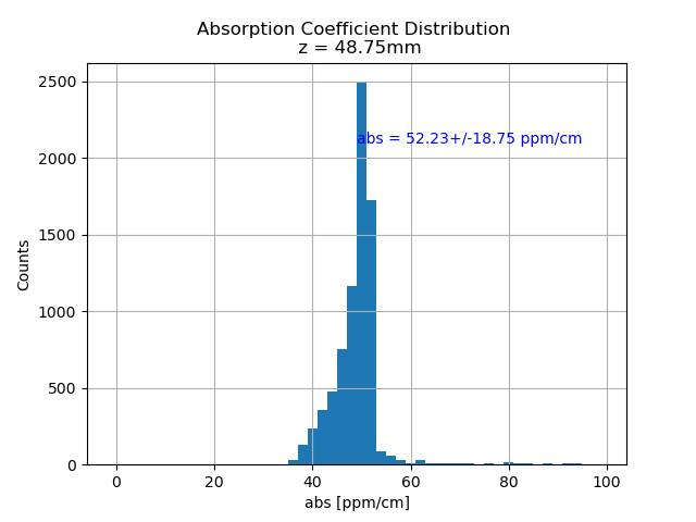
We reconfigured the PCI system and measured the absorption map of the OSTM sample with ATC coating.
As can be seen, the figure shows a large value of absorption. And there are many spots with absorption excesses. Most likely, they are due to defects of the coating
[Yao-Chin, Yuhang]
Frequency from DDS with -6.5dBm sent to input LO & RF ports of demodulator (ZFMIQ-70D). The demodulator output I & Q ports connected low pass filter of DC-2.5MHz. We measured the Vpp and phase difference of I & Q ports from oscilloscope.
Note: Unbalance Amplitude (dB)= 20* log (Vpp of I port/ Vpp of Q port)
(I) Fixed LO port frequency of 78 MHz
(II) Fixed difference frequency of 100 Hz between LO and RF ports tune range from 66 to 80 MHz.
|
LO
(MHz)
|
RF
(MHz)
|
Vpp of I
(mV)
|
Vpp of Q
(mV)
|
Unbalance Amplitude
(dB)
|
Phase Difference btw I&Q
(degree)
|
|
66.0001
|
66
|
260
|
260
|
0
|
91.2
|
|
67.0001
|
67
|
262
|
260
|
0.07
|
90.1
|
|
68.0001
|
68
|
266
|
260
|
0.20
|
90.9
|
|
69.0001
|
69
|
266
|
260
|
0.20
|
90.6
|
|
70.0001
|
70
|
270
|
260
|
0.33
|
90.7
|
|
71.0001
|
71
|
272
|
260
|
0.39
|
90.9
|
|
72.0001
|
72
|
274
|
260
|
0.46
|
90.9
|
|
73.0001
|
73
|
276
|
259
|
0.55
|
90.6
|
|
74.0001
|
74
|
278
|
258
|
0.65
|
89.8
|
|
75.0001
|
75
|
281
|
258
|
0.74
|
90.2
|
|
76.0001
|
76
|
282
|
258
|
0.77
|
90.2
|
|
77.0001
|
77
|
282
|
255
|
0.87
|
90.6
|
|
78.0001
|
78
|
286
|
254
|
1.03
|
90.4
|
|
79.0001
|
79
|
286
|
254
|
1.03
|
90.1
|
|
80.0001
|
80
|
286
|
251
|
1.13
|
90.9
|
* Phase: Q=I+90o for LO>RF, Q=I-90o for LO<RF
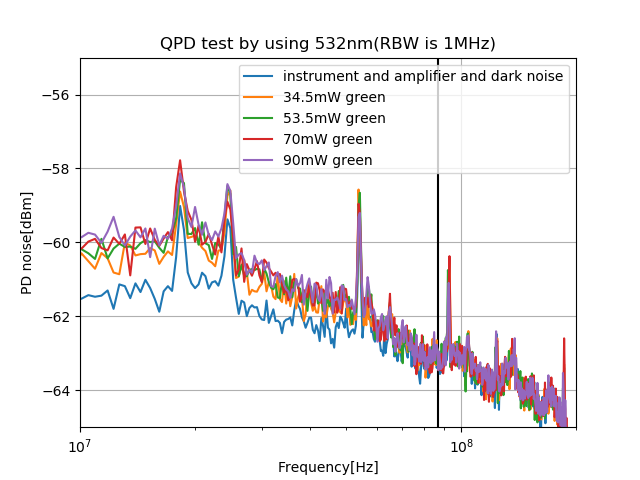
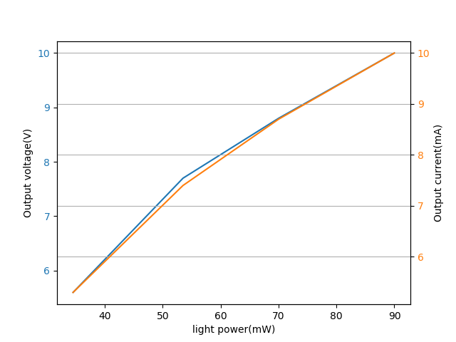
To have an idea about how PD responses (at RF frequency) to green light. We did this test.
The test set-up is as shown in the attached figure 1 and 2. We put a periscope after the first green FI. It brings the green beam up to the second layer of the bench. At the second layer, we put a lens and a steering mirror to make sure the light is small enough and hit in the first quarter of QPD2. We connected the corresponding DC channel to the oscilloscope to check the output voltage DC. We also connect the corresponding RF channel to a 32dB amplifier and then a spectrum analyzer(Keysight N9320B) to check its noise spectrum.
To avoid any modulation and even RF cross-talk, we turned off the DDS system. The green power is changed by moving the offset of high voltage driver(connect to the PZT of SHG). We checked this offset is stable enough so that the green power doesn't change larger than 4% within the time of one measurement.
Within one measurement, we measured the light power/output voltage DC/output current(measured by using the 'putty')/RF channel spectrum.
| Output voltage DC(V) | Light power(mW) | Output current(mA) |
Calculated current(mA) (photosensitivity is 0.2A/W according to specification) |
power loss (%) (inferred from measured and calculated current) |
|---|---|---|---|---|
| 5.6 | 34.5 | 5.3 | 6.9 | 23.2 |
| 7.7 | 53.5 | 7.4 | 10.7 | 30.8 |
| 8.8 | 70 | 8.7 | 14 | 37.9 |
| 10 | 90 | 10 | 18 | 44 |
The relation between power and voltage/current is attached in figure 4.
I also calculated the shot noise by using this formula: shot noise = 10*log((sqrt(2*1.6e-19*I)*sqrt(RBW))**2*35/1mW)+32+22, then I got the calculated shot noise level
| Output Voltage DC(V) | Calculated shot noise(dBm) |
|---|---|
| 5.6 | -48.3 |
| 7.7 | -46.8 |
| 8.8 | -46.1 |
| 10 | -45.5 |
While the measured shot noise is attached in figure 3, which shows -60dBm for all different light power.
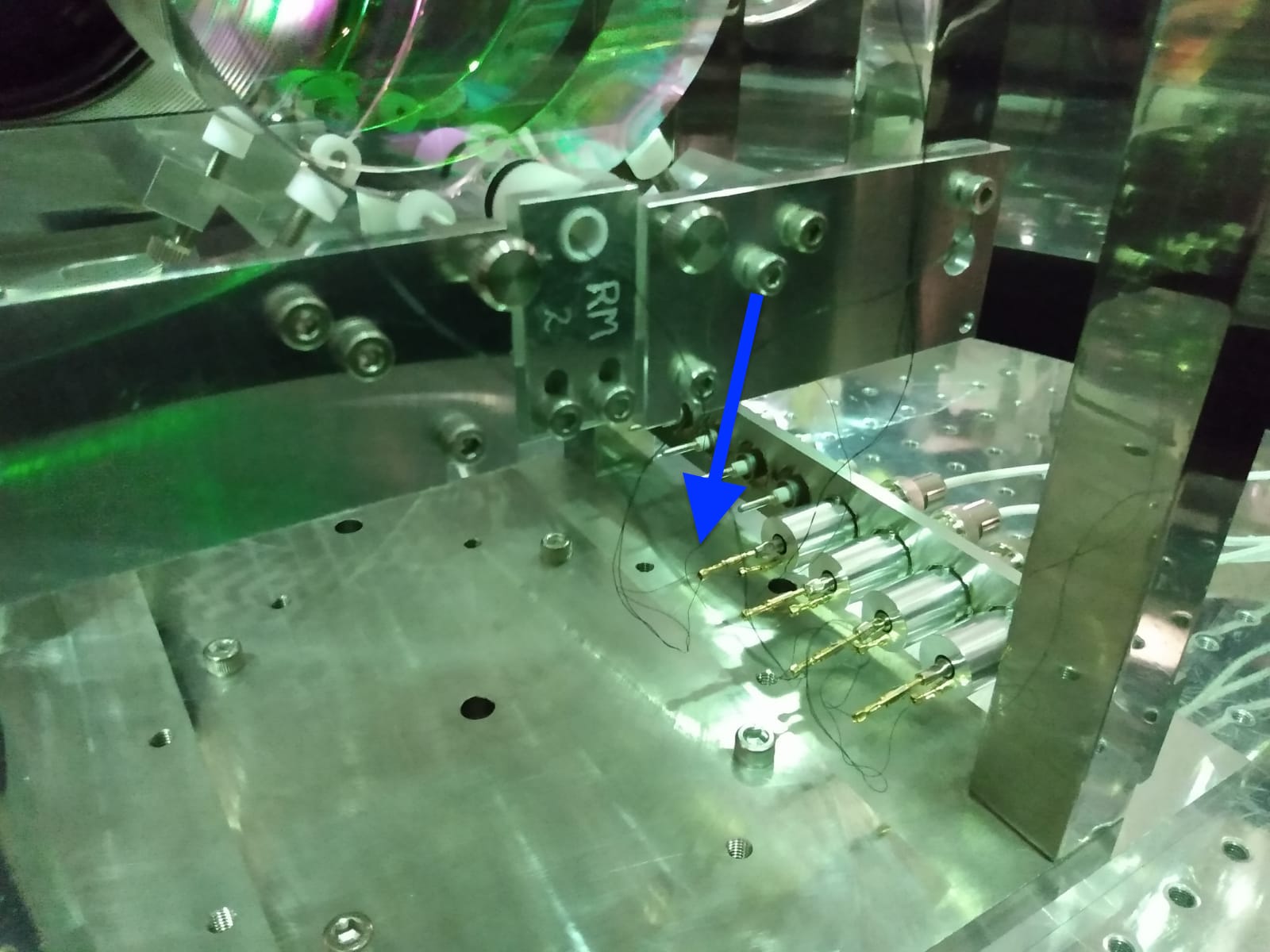
On Tue 29/11 we open INPUT vacuum chamber. Takahashi-san found the wire to the ground pin of the circuit of the top coil was broken. See picture.
He repaired it. We closed the chamber and check the the coil is working fine now.
[Yuhang, Aritomi]
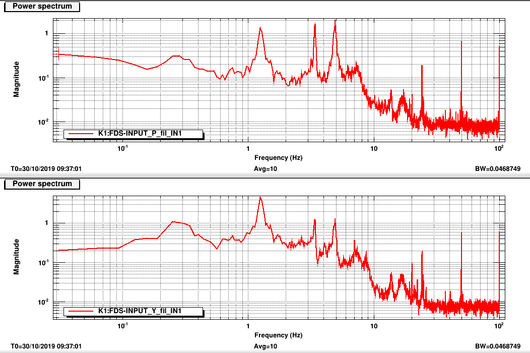
We had homodyne noise spectrum bump problem reported in entry1529.
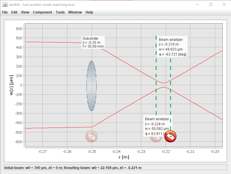
One of the reasons could be the cut issue of PD, and I checked the entry1159. I found that the 'beam analyzer' was put in a wrong position. The corrected version is attached here. In this version, the 'beam analyzer' is marking the position where the beam size(100um) is 5times smaller than the size of PD(500um). So we can decide that the homodyne PD should be 26mm~32mm after 30mm lens. This means we have only 6mm range to make sure the beam is smaller enough than the size of PD(500um).
We also measured again the shot noise after this work(attached picture 2 and 3). The bump issue sometimes is till present, but it covers region smaller than 20Hz and rarely show up. But we found small 45Hz and 54Hz peaks which are not present in previous measurement. They may due to we didn't cover bench as before(now the west side is half open and south side is open).
Today we had another failure of the BS TMP.
The error is number 089 which is for "Rotor vibration". The pump stopped autonomously.
After consulting with Takahashi-san we closed the gate valve between the TMP and the BS chamber as well as the valve between the BS TMP and RP and switched off the BS RP.
At this stage the pressure in the BS+PR was around 10^-3 mbar. In the input tower it was 10^-7 and in the arm 10^-8 (the gate valve around the input tower were still closed due to the work performed yesterday on the input mirror coil).
We open the gate valve between input and PB+PR and the pressure stabilized around 10^-4. So we let it go down few minutes until the pressure in input+BS+PR reached 10^-6 and then we opened the gate valve between the arm and the CITF. After that the pressure stabilized around 10^-6 and it is slowly going down.
In this moment there is only the pumping system of the input tower working for the central area.
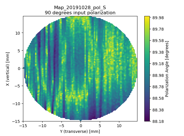
This entry is log on 28th Oct.
I cut some teflon sheet for cushioning between glass window and adapter.
We measured the polarization map of OSTM with different polarization angles.
0 degrees represent pure p-polarization. 90 degrees represent pure s-polarization. 40.5 degrees represent a mixture of sp polarization with a ratio of 1 to 1.
[Matteo, Eleonora]
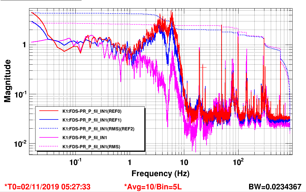
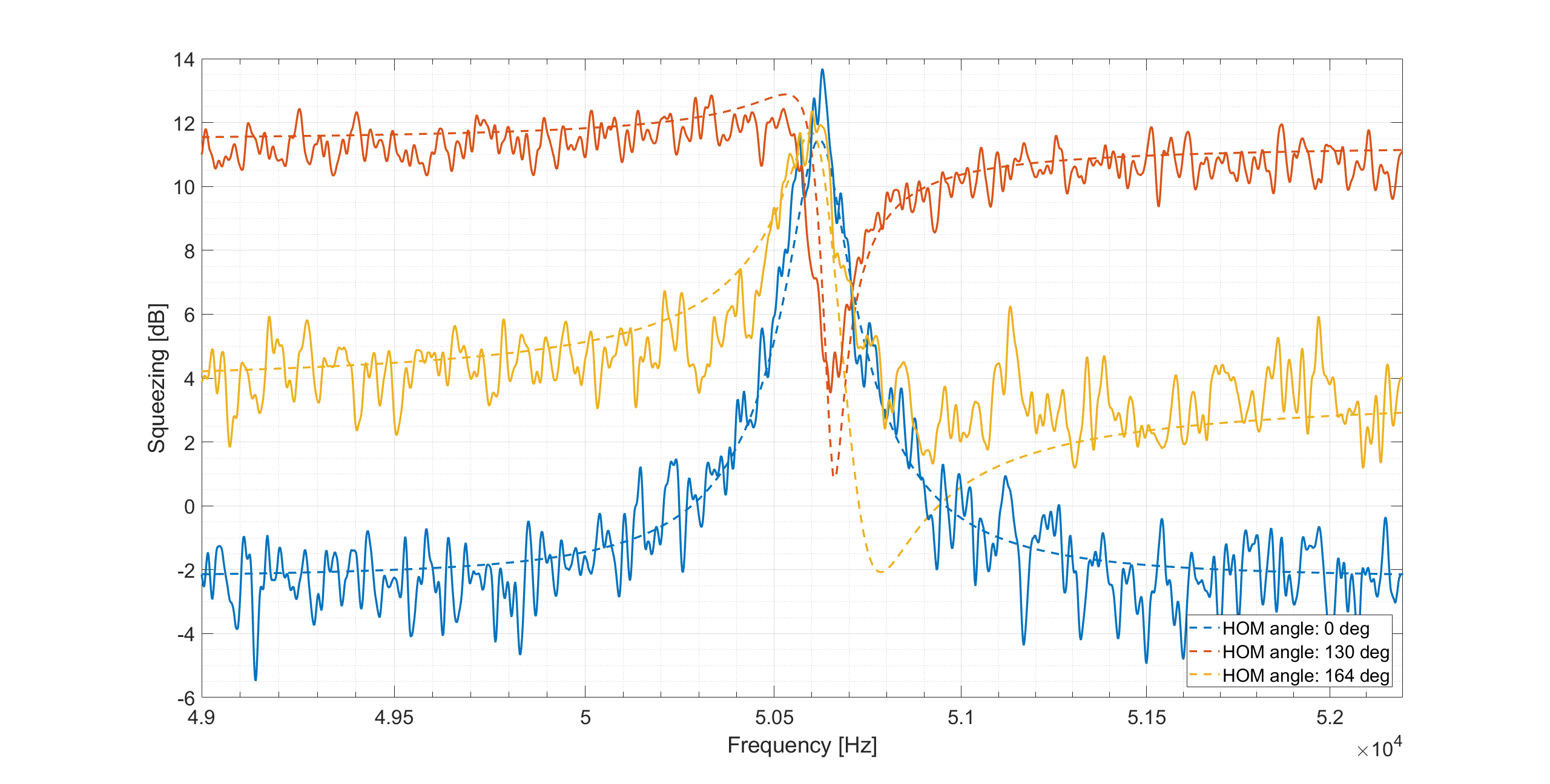
We used the code that simulates the homodyne spectrum for FDS at differente angles (entry #1774) and tried to optimize the angle to fit the data of our last FDS measurement (entry #1751)
The results in the attached figure show a quite good agreement between data (solid line) and simulation (dotted line)
The degradation parameters used in the code are the following:
sqz_dB = 16; % produced SQZ
L_rt = 100e-6; % FC losses
L_inj = 0.33; % Injection losses
L_ro = 0.11; % Readout losses
A0 = 0.1; % Squeezed field/filter cavity mode mismatch losses
C0 = 0.05; % Squeezed field/local oscillator mode mismatch losses
ERR_L = 5e-12; % Lock accuracy [m]
ERR_csi = 80e-3; % Phase noise[rad]
det = 50.62e3; % detuning frequency
int = 2e3; % frequency range = det+/-int
t_in_q = 0.0014; % input mirror transmission
gamma_fc = ((t_in_q + L_rt)/2)*fsr; % = 59.6*2*pi
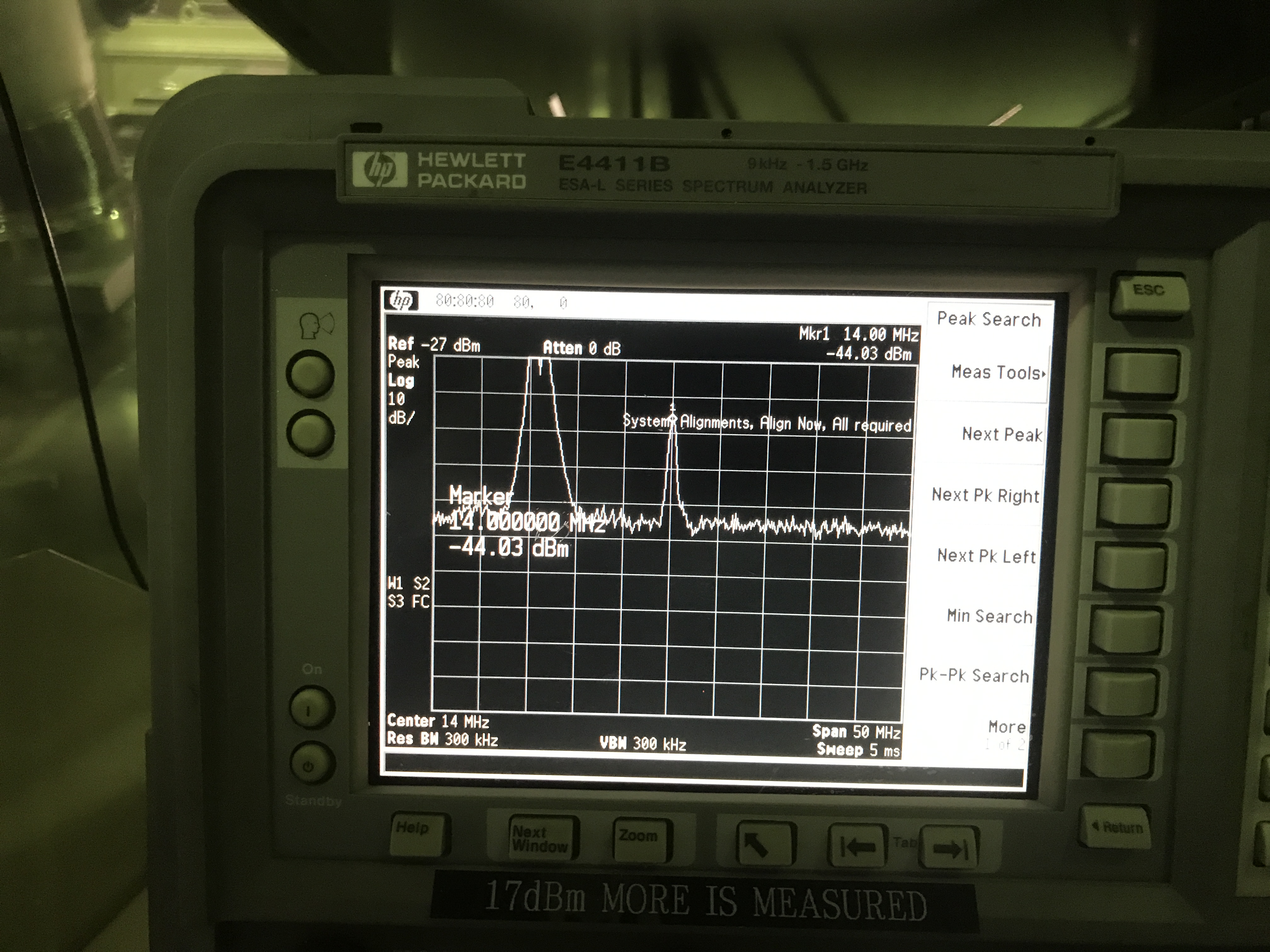
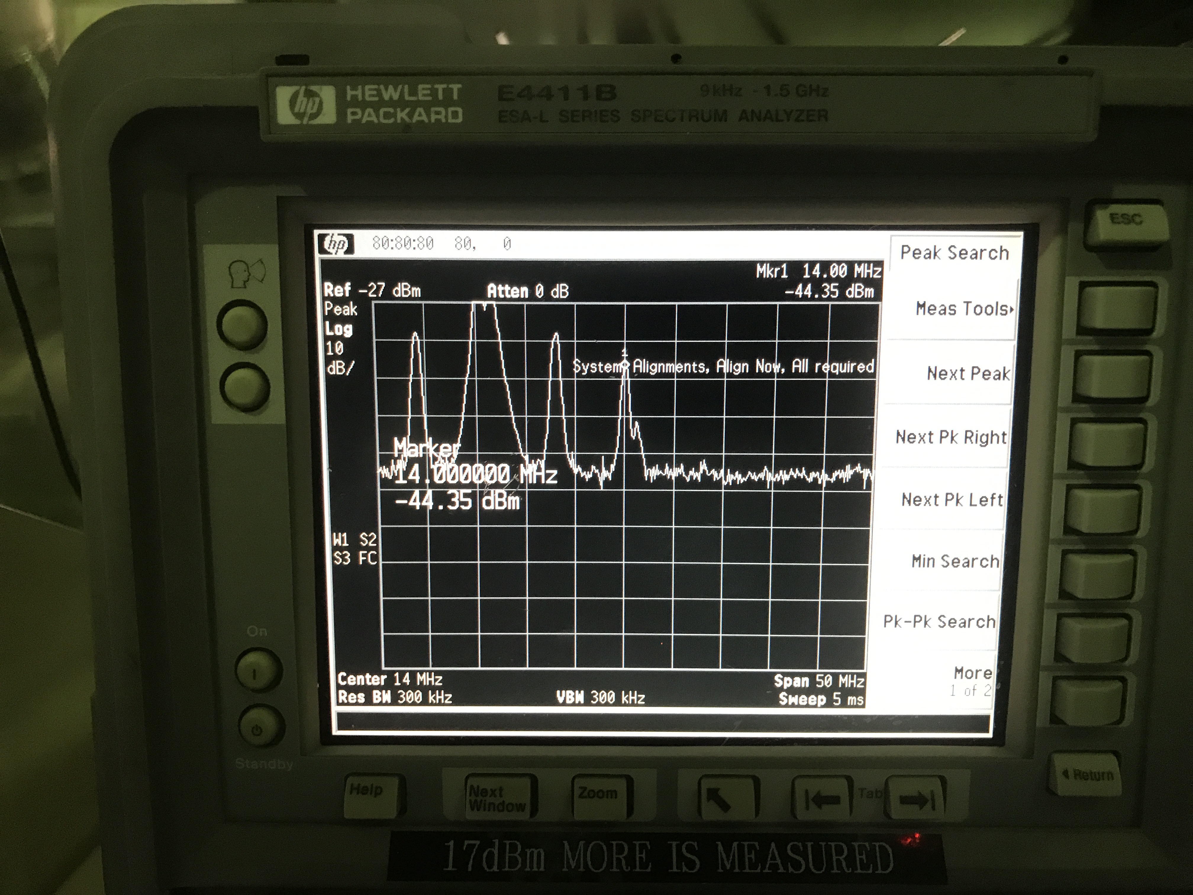
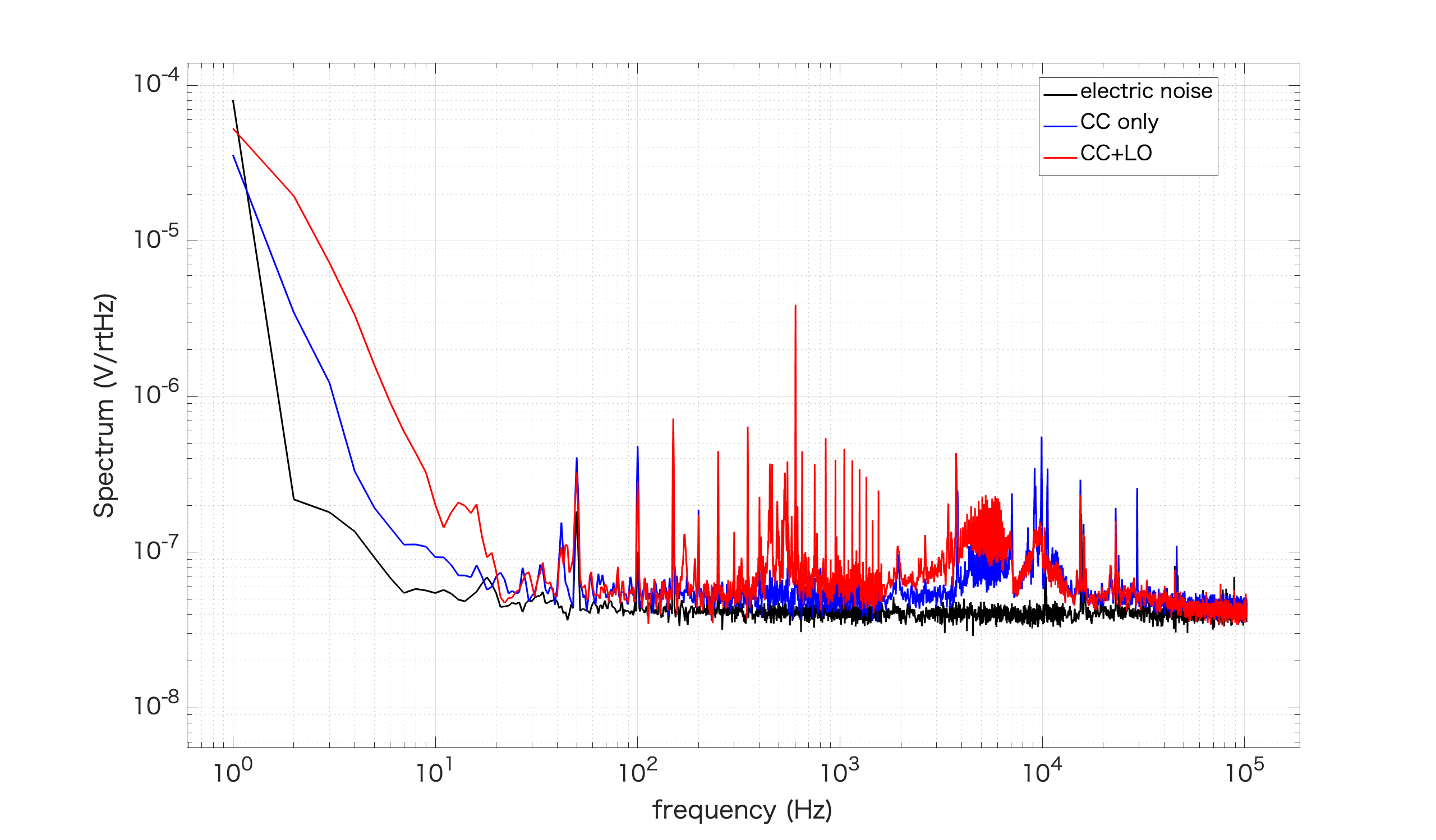
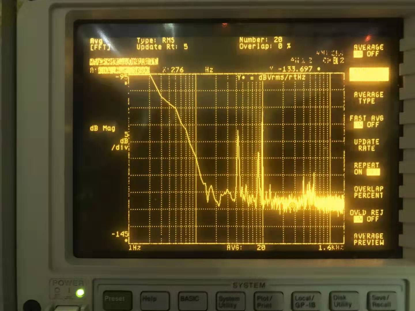
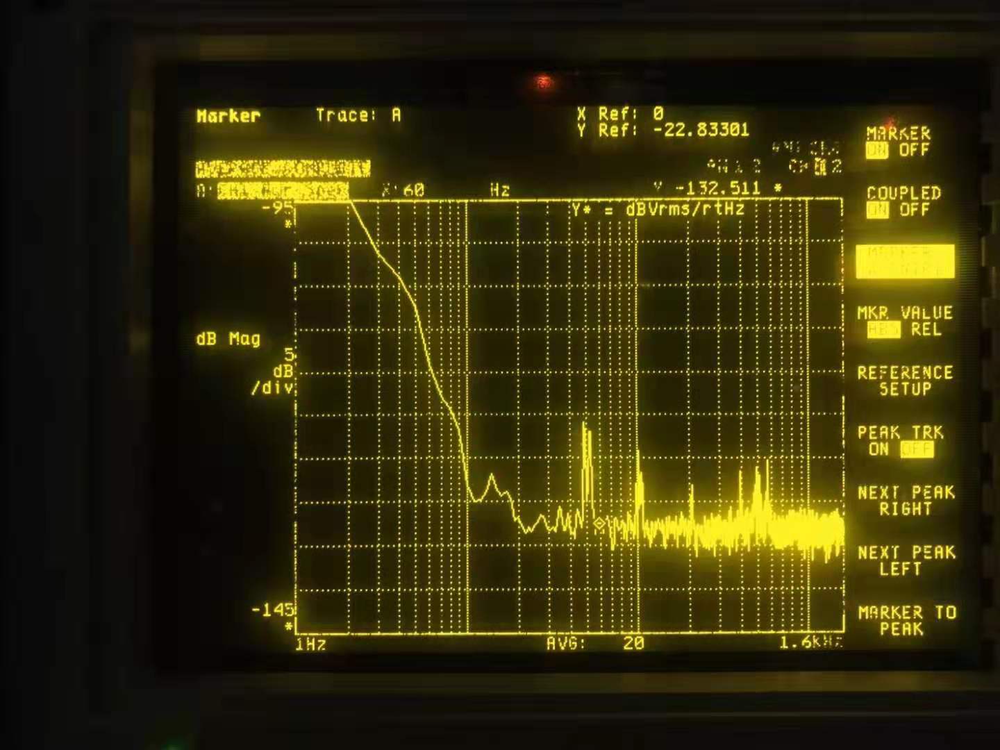
To check how much second harmonic of 7MHz CC/LO beat note affects 14MHz CCSB beat note, I put TAMA RFPD before AMC and detected LO and CC at the same time. CC is directly injected from OPO and CC1 is locked. I compared 14MHz peak height with only CC or CC+LO. Pic. 1,2 shows 14MHz signal with only CC or CC+LO. Apparently 14MHz peak height is almost same.
Then I demodulated the 14MHz signal with 14MHz and measured spectrum of the demodulated signal (Pic. 3). Spectrum with CC+LO has some excess noise compared with only CC and the noise shape seems similar to CC2 phase noise. This noise should come from second harmonic of 7MHz.